Beyerdynamic MCW-D 200 Configuration guide

FEATURES
• Central control unit to control up to 65000 digital wireless
microphone units
• Specific DSSS modulation (Direct Sequence Spread
Spectrum) ensures a high noise immunity when used with other
wireless systems in the 2.4 GHz frequency band
• Wireless transmission in the world-wide approved
frequency range of 2.4 GHz
• Digitally encoded audio signals prevent unauthorised listening
• Up to 15 channels for audio transmission (full duplex)
• Four default slots for four microphone units
(e.g. 3 delegates and 1 chairman)
• Integrated antenna splitter/combiner for diversity reception
• Digital limiter function per input channel (can be configured)
• Manual or Request-to-Talk mode
• RS 232 interface for external operation with PC
or media control
• IPX network connection for external operation via PC or media
control system, especially when a media control system is
connected to the RS 232 interface
• MCW-D 200 Editor software for Windows®to configure the
control unit and microphone units
• Available as an option: MCW-D 200 Controller software for
Windows®to control the discussion system
• Available as an option: MCW-D 200 Voting software for
Windows®for votings during or after the discussion
• Remote RF-receiving and transmitting antennae for large distances
• Quick setup for discussions without additional sound
contracting devices
• Due to RF operation no extensive installations for transmitter or
receiver components necessary (compared to infrared technology)
• Additional audio input for e.g. wireless microphones
• Recording output for documentation
• Master output for external sound contracting systems
• All connections are plug-in type
• 19" desktop housing, 2 HU
• Options:
CA 2450
P-C board for 1 transmitting and 1 receiving channel,
2.4 GHz - DSSS (Direct Sequence Spread Spectrum)
3 modules can be used at maximum
CA 2451
P-C board Individual In/Out, in conjunction with the
MCW-D 200 Editor software the zoning mode is enabled which
allocates audio signals individually.
For multi-channel applications, e.g. interpreting applications, the
CA 2451 is needed.
CA 2452
P-C board Digital In/Out, with AES/EBU (XLR) and S/PDIF (RCA)
connections
beyerdynamic GmbH & Co. KG
Theresienstr. 8 | 74072 Heilbronn – Germany
Tel. +49 (0) 71 31 / 617 - 0 | Fax +49 (0) 71 31 / 617 - 224
For further distributors worldwide, please go to www.beyerdynamic.com
Non-contractual illustrations. Contents subject to change without notice. E3 / MCW-D 200 (02.10)
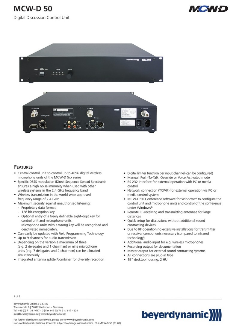
MCW-D 200
Digital Discussion Control Unit
Order # 472.522
1 of 3

DESCRIPTION
Digital control unit for an unlimited number of wireless microphone
units with or without loudspeaker and for multi-channel
transmission. Integrated diversity combiner for max. 8 smart link
receiving modules. As a standard max. 4 microphone units can
be switched on (e.g. 3 delegates and 1 chairman) and 5 audio
channels can be transmitted to the microphone units. With
additional printed circuit boards up to 7 microphone units can be
switched on and 8 audio channels can be transmitted to the
microphone units.
There is a constant status inquiry, monitoring or control due to the
bi-directional data connection to the microphone units. Individual
microphone units can be activated via the RS 232 serial interface.
The complete discussion system can be switched off via a control
command or by pressing the “Stand-by” button on the front. The
8 LEDs on the front indicate the assigned transmission channels of
the microphones. To increase the security of the system, the control
unit can operate in the “security mode” i.e. the control unit only
operates with microphone units which have the same PIN code. As
an option the control unit can be complemented with the
“Individual In/Out” and “Digital In/Out” board. With the
“Individual In/Out” board it is possible to transmit and receive the
signals of the individual activated microphone units or to transmit
up to 8 audio signals to the microphone units. With the “Digital
In/Out” board the audio signals can be transmitted as AES/EBU or
S-PDIF standard.
SUPPLIED ACCESSORIES
Power cable
MCW-D 200 Editor
Configuration software . . . . . Order # 473.685
OPTIONAL ACCESSORIES
CA 2411 Angled rod antenna, 2.4 GHz . Order # 464.236
CA 2412 Rod antenna, 2.4 GHz . . . . . . Order # 464.244
CA 2413 Planar antenna, 2.4 GHz . . . . Order # 464.252
CA 2420 Standard cable, 2.4 GHz,
sale per metre . . . . . . . . . . . . Order # 464.260
CA 2421 Standard cable, 2.4 GHz,
N(HF)-N(HF), 10 m . . . . . . . . . Order # 464.279
CA 2422 Standard cable, 2.4 GHz,
N(HF)-N(HF), 20 m . . . . . . . . . Order # 464.287
CA 2430 Low attenuation cable,
2.4 GHz, sale per metre . . . . . Order # 464.295
CA 2431 Low attenuation cable,
2.4 GHz, N(HF)-N(HF), 10 m . . Order # 464.309
CA 2432 Low attenuation cable,
2.4 GHz, N(HF)-N(HF), 20 m . . Order # 464.325
CA 2441 RT Antenna amplifier for
transmitting and receiving,
(10 dB gain), remote power
supply 5 V via antenna cable . . Order # 470.309
CA 2441 T Antenna amplifier for
transmitting, (8 dB gain),
remote power supply 5 V
via antenna cable . . . . . . . . . . Order # 470.317
CA 2442 Adapter
N(HF) Female - SMA Male . . . Order # 464.376
CA 2443 Adapter
N(HF) Female - SMA Female . . Order # 464.384
CA 2444 Adapter
N(HF) Male - SMA Female . . . Order # 464.392
CA 2445 Adapter
N(HF) Male - SMA Male . . . . . Order # 465.151
CA 2450 PCB 1 transmitting/
1 receiving channel,
2.4 GHz DSSS . . . . . . . . . . . . Order # 464.899
CA 2451 PCB Individual In/Out . . . . . . . Order # 464.406
CA 2461 19" antenna connection
panel, 3 x N(HF) . . . . . . . . . . . Order # 465.224
CA 2462 3/8" antenna mounting kit . . Order # 465.232
MCW-D 200 Controller
Software to control the
system via PC . . . . . . . . . . . . . Order # 473.677
MCW-D 200 Voting
Software for public or
secret votings. . . . . . . . . . . . . Order # 474.460
beyerdynamic GmbH & Co. KG
Theresienstr. 8 | 74072 Heilbronn – Germany
Tel. +49 (0) 71 31 / 617 - 0 | Fax +49 (0) 71 31 / 617 - 224
For further distributors worldwide, please go to www.beyerdynamic.com
Non-contractual illustrations. Contents subject to change without notice. E3 / MCW-D 200 (02.10)
MCW-D 200
2 of 3

TECHNICAL SPECIFICATIONS
General
Frequency range. . . . . . . . . . . . . . . . 2400 - 2483.5 MHz
(ISM-band)
Modulation . . . . . . . . . . . . . . . . . . . Direct Sequence Spread
Spectrum DSSS, digital
signal processing acc.
to own standard
Max. number of channels. . . . . . . . . 2*8 useable duplex
channels per system
Signal-to-noise ratio . . . . . . . . . . . . . 80 dB typ., (unweighted
signal-to-noise ratio)
Range between microphone units
and control unit . . . . . . . . . . . . . . . . > 100 m at intervisibility
Power supply . . . . . . . . . . . . . . . . . . 110 - 240 VAC 50/60 Hz
Approval . . . . . . . . . . . . . . . . . . . . . world-wide
MCW-D 200 Control Unit
Frequency response . . . . . . . . . . . . . 70 Hz - 10 kHz (-3 dB)
Operation mode. . . . . . . . . . . . . . . . Diversity (receiver),
separate for each channel
Antenna connection. . . . . . . . . . . . . 3 N-connectors (female)
Remote supply voltage for
antenna amplifier . . . . . . . . . . . . . . . 5 V, max. 2 A
Transmitting power. . . . . . . . . . . . . . . 10 mW per channel (10 dBm)
Connections
Serial control port. . . . . . . . . . . . . . . RS 232, standard with
115 kbps, 8N1
Ethernet port . . . . . . . . . . . . . . . . . . IPX
Master output balanced . . . . . . . . . . XLR, +6 dBu
Master output unbalanced . . . . . . . . RCA, level adjustable
(1.55 V - 300 mV range)
Input balanced . . . . . . . . . . . . . . . . . XLR, +6 dBu
Input unbalanced . . . . . . . . . . . . . . . RCA, level adjustable
(min. 500 mV at max. level)
Integrated limiter to avoid clipping of the input signals
Number of the channels . . . . . . . . . . max. 7 channels can be
used for microphone units
Extensions . . . . . . . . . . . . . . . . . . . . CA 2450, PCB for
additional transmitting/
receiving channel
CA 2451, balanced inputs
and outputs (each
+6dBu nominal level)
with 25-pin Sub-plug
(female)
corresponding to standard
«TASCAM DA Multitrack- . .
Recorder»
Power supply . . . . . . . . . . . . . . . . . . 110 - 240 V AC 50/60 Hz
Fuse . . . . . . . . . . . . . . . . . . . . . . . . . 3.15 A slow-blow
Power consumption . . . . . . . . . . . . . 23 W
Temperature range . . . . . . . . . . . . . . +10° - 50°C
(at < 90% humidity)
Indication . . . . . . . . . . . . . . . . . . . . . 8 channel LEDs (red/green)
and Power LED (red/green)
Depth of rack . . . . . . . . . . . . . . . . . . 380 mm at least
Dimensions (W x H x D) . . . . . . . . . . 19", 2HU
(440 x 88 x 310 mm)
ARCHITECT’SSPECIFICATIONS
Central control unit of a wireless digital discussion system. Specific
DSSS modulation (Direct Sequence Spread Spectrum) ensures a high
noise immunity in the 2.4 GHz frequency band world-wide
approved. An unlimited number of microphone units can be
controlled. 16 bi-directional data channels allow the use of max. 7
audio-voice channels and 8 audio-aural channels (with CA 2450).
As a standard 4 microphone units can be switched on simultaneously.
Automatic frequency allocation. The microphone units can be
extended with additional PCB’s. Diversity technology ensures a high
transmission safety. Operation modes: manual: each participant can
switch his microphone on or off; request-to-talk: the microphone is
released via an operator at a PC, media control system or a micro-
phone unit with function button; voice-controlled allocation: as
soon as someone speaks into the microphone it is switched on;
override: when a microphone is activated, the first one will be
switched off. The complete system can be switched off with the
stand-by button on the front or via a control command of the
serial interface or the IPX network connection. RS 232 serial inter-
face for system configuration, PC or media control system. Audio
input for external signals. PCB available for individual audio output
per voice channel and audio input per aural channel; AES/EBU
digital input and output; S/PDF input and output. All connections on
the rear are plug-in types: audio master output (3-pin XLR,
balanced, RCA, unbalanced), audio input (3-pin XLR balanced, RCA,
unbalanced), antenna input A/B and antenna output (N-RF), as an
option with individual input and output (25-pin Sub-D), Tascam
standard), AES/EBU Digital input and output (3-pin XLR balanced),
S/PDF Digital input and output (RCA unbalanced). 19" desktop
housing, 2 HU, ventilation louvres on top and on bottom.
Dimensions (WxHxD) 440x88x310mm.
Manufacturer: beyerdynamic
Product: MCW-D 200
beyerdynamic GmbH & Co. KG
Theresienstr. 8 | 74072 Heilbronn – Germany
Tel. +49 (0) 71 31 / 617 - 0 | Fax +49 (0) 71 31 / 617 - 224
For further distributors worldwide, please go to www.beyerdynamic.com
Non-contractual illustrations. Contents subject to change without notice. E3 / MCW-D 200 (02.10)
MCW-D 200
3 of 3
Other manuals for MCW-D 200
2
Other Beyerdynamic Control Unit manuals
Popular Control Unit manuals by other brands
Radionics
Radionics D8128D installation instructions
VIA Technologies
VIA Technologies QSM-8Q60 user manual
LIFE home integration
LIFE home integration ACER RG1R UNI DL Instructions and warnings for installation, use and maintenance
Faderfox
Faderfox NEW MODULE PC12 user manual
Reer
Reer Aus X Series Use and maintenance

Hitachi
Hitachi IR.LINK user manual
U-Line
U-Line H-3449 manual
WEG
WEG SSW07 Series installation guide
YASKAWA
YASKAWA VIPA SPEED7 Operation manual
HESCH
HESCH HE 5760 operating instructions
GEM
GEM N086 Installation, Operating and Maintenance Instructions for the Installer and the User
Pepperl+Fuchs
Pepperl+Fuchs VAA-2E-G4-SN instruction manual
