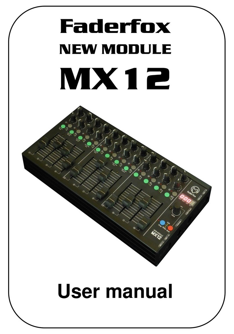
Faderfox NEW MODULE PC12 User manual

Faderfox
NEW MODULE
PC12
User manual

Provision of guarantee and product liability
The seller warrants for faultless material and proper manufacture for a period of 24 months from the date of sale
to the end user.
Excluded from the stated guarantee are defects on parts as the result of normal wear-and-tear. These parts are
mostly faders (sliding guides), potentiometers, encoders, buttons, switches and touchpads.
Also excluded from the guarantee are damages that are the result of :
incorrect or inappropriate handling, excessive force, mechanical or chemical influences, incorrectly connecting
the instrument with other instruments, incorrect or inappropriate use.
The warranty is void if the instrument is opened or changed. In addition, there is no warranty for individual parts
and components (in particular, semiconductors) and disposables/ consumables. The seller is not liable for
consequential damages which are not the result of criminal intent or negligence on his part. The following
conditions must be met in order to claim the warranty services:
- Instrument is either in its original packaging or similar packaging.
- Copy of the invoice with the serial number clearly visible.
- Meaningful error report or description of the error is attached.
The buyer assumes all costs and dangers of return shipments to the manufacturer. Since the user’s manual which
is included with each instrument also affects the warranty conditions (especially regarding safety issues), it is
absolutely essential that you read through and follow all instructions.
Safety precautions and servicing
- Instrument's intended use is based on the functions and procedures contained in this manual
- Read all instructions for use as well as all enclosed literature before using the instrument
- Use only in closed rooms (not for outdoor use)
- Never use in a moist or humid environment (laundry rooms, swimming pools, etc, …)
- Not for use in the vicinity of heat sources (radiators, ovens, etc, …)
- Operational temperature is in the range of 0° - + 40° C
- Not for use in the vicinity of flammable material
- The instrument should not be in direct or prolonged contact with sunlight
- Dusty environmental conditions should be avoided
- Connect only to USB ports of computers or hubs
- No foreign objects are permitted inside the instrument casing
- No liquids should get inside the instrument casing
- Never let the instrument fall to the ground (casing and/or control elements may be damaged)
If the instrument must be opened (for example, to remove foreign objects from the casing or for other repairs),
this may only be done by qualified personnel. The USB-cable must be disconnected before opening the
instrument. Guarantee is void for defects that occur if the instrument was opened by an unauthorised or
unqualified person.
Use a soft towel or brush to clean the instrument. Please do not use any cleaning liquids or water, so you avoid
any damages to the instrument.
Package contents
- Device
- USB cable
- Manual
- Sticker 98 pcs (16 x 9 mm white)

Introduction
Thank you for choosing a Faderfox controller. The PC12 is the second member of a new line called NEW
MODULE. These devices are designed for live use on stage and of course for use in the studio too. All
Faderfox controllers are professionally manufactured in small series in Germany, ensuring high quality.
You can combine two or more NEW MODULE devices to create a large system. The connections are on the
right side to allow a back to back placing of two or more devices. Connect two NEW MODULES by a special
extension port.
Furthermore there are 4 Midi-ports and one USB-port with various routing possibilities.
PC12 as successor of the PC44 is a universal controller for all kinds of Midi controllable hard- and
software.
It is packed in a alu case with the same dimensions like the famous ELEKTRON devices so it’s a great
extension for these devices. But you can use the pot box also with your DAW (recommend as extension for
the MX12) like a classical 12-track-mixer.
The device has 72 standard pots with rubber knobs designed in a 12 x 6 matrix, 12 keys and one
push-encoder. Various kinds of midi commands like control change, note on/off, pitchbend, aftertouch and
program change are possible. You can program every Midi command for every separate control on the device
very fast and easily. Of course you can assign the pots and keys to any of these commands by learning
incoming Midi commands, which is the same procedure you know from your software / DAW.
.
The pots work with standard resolution of 7 bit to have full compatibility to any software and hardware
instrument, effect and DAW. Use the internal 30 setups to save your individual settings. Backup and restore
of all settings by sysex dump is possible too.
The factory settings are perfect to control music and video software products out of the box if they are
freely assignable. So any additional device programming isn’t necessary for many applications.
A special control surface script for Ableton Live 8/9 with all necessary mappings to control 12 tracks
simultaneously is enclosed in the package.
Check out this amazing power box and you will get a reliable mate...

Features
- Universal controller for all kinds of midi controllable hard- and software
- USB interface with bus powering - class compliant / no driver necessary (consumption 110mA)
- 2 MIDI in and out ports with routing and merge functionality
- Extension port to connect a second NEW MODULE device
-72 pots with rubber knobs and standard midi resolution of 7bit
- 1 push encoders with detents (30 pulses) and 14 bit high resolution mode
- 12 buttons with LED for switchable parameters
- 4-digit-display to show values and programming data
- Data feedback for all controls avoid value jumps
- Programmable value ranges with min/max values
-Fast control assign by incoming midi commands (assign whole rows of controls by one command)
- All controls (incl. push buttons) fully programmable in the device by channel, type, number and mode
- Different command types like control change (CC), pitch bend, aftertouch, program change and notes
- Advanced programming functions like copy, paste, duplicate, channel sets
- 30 setups with backup/restore function contain all controller settings and presets
-Switchable Snap function for all pots to avoid value jumps
- Sanpshot and Preset functions to send momentary values or stored presets for all pots/keys (30 presets)
- Upgradable firmware by simple Sysex-dump
- Very compact andsolid design in a black metal casing (size 340x176 6x 5 mm, weight 1.3 kg)
-Same size as the ELEKTRON devices (ELEKTRON accessories like dust cover and bags fit perfectly)
-Cascading of NEW MODULE devices one behind the other due to the side connections
System requirements
- PC or Mac with a free USB port (1.0 or higher) or any USB hub
- MIDI device with standard MIDI in/out port
- USB power adapter (5V min 200mA) if you want to control midi gear only

Connections
The device has four ports each with one in- and one out-port:
- USB
- MIDI 1
- MIDI 2
- EXTENSION
All controller data will be sent to each of the four available out ports simultaneously. Internal connections
between the ports are possible by the routing functionality (see chapter setup / routing). In the case of a
routing the incoming data will be merged to the controller data of the device. You can route only one in
port to each out port.
If you don’t connect a computer it’s necessary to power the device by any kind of USB power adaptor or
by the extension port thru another NEW MODULE device..
Extension port
The extension port is a 8-pin-interface to connect two NEW MODULE devices.
Please use only a crossover ethernet patchcable for this port and don’t connect to any other devices !
The interface allows to power a second device so you need only one USB connection to a computer or power
adaptor for two devices. Further all controller data will be interchanged between the devices.
There are pins for power, one in-port and one out-port. It’s also possible to route the extension in- and
out-ports to any other port (MIDI, USB).
How to setup
Below you find three examples of possible setups. First setup comes with one or two NEW MODULEs and a
computer with ABLETON LIVE. The other two setups contain one or two NEW MODULE devices and one
or two ELEKTRON devices (RYTM, OCTATRACK, ANALOG FOUR). Note that you set the ELEKTRONs
to different Midi channels so you can control each ELEKTRON by each NEW MODULE. Note the different
internal routings for sync- and all other data.


Controller mode
Controller mode is the basic mode of the PC12. Here the pots, encoder and buttons are used to control any
parameter in your soft- or/and hardware by standard midi commands like CC and notes.
The encoder can send different commands via turn and push. You can see the numerical value in the display
too. A programmed acceleration gives a better feeling for the encoder so you can go from min to max value
easily. Hold down the red shift button while you turn the encoder to have a precise control without
acceleration.
The green buttons can be programmed to various modes like the pots and encoder too. So they can work as
momentary switch or in toggled mode, sending notes, CC, program change or aftertouch commands.
Snap function
The pots can work in snap or jump mode. In snap mode you have to catch the last value which avoids any
possible value jump after feedback data. The last value and two arrows in the display show the necessary pot
movements to catch the value.
Jump mode works like a standard controller so the data will be sent immediately.
Switch between the two modes (snap / jump) by pressing the blue button shortly.
Red LED next to the blue button shows the following:
Off = All controls in jump mode
Lit = All controls in snap mode
Blinking = different modes (snap/jump) are programmed in the setup
Hold down red shift button while you turn a pot to suppress data sending temporarily. This is also useful to
catch the last value exactly.
Special shift functions
You can use the green buttons while holding down the red shift button to get the following special functions:
- button 1 to 10: select setups in the current tenth group
- button 11: activates/deactivates monitor mode
- button 12: sends a snapshot (current values) of all controls
The monitor function shows incoming and outgoing Midi data. Arrows in the display flash bright when the
device transmits or receives controller data. Low flashing indicates midi clock or other midi data. Each
display digit represents a Midi port described below the display. The upper arrows show outgoing data and the
lower arrows flashes for incoming data. Monitor function is great to check routings etc.
A snapshot includes all current pot/encoder values and the values of all buttons with toggle mode.
Presets
There is also a new preset functionality which allows to store and send values of all controls. That’s great for
initialization. You can store a total of 30 presets in the device. The tenth group (buttons 1 to 10) follows the
setup number. (for instance the setup 15 is currnetly selected so you can send/store presets 11 to 20 by the
buttons 1 to 10).
Store current values of all controls to a preset by the following steps:
- hold red shift button and press green button 12 to send a snapshot
- hold blue button and press any green button 1 to 10 until all green leds flash shortly
To send a preset hold the blue button and press any green button 1 to 10 shortly.
Presets include only the control values and not the commands itself. That means you can use different presets
for each setup or one preset for different setups.

Edit mode
The edit mode allows the programming of the controls (pots, encoder and buttons). Start and leave edit
mode by holding down shift key and press the blue key. The activated edit mode is indicated by blinking
yellow Edit-LED. All data will be stored in the currently selected setup automatically by leaving the edit
mode.
To edit any control you have to choose the control number first. There are two ways to do so:
1. press button 1 (the left green button) and then select the control by the encoder or
2. holding down the blue button while you move the wanted control
Then you can set different properties by selecting them with button 2 to 8 (see below) and changing with
the encoder.
To copy properties separately to all controls of same row (pots or buttons), hold down the button 2, 3, 4, 5,
7 or 8 while running bar lines shown. This makes editing much faster if you want to have same functions
on all controls in same row.
Hold down the red shift key and turn the encoder to send Midi commands in edit mode. Pots always send
Midi commands in edit mode.
----
4 lines in the display means that the property isn’t available
Control number (Button 1)
P01
...
12A
…
F
select pot 1 to 12 in rows A to F for editing
Enc
select encoder for editing
Pbt
select encoder push button for editing
b01
....
08
select green button 1 to 8 for editing
You can see the control and row numbers on the faceplate.
Display scale (Button 2)
Pot / encoder scales:
OFF
no display control
Std
standard display-control (0 to 127) by the device and by external command
bPoL
bipolar display-control (-63 to 63) by the device and by external command
(for high resolution mode running bar lines per step on right display)
Button scales:
OFF
no LED control
Std
standard LED control by the device and by external command
EHt
LED control only by external commands
External control by feedback data with same commands as corresponding buttons.

Command type (Button 3)
Pot types:
notE
note command (note on for right side, note off for left side)
CC
control change command in 7 bit absolute mode (values 0 to 127) most used standard-mode
Pr
g
C
program change command (values 0 to 127)
Pbnd
pitch bend command 14 bit (values 0 to 16383) Resolution 7 bit !
AFtt
aftertouch (channel pressure) command 7 bit (values 0 to 127)
Encoder types:
CCr1
control change command in relative mode 1 (values 1/127)
CCr2
control change command in relative mode 2 (values 63/65)
CCAb
control change command in 7 bit absolute mode (values 0 to 127) mostly used as standard
Pr
g
C
program change command (values 0 to 127)
CCAh
two control change commands (MSB/LSB) in 14 bit highres mode (values 0 to 16383)
Pbnd
pitch bend command 14 bit (values 0 to 16383)
AFtt
aftertouch (channel pressure) command 7 bit (values 0 to 127)
notE
note command (note on for turning clockwise, note off for turning counter clockwise)
Button types:
notE
note command
CC
control change command
Pr
g
C
program change command
AFtt
aftertouch (channel pressure) command
(for all button types: upper value = press/on, lower value = release/off)
Command mode (Button 4)
Pot modes:
JUMP
jump mode, command will be sent immediately by moving the control
SnAP
snap mode, sends command not before catching the last value by moving the control
Encoder modes:
Acc0
no acceleration by faster turning
Acc1
low acceleration by faster turning
Acc2
middle acceleration by faster turning
Acc3
max acceleration by faster turning
Button modes:
btn
send momentary command (upper value = press, lower value = release)
togL
send toggle command (upper value = on, lower value = off)

Command channel (Button 5)
Ch01
....
16
choose midi channel 1 to 16
Command number (Button 6)
n000
...
127
choose controller or note number 0 to 127 for note and CC commands
0 to 31 (MSB) for high resolution mode (32 to 63 for LSB follows automatically)
Lower / upper value (Button 7 / 8)
L000
...
127
choose lower value (0 to 127) for all command types except relative modes
U000
...
127
choose upper value (0 to 127) for all command types except relative modes
Set same lower and upper value for buttons with program change type to choose only one program change
number by the button. Set a higher amount in lower value as upper value to have an inverted control.
lower value = note press velocity
upper value = note release velocity

Setup mode
The setup mode allows selection of setups and routings. Further you can copy and fill setups and parts,
reset setups (factory reset) and send/receive setup data as sysex (backup/restore).
Start and leave setup mode by holding down red shift key and press blue key. The activated setup mode
is indicated by blinking yellow setup-LED.
To start any special, copy, paste, reset, send or receive function please hold down the button 3 to 8 while
running bar lines shown in the display.
Setup and routing selection (buttons 1 and 2) take effect at once.
Hold down the red shift key and turn the encoder to send Midi commands in setup mode. Pots always
send Midi commands in setup mode.
Setup (Button 1)
.... select setup 1 to 30
Routing (Button 2)
Push encoder to select the Midi-out-port (blinking display digit) and turn encoder to rout any of the 4
possible Midi-in-ports to that Midi-Out-port. Each Out-port can be routed to one In-Port separately.
Each display digit represents one Midi-out-port described below the display.
Press the blue key to switch between two independent routing ways:
1. display points are off = routing of all midi data except system realtime commands
2. display points are lit = routing only of system realtime commands (midi clock, start, stop, continue)
Routing means that the incoming data will be merged to the controller data.
All routings are global (same for all setups) and will be stored automatically by leaving setup mode.
no routing to that out-port
routing to Midi 1 in-port
routing to Midi 2 in-port
routing to USB in-port
routing to Extension in-port
Special (Button 3)
duplicate all pots/buttons of column 1 (left column) to columns 2 to 12 (12 track mode)
duplicate all pots/buttons of columns 1/2 to 3/4, 5/6, 7/8, 9/10 and 11/12 (6 track mode)
duplicate all pots/buttons of columns 1/2/3 to 4/5/6, 7/8/9 and 10/11/12 (4 track mode)
duplicate all pots/buttons of columns 1/2/3/4 to 5/6/7/8 and 9/10/11/12 (3 track mode)
duplicate all pots of row A to rows B to F (6 track mode)
duplicate all pots of rows A/B to rows C/D and E/F (3 track mode)
duplicate all pots of rows A/B/C to rows D/E/F (2 track mode)

set channel numbers of all pots/buttons in ascending order to columns (12 track mode)
(column 1= channel#, column 2= channel# + 1, column 3= channel# + 2,…)
set channel numbers of all pots/buttons in ascending order to columns (6 track mode)
(columns 1/2= channel#, columns 3/4= channel# + 1, columns 5/6= channel# + 2,…)
set channel numbers of all pots/buttons in ascending order to columns (4 track mode)
(columns 1/2/3=channel#, columns 4/5/6=channel# + 1, columns 7/8/9=channel# + 2,…)
set channel numbers of all pots/buttons in ascending order to columns (3 track mode)
(columns 1/2/3/4= channel#, columns 5/6/7/8= channel# + 1,…)
set channel numbers of all pots in ascending order to rows (6 track mode)
(row A= channel#, row B= channel# + 1, row C= channel# + 2,…)
set channel numbers of all pots in ascending order to rows (3 track mode)
(rows A/B= channel#, rows C/D= channel# + 1, rows E/F= channel# + 2)
set channel numbers of all pots in ascending order to rows (2 track mode)
(rows A/B/C= channel#, rows D/E/F= channel# + 1)
Copy (Button 4)
Copies the current selected setup
The last copied setup will be available in the copy-memory permanently so you can paste it later again.
Paste (Button 5)
paste to the current selected setup
Reset (Button 6)
Reset current selected setup to factory settings (presets are not affected)
Reset all setups to factory settings (clear all presets too)
Send (Button 7)
Send current selected setup as sysex data via USB port
Send all setups as sysex data via USB port
(Counting in the display shows the progress; abort by pressing the red shift key)
Receive (Button 8)
receive mode is active and device is ready to receive sysex data
.... counting shows the progress while receiving valid sysex data
shows a receive error. Try again by pressing shift and reactivating receive mode.
Activate receive mode by holding down button 8 while running bar lines shown in the display.
When the display shows ‘rc00’, start sending setup data from any sysex dumper software:
Bome ‘Send SX’ for Windows (http://www.bome.com/products/sendsx) or
Snoize ‘SysEx Librarian‘ for Mac (http://www.snoize.com/SysExLibrarian/)
Abort the process by pressing red shift key. The most right display point shows incoming Midi data.
Sysex data is received only on USB port !

Learn mode
The learn mode allows assignments of controls by incoming Midi commands. That’s quite convenient,
because you don’t have to program any control property (Midi channel, note, CC) separately. To activate /
deactivate hold down the red shift button and press the encoder. The red learn LED above the encoder
shows the active learn mode.
Select a control to learn by holding down the encoder and turn left / press the desired control. The red learn
LED blinks to show that the device is ready to receive a command for assignment. The display shows the
control name:
P01
...
12A
…
F
select pot 1 to 12 in rows A to F
Enc
select encoder
Pbt
select encoder push button
b01
....
08
select green button 1 to 8
You can see the control and row numbers on the faceplate.
There are also some expanded row learn functions on different controls. You can assign several controls in
one row by only one incoming command. Hold down the encoder and turn any of the pots 1,8,9 or 12 to the
right side (counterwise) or press green button 1,8,9 or 12 twice that the display shows followings:
rA
…
F01
select all pots of row A to F (learning pot 1 command with ascending channel numbers)
rA
…
F08
select pots 1-8 of row A to F (learning pot 8 command with descending channel numbers)
rA
…
F09
select pots 9-12 of row A to F (learning pot 9 command with ascending channel numbers)
rA
…
F12
select all pots of row A to F (learning pot 12 command with descending command numbers)
(e.g. assign pot 12 to CC032 > pot 1 – 12 to CC021 – CC032, same channel)
r
g
01
select all green buttons (learning button 1 command with ascending channel numbers)
r
g
08
select green button 1-8 (learning button 8 command with descending channel numbers)
r
g
09
select green button 9-12 (learning button 1 command with ascending channel numbers)
r
g
12
select all green buttons (learning button 12 command)
(CC,program change, aftertouch commands set values from 1 to 12 for buttons 1 to 12,
note commands set note nummber 0 to 11 for buttons 1 to 12)
The expanded learn mode is very useful for fast assignments of a single parameter on many tracks by
setting the same command but different channels to several controls in the same row automatically. The
functions of control 12 is a bit different, because it comes with a setting of descending command numbers
or values instead channels.
To abort the learn process press the red shift button and the red LED will lit again.
The learn mode is available in controller and edit modes. The device accepts commands on all Midi ports
to learn from.

Factory settings
settings in setups 01 to 20 and 25 to 29:
controls have unique CC numbers but same midi channel.
- pots - row A: CC001…CC012
- row B: CC013…CC024
- row C: CC025…CC036.
- row D: CC037…CC048
- row E: CC049…CC060
- row F: CC061…CC072
- buttons
- row G (green): CC073…CC084 (toggle mode)
- encoder
- encoder: CC085
- encoder push button: CC086 (momentary mode)
- Midi channels for all controls:
- setup 01, 17 : channel 01
- setup 02, 18 : channel 02
- setup 03, 19 : channel 03
- setup 04, 20 : channel 04
- setup 05 : channel 05
- setup 06 : channel 06
- setup 07 : channel 07
- setup 08 : channel 08
- setup 09 : channel 09
- setup 10 : channel 10
- setup 11 : channel 11
- setup 12, 25 : channel 12
- setup 13, 26 : channel 13
- setup 14, 27 : channel 14
- setup 15, 28 : channel 15
- setup 16, 29 : channel 16
settings in setups 21 and [22] (ELEKTRON RYTM setups):
controls have same CC numbers in same row but different midi channels for each column.
assigned to various parameters of RYTM tracks 1 to 12.
setup 22 as RYTM extension for MX12.
- pots - row A: CC074 cutoff [CC074 cutoff]
- row B: CC081 overdrive [CC075 resonance]
- row C: CC082 delay [CC081 overdrive]
- row D: CC083 reverb [CC080 decay]
- row E: CC010 pan [CC031 sample volume]
- row F: CC007 volume [CC016 synth volume]

- buttons
- row G (green): CC094 (toggle mode) track mute [CC092 scene / all buttons channel 01]
- encoder
- encoder: CC025 reverb decay / channel 13 [CC081 makeup gain / channel 13]
- encoder push button: note123 (momentary mode) / channel 13
- Midi channels for pots and green buttons:
- columns 1 : channel 01 track 1
- columns 2 : channel 02 track 2
.
.
.
- columns 12 : channel 12 track 12
settings in setups 23 and [24] (ELEKTRON OCTATRACK + ANALOG FOUR setups):
setup 24 as extension for MX12.
- pots (Octatrack track 1-8)
- row A: CC034 cutoff [CC016 pitch]
- row B: CC016 pitch [CC017 start]
- row C: CC019 rate [CC018 len]
- row D: CC045 fx2 send [CC019 rate]
- row E: CC026 pan [CC020 retrigger]
- row F: CC025 volume [CC021 retrigger time]
(Analog four track 9-12)
- row A: CC018 cutoff [CC018 cutoff]
- row B: CC091 chorus [CC089 resonance]
- row C: CC092 delay [CC086 overdrive]
- row D: CC093 reverb [CC077 level noise]
- row E: CC010 pan [CC069 level osc1]
- row F: CC007 volume [CC078 level osc2]
- buttons (Octatrack track 1-8)
- row G (green): CC049 (toggle mode) track mute [CC051 (toggle mode) cue]
(Analog four track 9-12)
- row G (green): CC094 (toggle mode) track mute [note 060 (toggle mode) play track]
- encoder
- encoder: CC041 Octatrack FX2/Par2 (damp/feedback) / channel 8 [CC041 / channel 8]
- encoder push button: CC061 (Octatrack data request) / channel 1 [CC061 / channel 1]
- Midi channels for pots and green buttons:
- columns 1 : channel 01 track 1
- columns 2 : channel 02 track 2
.
.
.
- columns 12 : channel 12 track 12

settings in setup 30 (ABLETON LIVE):
assigned to various parameters of LIVE tracks 1 to 12.
- pots - pot 1 to 8 row A: CC000…CC007 send 1
- pot 1 to 8 row B: CC008…CC015 send 2
- pot 1 to 8 row C: CC016…CC023 send 3
- pot 1 to 8 row D: CC024…CC031 send 4
- pot 1 to 8 row E: CC032…CC039 pan
- pot 1 to 8 row F: CC040…CC047 volume
- pot 9 to 12 row A: CC000…CC004 send 1
- pot 9 to 12 row B: CC008…CC011 send 2
- pot 9 to 12 row C: CC016…CC019 send 3
- pot 9 to 12 row D: CC024…CC027 send 4
- pot 9 to 12 row E: CC032…CC035 pan
- pot 9 to 12 row F: CC040…CC043 volume
- buttons
- button 1 to 8 row G (green): note104…note111 (momentary mode) track mute
- button 9 to 12 row G (green): note104…note107 (momentary mode) track mute
- encoder
- encoder: CC059 (relative 1 mode) scene select
- encoder push button: note123 (momentary mode) scene launch
- Midi channels for pots and green buttons:
- columns 1 to 8 : channel 13
- columns 9 to 12: channel 14
General setting (effected only by factory reset all):
Setup : 01
Routing modes : n n n n (no routings)
n.n.n.n.(no sync routings)
Factory reset all clears all 30 presets too !


Other Faderfox Control Unit manuals
Popular Control Unit manuals by other brands

Bromic Heating
Bromic Heating TUNGSTEN SMART-HEAT BH3130010-2 user manual

BENDIX
BENDIX PR-3 installation instructions

Baxi
Baxi MONOGIRO NT Series Assembly instructions

Fuji Electric
Fuji Electric MICREX-SX Series SPH user manual

Pentair
Pentair FLECK 5800 Service manual

FarmTronics
FarmTronics ChickenMaster user guide