Beyond ZQ203-100 User manual

Add: No. 1201, E-commerce Building, Qingzhou City,
Shandong Province, China, 262500 Tel/Fax:
+86-536-3027478
山东省青州市开发区电商大厦
1201
号
Email: sales@sdbeyondpetro.com
Http:// www.sdbeyondpetro.com
ZQ203 - 100
DRILL PIPE POWER TONG
OPERATION MANUAL
ZQ203-100-SM
STANDARD:SY/T5074-2004
PATENT No.: 90102517.8
7K-0048
Company Contact
ADD.:No. 1201, E-commerce Building, Qingzhou City, Shandong,
China, 262515
TEL:+86-536-3027478 FAX:+86-536-3027478
POST CODE:262515
EMAIL:sales@sdbeyondpetro.com
WEB:www.sdbeyondpetro.com

Add: No. 1201, E-commerce Building, Qingzhou City,
Shandong Province, China, 262500 Tel/Fax:
+86-536-3027478
山东省青州市开发区电商大厦
1201
号
Email: sales@sdbeyondpetro.com
Http:// www.sdbeyondpetro.com
Contents
General Description …………………………………………….. 2
Sections
1.Functions : ………………………….……………….……….. 3
2.Operation Range………………………………………............. 5
3. Structure of Main Parts……………………………. …………. 5
4. Installation and Commission ………………………………... 11
5. Adjustments of Torque and Speed of Tong Head..….……... 14
6. Operation Regulations..................…..………………..…...... 15
7. Maintenance…………………………………………….…….. 16
8. Common Troubleshooting …………………………………… 17
9. Some Explanations ………………………………...…….. 19
10. Selection of Hydraulic oil …………………..……….……… 19

Add: No. 1201, E-commerce Building, Qingzhou City,
Shandong Province, China, 262500 Tel/Fax:
+86-536-3027478
山东省青州市开发区电商大厦
1201
号
Email: sales@sdbeyondpetro.com
Http:// www.sdbeyondpetro.com

Add: No. 1201, E-commerce Building, Qingzhou City,
Shandong Province, China, 262500 Tel/Fax:
+86-536-3027478
山东省青州市开发区电商大厦
1201
号
Email: sales@sdbeyondpetro.com
Http:// www.sdbeyondpetro.com
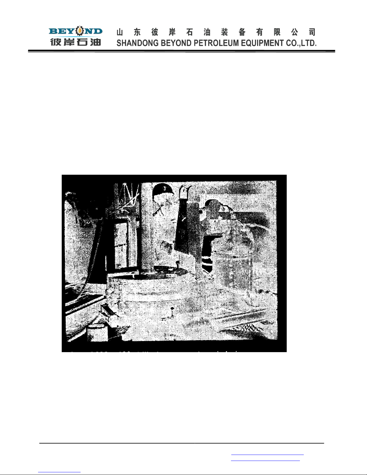
Fig.1 General View of ZQ203-100 Drill Pipe Power Tong
1 . floating body 21 . pneumatic tyre for low speed
2. die 22. low case body
3. inserts for jaws rack 23. sleeve
4. locating handle for the upper tongs 24. brake disc
5. pin 25. relief valve
6. sleeve 26. left- hand and right- hand screw
7. rotary 27. adjusting tube
8. adjusting bolts 28 . connecting rod
9. idler 29. jaw frame
10. gear 30. plug screw
11.suspension rod 31 . jaw
12. air pressure gauge' 32. brake band
13. bi-directional air valve 33 . door
14 . shockproof pressure gauge 34 . jaw pin
15. JML12-F08H oil motor 35. jaw roller
16. hand- reversing valve 36 . cam
17. inlet pipe 37. locating handle for low tongs
18. outlet pipe 38. air cylinder for gripping
19. sun- gear 39 . spring
20. pneumatic tyre for high speed 40. locating pin
41 . locating turning pin
General Description
ZQ203- 100 Drill Pipe Power Tong is a new type of mechanized tool on drilling
floor. Lanzhou Petroleum Machinery Research Institute and JIANGSU RUSHI
MACHINERY CO., LTD. (Pre-Jiangsu Rudong Petroleum Machinery Factory )
develop it, the tong is the combination of the upper tongs and low tongs. Open head
design allows the tongs to be on or off drilling pipe whenever necessary.
The tongs are first used in oil fields in 1981. It took 20 to 25 seconds to finish
an operation of making up or breaking out. Only one man is necessary to operate
the handle of hydraulic and pneumatic valves.
Crewmembers expressed their satisfaction that the operation is safe. Reliable,
lab our saving and preventing drilling pipes from banding. In addition, the torque is
controllable. Especially, It showed excellent performance in special operations such
as coring. Accident handling. Etc. The tongs has been used and got popularized in
ail oil fields in China and has achieve good results.
Special Features:
* The hydraulic power is only used to the hydraulic motor. all other mechanisms
are operated with pressurized air as power.

Add: No. 1201, E-commerce Building, Qingzhou City,
Shandong Province, China, 262500 Tel/Fax:
+86-536-3027478
山东省青州市开发区电商大厦
1201
号
Email: sales@sdbeyondpetro.com
Http:// www.sdbeyondpetro.com
*The upper tongs head can float in any direction and the low tongs are installed
in the case body.
* Shift of high and low speed with clutch without need to stop.
*The open throat of the gear can automatically restore its position
and align with the door of the tongs .
*An air cylinder is available to shift the tong onto or off the well
head without the heed of pulling or pushing the tongs by manpower.
* The suspensions hanger of the tongs is attached to one end of wire rope
recede through a pulley block that is fixed on derrick; the tongs can be adjusted to
any level by means of a hand hoist at an-other end of the wire rope.
* The deformation of the tongs head is restricted by means of the automatic
door of the tongs head at large torque (75 kN. m).
Fig. 2 ZQ203- 100 drill pipe power tong is being
Operated at well bore site

Add: No. 1201, E-commerce Building, Qingzhou City,
Shandong Province, China, 262500 Tel/Fax:
+86-536-3027478
山东省青州市开发区电商大厦
1201
号
Email: sales@sdbeyondpetro.com
Http:// www.sdbeyondpetro.com
1 . Functions
1.1 Hydraulic System
Rated flow 114 L/min
Max. Working pressure 16. 6 MPa
Electric motor power 30 kW
1.2 Pneumatic System 0. 5- 1 MPa
Working pressure
1.3 The speed of the tongs head at various flow see table 1 .
Table 1.Speed of the Tongs Head at Various Flow
Flow(L/min)
Speed of the Tongs Head r. p. m
High Speed
Low Speed
114
40
2.7
100
35. 1
2.4
90
31.6
2. 1
80
28
1.9
70
24. 5
1.7
60
21
1.4
1.4 The torque of the tongs head at various pressure see table 2.
Table 2.Torque of the Tongs Head at Various Pressure
Pressure of Hydraulic
System
MPa
Torque of the Tongs Head
(kN. m)
High Speed
Low Speed
16.6
10
100
15.0
9. 3
90. 5
13.O
8.5
81. 1
11.0
7. 7
68. 1
9.0
5. 7
53. 9
7.0
3. 9
41.7
5.0
3.0
29. 5
Assuming that:
1.4.1 Braking moments of brake band to the tong head is equal to 1 kN. m (the
effects of this moments have been allowed in Table 2. ) .

Add: No. 1201, E-commerce Building, Qingzhou City,
Shandong Province, China, 262500 Tel/Fax:
+86-536-3027478
山东省青州市开发区电商大厦
1201
号
Email: sales@sdbeyondpetro.com
Http:// www.sdbeyondpetro.com
1.4.2 The torque to make up (or break out) will increase due to rotational inertia
of the tongs head, but will decrease due to friction. To simplify calculation, data of
Table 2 are thought to be the result of the two kinds of torque canceling out each
other (actually, drill pipe can be tightened up with high speed torque due to
rotational inertia of the tongs head at rated speed).
1.5 Applicable Pipe O. D.
1.5.1 There are four sizes of the tongs head's laws for five sized pipe) . D.,
Jaws 8", 51/2", 5", 41/2", 31/2" for five pipe O. D. (each provided with five
sizes of rollers). They are 8", (φ203-φ183 mm) drill dollar, 51/2" (φ178-φ158 mm)
drill pipe joint, 5"(φ162-φ142mm) drill pipe joint, 41/2" (φ146-φ126 mm) drill pipe
joint, 31/2"(φ121-φ101 mm) drill pipe joint.
1.5.2 Max. Wear allowance is 20 mm for each size of drill pipe joint, eccentric
wear allowance is 5 mm.
1.5.3 The total length of drill pipe box and pin should not be less than 420 mm.
1. 6 Pneumatic cylinder for shifting the tongs
Max. stroke 1500 mm
Forward pushing force 2. 36 kN (p=O. 6 MPa)
Backward pulling force 1. 71 kN (p=0. 6 MPa)
1.7 Overall size and weight
The tongs (LxWxH) 1700 x 1000 x 1400mm (including the height of suspension
rod)
The tank (LxWxH) 1560 x 1060 x 1 190 mm
Weight of the tongs 2400 kg
Total Weight 4000 kg (including the tong and the tank)
2. Operation Range
2.1 In Tripping Operation
For drill pipe make up and break out when the torque is less than 100 kN. m
2.2 For Kelly joint make up and break out during drilling.
2.3 For 8" drill collar make up and break out.
2.4 For throwing off single.
To throw off single, adjust the suspension rod to keep inclination of the tongs
head corresponding to that of the mouse hole' s, vary the direction of the pneumatic

Add: No. 1201, E-commerce Building, Qingzhou City,
Shandong Province, China, 262500 Tel/Fax:
+86-536-3027478
山东省青州市开发区电商大厦
1201
号
Email: sales@sdbeyondpetro.com
Http:// www.sdbeyondpetro.com
shifting cylinder (use wire rope or cable attached to the derrick leg), to make the
tongs head align the mouse hole, then throw-off the single.
2.5 To keep rotation of drill string (bottom hole assembly) when rig is in trouble.
If transmission system of drilling rig is out of order. Draw works and rotary table will
not go on working, and drill string from sticking, removing the jaws from the low
tongs onto well head, an attached cable to both sides of the tongs end to prevent
the tongs from rotating. Then install the corresponding jaws into the upper tongs
according to the size of drill stem, let the laws engage with Kelly joint or drill pipe
joint, disengage the pin and clutch of rotary table and then operate the upper tongs
to drive drill stem of drill string rotating. The time to rotate drill string is well bore at
low speed (2. 7 rpm) should not be too long (usually less than half hour) .
3. Structure of Main Parts
3.1 Two-speed planet gear box
In order to achieve low torque spinning at high speed and high torque make up
or break out at low speed, the tongs is provided with a two- speed planet shift gear
and unique breaking mechanism for shifting the gear without stopping the tongs.
The efficiency of the tongs is therefore raised (Fig. 1 -3). See Fig. 3, high speed is
obtained as hydraulic motor drives planet gear(Z2) on the frame to rotate, power
comes from the sum gear (Z1) when the internal gear (Z3) is braked. For low speed,
the sequence is reversal, hydraulic motor drives the sun gear (Z6) to rotate, power
comes from the frame fitted with the planet gear (Z4) when the internal gear (Z5) is
braked.
3.2 Reducer Assembly Refer to Fig. 3, the output shaft of the two-speed planet
gear box is the input shaft of the two-speed gear reducer assembly, the notched
gear (Z11) is driven to rotate through the first step deceleration (ZI -Z8) and the
second step deceleration (Z9- Z10- Z11 ) . The function of two- idle gear (Z10) is to
keep the notched gear (Z11) rotating continuously by (Z9). This is necessary for
passing the notch.
3.3 The Tongs Head (See Fig. 1 )
3.3.1 Gripping mechanism: The notched gear(7) of transmission drives the
floating body (1) to rotate through three pins (5) . If brake band (32) continuously
prevents the brake disc from rotating with about 1 kN. m torque and the law rack
(29) with laws (31 ) is connected with the brake disc by screws , when the floating
body begins to rotate, both brake disc and the jaw rack is braked to stop because

Add: No. 1201, E-commerce Building, Qingzhou City,
Shandong Province, China, 262500 Tel/Fax:
+86-536-3027478
山东省青州市开发区电商大厦
1201
号
Email: sales@sdbeyondpetro.com
Http:// www.sdbeyondpetro.com
disc is not in touch with the tool joint. But the cam (36) with a fixed slope rotates
along with the rotation of the float body, the rollers (35) located at the back of the
jaw will go up along the spiral surface and comes close to the center along the
groove (E-E Turned), and at last grip against the drill string joint. Meanwhile the
notched gear will drive the brake disc, the jaw rack and the laws on the floating
body and drill string' to rotate for the operation of making up and braking out.
The lower tongs is to drive the jaw rack to rotate in the case body through air
gripping cylinder (38), thus gripping or loosening the joint beneath.
3.3.2 The floating body, owing to the relative position between the upper tongs
and the lower tongs is variable; it is necessary that upper tongs can float relatively
to the lower tongs.
3.3.3 The brake mechanism, in order to cause relative motion between roller
and cam (in the operation of making up and braking out), it is necessary to design a
brake mechanism of the law rack for every type of power tongs.
Refer to Fig. 1, the brake mechanism consists of the two brake bands round
the brake discs, connecting rod (28) and adjusting tube (27), the spring force of the
adjusting tube can be adjusted to change the value of braking moments by rotating
the adjusting tube. The brake mechanism can center the floating body with drill pipe
and meet the requirements of eccentric joint.
3.3.4 Restoration mechanism: There are three problems of restorations for
aligning notches to power tongs of open head, that is, the aligning of floating body
with the case body, the aligning of jaws rack of the upper tongs with the floating
body, and the aligning of laws rack of the low tongs with the case body. First, align
approximately with high speed, then align accurately with low speed, by this way,
the floating body can be aligned exactly with the case body.
The aligning of law rack of the upper tongs with the floating body is just the
same as the aligning of jaw rack of the lower tongs with the case body. Refer to B-B
turned of Fig. 1, pin (40) is fixed on the floating body, the locating turning pin (41)
connected with the locating handle (4) is fixed on the sleeve (23) of the brake disc.
Obviously, the floating body in the position as shown in Fig. 1 is capable of
relative motion to the right with respect to the brake disc, that is, to make counter
clockwise rotation (breaking out position). If the locating handle is reversely turned
180 degree, the floating body is capable of relative motion to left with respect to the
brake disc, that is, to make clockwise rotation (making up position). The brake disc
will be aligned with the floating body while the floating body is turned reversely until
the locating pin (40) is in touch with the locating turning pin (41 ) . In order to
observe conveniently, the position of the locating handle of the upper tongs should

Add: No. 1201, E-commerce Building, Qingzhou City,
Shandong Province, China, 262500 Tel/Fax:
+86-536-3027478
山东省青州市开发区电商大厦
1201
号
Email: sales@sdbeyondpetro.com
Http:// www.sdbeyondpetro.com
conform to rotational direction of make up (or break out). The position of the
locating handles for the upper tongs and the lower tongs should be the same. The
locating pin of the restoration mechanism for the lower tongs is fitted on the dial,
and fixed with bolts; other parts are fitted on the frame of the lower casing body.
3.4 Pneumatic System
As shown in Fig. 4, compressed air of drilling rig is used as the air source. In
order to prevent the harmful influence of the long distance airline on the airflow, the
tong preserves compressor air in the suspension rod, so the inner cavity of the
suspension rod is the reservoir (6) of the pneumatic system.
As shown in Fig. 4, the three reserving valves contro1 respectively the air tire
for high speed (1) and for low speed (2), air cylinder for shifting and cylinder for
gripping.
The air cylinder for shifting and the air cylinder for gripping have been shown
respectively in Fig.6 and 7.
3.5 Hydraulic System
In order to simplify hydraulic system, only the hydraulic motor uses hydraulic oil
as source power, see Fig. 5, hydraulic oil from oil tank (8) goes through oil pump (1),
filter (2) to handle-reversing valve (4), Hydraulic motor can rotate forward and
backward by controlling the hand- reversing valve. Overflow valve (7) is installed to
restrictions max. Pressure of hydraulic system. In order to keep hydraulic system in
low-pressure condition for making up, overflow valve (6) for making up is fitted. The
pressure for making up is adjusted to the valve of about 10 MPa. This is done
before leaving the factory. The working pressure can be found according to Table 2.
In order to clear away any impurities of hydraulic oil, filter (2) is fitted on the outlet of
the oil pump. Pressure oil goes through filter (2) to hydraulic motor. It is necessary
to clean or change the core of filter timely after working a period of time so as it can
be used continuously. There are two types of driving oil pump to be selected by
customers, one is driven by belts of air compressor of the rig (Fig. 8)and another is
electrically driven (Fig. 9). There are two types of hydraulic system to be selected
by customers, one is the constant displacement gear pump and another is variable
displacement plunger pump.

Add: No. 1201, E-commerce Building, Qingzhou City,
Shandong Province, China, 262500 Tel/Fax:
+86-536-3027478
山东省青州市开发区电商大厦
1201
号
Email: sales@sdbeyondpetro.com
Http:// www.sdbeyondpetro.com

Add: No. 1201, E-commerce Building, Qingzhou City,
Shandong Province, China, 262500 Tel/Fax:
+86-536-3027478
山东省青州市开发区电商大厦
1201
号
Email: sales@sdbeyondpetro.com
Http:// www.sdbeyondpetro.com

Add: No. 1201, E-commerce Building, Qingzhou City,
Shandong Province, China, 262500 Tel/Fax:
+86-536-3027478
山东省青州市开发区电商大厦
1201
号
Email: sales@sdbeyondpetro.com
Http:// www.sdbeyondpetro.com

Add: No. 1201, E-commerce Building, Qingzhou City,
Shandong Province, China, 262500 Tel/Fax:
+86-536-3027478
山东省青州市开发区电商大厦
1201
号
Email: sales@sdbeyondpetro.com
Http:// www.sdbeyondpetro.com
4. Installations and Commission
4. 1 Installation of Hydraulic System
4.1.1 Oil pump: Pay attention to installation of the electric system when oil
pump is electrically driven, the belt pulley should be aligned with driven pulley when
oil pump is belt driven by rig.
4.1.2 Pipe line, Take care that the pipe line is clean during installation, avoid
any damage of the four pipe lines leading to the tongs (high) pressure oil pipe line,
low pressure oil pipe line, pipe line for hydraulic motor relief and oil line) .
4.2 Installation of the tongs for a drilling rig (Fig. 10),
4.2.1 Fix the pulley 5 tons on the crown block beam.
4.2.2 One end of wire rope 5/8" to 3/4" is attached to the suspension hanger of
the tongs, another end of wire rope revved through the pulley and is connected with
the hanger of the hand hoist that infixed on the substructure barn. The level of the
tongs should be 40 mm above the working position of the elevator.
4.2.3 Installation of the fixing post (use 5 1/2" casing), The fixing post is
installed on the substructure. In order to prevent it from loosening and rotating
when in use, the bottom of the fixing post is welded to form a square, then make it
tightens byword wedge or by other way. The top of the fixing post is fixed on the
derrick with clip. The wellhead, the tongs and the fixing post should be in alignment
in installation.
4.2.4 The head of the shifting air cylinder is connected with the tongs. The fork
joint of the piston rod is connected with the fixing post with universal coupling.
Cylinder near the fixing post should be 100 -250 mm lower than the end near the
tongs.
4.2.5 In order to keep the tongs away from the wellhead automatically (when
compressor air isn’t available) it is convenient to install a right-hand and left-hand
threaded rod near the racking platform for pulling the tongs backward.
4.3 Installation on another drilling rig (Fig. 11):
This drilling rig has a larger drilling platform, the derrick is type "A", the tong
may be installed near the cathead weld a short sleeve on the substructure instead
of original fixing post. The shifting air cylinder is placed in back end of the tongs, the
end of the shifting air cylinder near the tongs is 100-200 mm higher than another
end by.
4.4 Leveling the tongs, Leveling the tongs is very important to its application if

Add: No. 1201, E-commerce Building, Qingzhou City,
Shandong Province, China, 262500 Tel/Fax:
+86-536-3027478
山东省青州市开发区电商大厦
1201
号
Email: sales@sdbeyondpetro.com
Http:// www.sdbeyondpetro.com
the tongs is not level, not only slip will take place but also damage will occur.
After finishing the connection of pipeline, the shifting air cylinder is connected
with the tail of the tongs. Turn on the air valve and shift the tongs to the well head
(in the well head should be a drill pipe for leveling). Adjust the level of the tongs until
the bottom of the tongs is 40 mm above the top surface of the elevator. After the
notch of the tongs goes on to the drill pipe, observe in the front of the tongs head
whether the left or the right side of the tongs is horizontal, if not, rotate the thread
rod suspension rod to change the position of suspension wire rope for leveling.
After it is nearly leveled, observe whether the two plug screw (serial number is 30 in
Fig. 1) of the upper and low tongs contact closely to the pin and box of drill pipe
respectively. If one is not, the tongs is not horizontal. By this way, adjust the
adjusting bolts (serial number is 8 in Fig. 1) of the suspension rod so that the pin
and box of drill pipe can contact closely to the two-plug screw of the upper and low
tongs respectively. Generally, it is all right when the top surface of the tongs is
parallel to the surface of rotary table.
4. 5 Commission,
4.5.1 After finishing the connection of pipe liner, operating the air valves of
high and low speed.
The gripping air cylinder of the lower tongs and the shifting air cylinder to see
whether the valves are working well and whether there is any leakage.
4.5.2 Let the tongs idle for 1-2 minutes with low speed, the pressure for idling
at low speed is within 2.5 Mpa.
4.5.3 Let the tongs idle for 1-2 minutes with high speed, the pressure for idling
at high speed is within 5 MPa.
4.5.4 Run the motor forward and backward and test the restoration mechanism
of the tongs head.
4.5.5 Shift the tongs onto wellhead and grip the joint with the low tongs.
Testing the pressure of making up and braking out with high speed (do not with
low speed to prevent joint from damaging), and adjust the pressure of making up
with the overflow valve for making up and the pressure of breaking out with main
overflow valve to meet the requirement of the well.

Add: No. 1201, E-commerce Building, Qingzhou City,
Shandong Province, China, 262500 Tel/Fax:
+86-536-3027478
山东省青州市开发区电商大厦
1201
号
Email: sales@sdbeyondpetro.com
Http:// www.sdbeyondpetro.com
Fig.10 Installation on another drilling rig

Add: No. 1201, E-commerce Building, Qingzhou City,
Shandong Province, China, 262500 Tel/Fax:
+86-536-3027478
山东省青州市开发区电商大厦
1201
号
Email: sales@sdbeyondpetro.com
Http:// www.sdbeyondpetro.com

Add: No. 1201, E-commerce Building, Qingzhou City,
Shandong Province, China, 262500 Tel/Fax:
+86-536-3027478
山东省青州市开发区电商大厦
1201
号
Email: sales@sdbeyondpetro.com
Http:// www.sdbeyondpetro.com
5. Adjustment of torque and speed of tongs heads.
5.1 The speed of the tongs, the speed of the tongs head is proportional to the
flow of oil pump sup-ply. It is adjusted before delivery.
5.2 The torque of the tongs head, the torque of the tongs head is proportional
to the pressure of hydraulic system. To adjust it, shift the tongs onto well head to
hold the joint, operate the tongs with high speed to make up until the tongs head
stop rotating, turn off the overflow valve for making up, adjust the overflow valve of
the oil tank to a set pressure (that is a set torque), than turn on the overflow valve
for making up and adjust the pressure of making up to the set valve (i. e. to the set
torque of making up).
Note: Don' t adjust the pressure at low speed, because the torque of low speed is
too large, it will cause damage of the joint.
6. Operating Regulations.
6.1 Turn on the valve of airline from drilling rig to the tongs. (Put the valve on
driller' s console if possible)
6.2 Start oil pump and turn on the one-way air valve to make the oil pump run
idly, meanwhile, the reading of the pressure gauge should not exceed 1. 5 MPa.
6.3 Check on whether the size of jaw is in correspondence with the size of dril1
pipe sub. If it is put the two locating handles (serial numbers are 4, 37 in Fig. 1) to
the position according to making up or braking out.
6.4 Operate the bi-directional air valve of the shifting air cylinder to move the
tongs to well head smoothly, do not turn on the air valve completely, otherwise, the
tongs will quickly move to wellhead and lead to an impact. If the level of the tongs is
wrong, operate the 3t hand hoist to adjust it to a suitable position.
6.5 After the drill pipe goes into the notch of the tongs head, observe whether
the two plug screws of the upper and lower tongs are contacting closely to the pin
and box of drill pipe respectively, then operate the bi -directional air valve of the
gripping air cylinder to make the lower tongs to hold the joint, put the handle of the
bi-directional air valve to "O" position and release the air.
6.6 According to the need of making up and breaking out, put the handle of the
bi - directional Air valve to relevant position, there is no necessary to shut down in
changing speed.
6.7 Operate type "H" hand- reversing valve to control the motor running forward
and backward, change the position of hand- reversing valve according to the need

Add: No. 1201, E-commerce Building, Qingzhou City,
Shandong Province, China, 262500 Tel/Fax:
+86-536-3027478
山东省青州市开发区电商大厦
1201
号
Email: sales@sdbeyondpetro.com
Http:// www.sdbeyondpetro.com
of making up or breaking out.
6.8 Restoration: This is the procedure that the notches of the tongs head are
aligned with each other. Having finished one make up or one break out, it is
necessary to operate the type "H" hand-reversing valve to make the tongs head
rotate against the working direction of the tong head. Operate the bi - directional air
valve according to the distance among each of the notches in restoring use high or
low speed to bring about restoration. The type "H" hand- reversing valve should be
used as rarely as possible for high speed to restore and the bi-directional air valve
should be used skillfully to reduce an inertia shock.
6. 9 In breaking out, when pin is spinned out from box completely (i. e. drill pipe
rotates reversely for five and half turns or the sound of drill pipe falling down is
heard after broken out) turn the handle of the bi -directional air valve towards the
direction of making up to restore. When the upper tongs have loosened the drill
pipe but the notches is still not aligned, it is also permitted to hoist a stand when the
tong is shut down. After hoisting, the stand proceeds to restore again, this
procedure will save time.
6.10 Before the pin has not spinned out of the box completely don 't hoist drill
pipe upward to pre-vent drill string from falling down to hole bottom. Before the
upper tongs has not loosen the drill pipe, it is not permitted to hoist the drill pipe to
prevent the floating body front bringing out of the tongs or drill pipe from falling
down to make damage of the parts.
6.11 Operate the handle of the bi-directional air valve of gripping air cylinder to
the position opposite the working position to make the lower tongs restore "0"
position and align the notches.
6.12 Operate the handle of the bi- directional air valve of the shifting air
cylinder to move the tongs out of wellhead smoothly.
6.13 Having finished whole trip, put all hydraulic and air valves to "0" position,
turn or one-way valve, oil pump and the valve of air line from drilling rig to the tongs.
6.14 When the drilling rig is moved to other place, all the bare joints of
hydraulic and air lines should be sealed up to prevent dirt from entering into
hydraulic and air lines.
6.15 The position of the locating handle of the upper and low tongs should be in
accordance with making up or breaking out. In changing their position, it is not
permitted to operate it until each of the notches of the tongs is aligned, otherwise
the mechanism will be out of order.

Add: No. 1201, E-commerce Building, Qingzhou City,
Shandong Province, China, 262500 Tel/Fax:
+86-536-3027478
山东省青州市开发区电商大厦
1201
号
Email: sales@sdbeyondpetro.com
Http:// www.sdbeyondpetro.com
7. Maintenance
7.1 Set up a system of personal responsibility.
7.2 According to the working condition of the filter of hydraulic system, it is
necessary to clean or change its core timely to prevent the core from plugging up by
dirt to affect its normal use.
7.3 After a new tongs is used, hydraulic oil should be changed (or settled)
within one month. The oil level of the tank should be kept above the lower limit line;
otherwise, oil should be filled up promptly. When supplying oil to the tank, prevent
impurity from coming into it.
7.4 After finishing every trip, the tongs head should be washed clean with water,
and be blown dry with compressed air. In winter blow with steam. After the cam
(serial number is 36 in Fig. 1) and roller parts are cleaned up, coat their surface with
grease .the cam should be clean and the roller pin' should be able to restore freely.
7.5 After every three wells completed, change the engine oil in the gearbox and
the molybdenum disulfide lubricant in the transmission box once (well depth is
considered as 3, 000 meters).
7.6 Maintenance requirement of the bearings in transmission system is the
same as bearings in air compressor.
7.7 After every trip, clean the shifting and gripping sir cylinder with clean water,
and wipe the piston rod dry with cotton yarn and coat its surface with grease, its
extended parts should be drawn in its cylinder completely.
7.8 After every trip, inject 50 ml clean engine oil into the air valve to lubricate all
parts of the airline and to prevent rust.
7.9 Other grease nipples are as follows,
Position
Quy
Period
Spleen shaft
1
Inject grease before every
trip
Gripping air cylinder brace
2
Ditto
The end of idle shaft
2
Ditto
Bearing house cover of oil
tank
2
Ditto
This manual suits for next models
1
Table of contents
Popular Power Tools manuals by other brands

Milwaukee
Milwaukee 2860-20 Operator's manual

Hitachi
Hitachi C18DLP4 - 18V Li-Ion 6-1/2" Circular Saw Safety instructions and instruction manual

Powermatic
Powermatic 720HD Operating instructions and parts manual

Fein
Fein AFMM 18 manual

ABB
ABB SACE Emax 2 Installation, operation and maintenance instructions

Sealey
Sealey POWER TOOLS CP3002 instructions