BEZIOR XF800 User manual

E-BIKE USER’MANUAL XF800
CAUTION: READ THIS MANUAL BEFORE USING YOUR EQUIPMENT


1
Congratulations
First of all, congratulation on your purchasing of our electric bicycle,it is a carefully designed and
manufactured under strict quality control.
Please read this instruction manual carefully and thoroughly before riding, as it contains sufficient
information, which is very important in safety, maintenance and simple assembly. It is the owner's
responsibility for reading this manual before riding this bike.
The user's instruction manual if for outside battery model and inside battery model electric bike which
includes two sections, one is mechanical section, and another is electric section. This instruction is applied
to the electric bikes with following equipment:
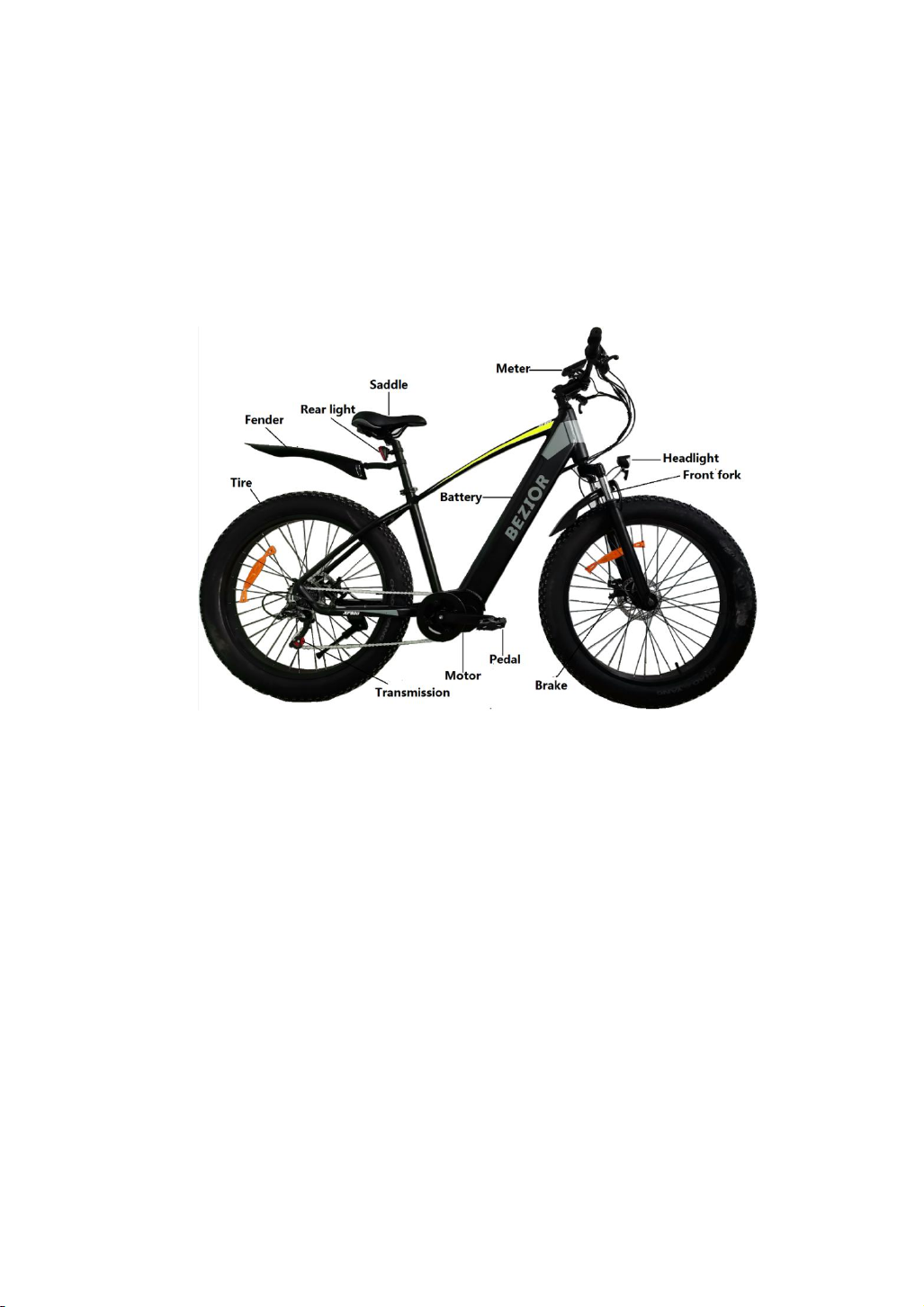
For mechanical equipment:
Derailleur/disc brake/Internal gear hub ;
For mechanical equipment, an electric bicycle differs only slightly from a non-electric bike.
For electric equipment:
The battery-pack on the down tube .
The motor in the middle drive.
The controller is embedded in the motor .
Operation panel is installed to handle bar.

2
SECTION I
MANUAL FOR MECHANICAL PARTS
Contents:
Conditions for Riding This Electric Bicycles
Selection and Set-up
Safe Cycling and Safety Tips
Routine Maintenance Check and Lubrication
Assembly Instructions
1.
Conditions for Riding this Electric Bicycles
This electric bicycle is designed for riding on a road or a paved surface where the tires do not lose ground
contact, and this electric bicycle must be under proper maintained according to the instruction of this
manual. The maximum weight of the rider and load is required to be less than 200lb (or 90kg).
Warning: You are warned that you take the consequences such as personal injury, damage, or
losses.
2.
Selection and Set-up
2.1Saddle and Handlebar Stem Adjustment
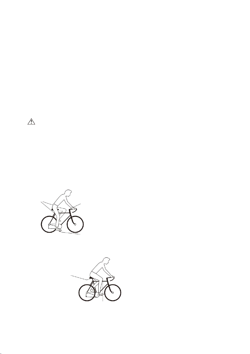
The seat can be easily moved either up or down. Adjust the seat to keep the rider's knee maintaining a
slight bend when his foot is in the lowest pedaling position(refer to fig. 1). Handlebar stem is
approximately on the same level as saddle or slightly lower. For some more adjustment tips, please refer
to fig. 2 as below:
Knees slightly bent Handlebar Stem approximately
level with seat or slightly lower
Pedal at bottom position
Fig.1
Loosen saddle from seat pillar to adjust forwards
or backwards. Tighten when set correctly
Fig.2
The saddle should be moved forwards or backwards so that
the knee is directly above the pedal when the crank is parallel to the ground.

3
Warning: If your seat post is not inserted up to the minimum insertion mark, the
seat post may break (refer to fig. 3)
Once the saddle is at the correct height, make sure the seat post should be up to
its minimum insertion mark.
Minimum Extension Mark (Fig.3)
Warning: handle stem minimum insertion mark on traditional quill stems must not be visible above the
top of headset.If the stem is extended beyond the minimum insertion mark the stem may break or
weaken the fork steering tube.
3. Safe Cycling and Safety Tips
3.1 Checking Points Before Riding
Before you ride your electric bicycle at any time, make sure it is in a safe operating condition. Particular
check the following items:
Electric bicycles nuts, bolts, quick-release and parts are fastened tight and no worn or damage;
Riding position is comfortable;
Steering is free with no excessive play;
Wheels run true and hub bearings are correctly adjusted;
Wheels are properly secured and locked to frame/fork;Tires
are in good condition and inflated to correct pressure Pedals
are securely tightened to pedal cranks
Gears are correctly adjusted
All reflectors are in position
After you have made any adjustment to your electric bicycle, check that all nuts and bolts are securely
tightened and cables are free from kinks and fixed securely to the electric bicycles frame. Every six months,
your electric bicycle should be professionally checked to ensure that it is in correct and safe working order. It
is the responsibility of the rider to ensure all parts are in working order prior to riding this electric bicycle.
3.2 Do Not When Riding
Do not ride without wearing an approved helmet, which must meet European standard or the same effect
(comply with the law, rule or regulations in your local area);
Do not ride on the same side of road as oncoming traffic;
Do not carry a passenger unless the cycle is equipped to do so;
Do not hang items over the handlebars to impede steering or catch in the front wheel;
Do not hold on to another vehicle with another hand;
Do not ride too close to another vehicle.

4
Warning of Wet Weather Riding: No brakes work as well under wet or icy conditions as they do
under dry conditions. The braking distance in wet weather would be longer than those in dry, and you
should take special precautions to assure safe stopping. Ride than normal and apply your brakes well in
advance of anticipated stops.
Warning of Night Riding: we recommend you minimize the times you ride after dark. If you
have to be out on your electric bicycle at night, you must comply with the relative law, rule or
regulations in your local area, using a headlight(white) and taillight(red) on your electric bicycle in
addition to the all-around reflectors fitted. For more safety, wear light colored clothing with reflective
stripes. Check that the reflectors are firmly secured in the correct position and clean and not obscured.
Damaged reflectors must be replaced immediately.
4.Routine Maintenance Check and Lubrication
A-Headset
Remove, clean and regrease
bearing yearly, checking if
replacements required.
H-Mudguards
Check the mudguards are
clean and tight. Ensure the
mudguards are secure and
undamaged. Replace if
necessary.
O-Bottom Bracket
P- Clean,regrease yearly
checking for wear.
B-Stem Nuts
Ensure stem nuts and bolts
are tight
I-Quick release
Check the quick release is
tight, ensure the mudguards
are secure and undamaged,
replace if necessary
P-Gears
Front and Rear Lightly oil
moving parts. Maintain
adjustments of front and rear
derailleurs.
C-Handlebars
Check handlebar bolt is tight.
Check brake lever securely
mounted to bars and brakes
stop smoothly and efficiently.
J-Wheel Hubs
Grease bearings monthly.
Adjust cones to avoid free
play side to side.
Q-Chain cover
Check the chain cover is
secure and undamaged,
replace it if necessary

5
D-Brakes
Lightly oil exposed cables
monthly. Maintain adjustment
and replace brake blocks
when worn, brake cables
when frayed.
K-Reflector(Pedal)
Check all fitting are secure.
R-Seat and Stem Nuts
Be sure seat and stem nuts
are tight
E-Battery light (front and
rear)
Ensure the front and rear
battery light are secure and
undamaged. Replace if
necessary.
L-Cranks
Grease bearing monthly,
check
that axle bolts and cotterpin
bolts are tight, check for free
play in bottom bracket.
S-Pedals
Lightly oil bearings monthly
F-Front suspension unit
Dealer adjustment only
M-Chain
Keep light oiled weekly, clean
and lubricate half yearly.
G-Tyres
Check for cuts and wear,
Maintain pressure indicated
on tires wall for maximum
Efficiency.
N-Wheels
Check that axles are sealed
and secured properly. Rim
should be kept free from wax,
oil, grease and glue. Check
for loose or missing spokes.
(see warning below)
U-The electrical parts
V-you can refer to the manual
for the electrical parts.
Warning: As with all mechanical components, the bicycle is subjected to wear and high
stresses. Different materials and components may react to wear or fatigue in different ways. If the
design life of a component has been exceeded, it may suddenly fail possibly causing injuries to the
rider. Any form of crack, scratches or change of coloring in highly stressed areas indicate that the
life of the component has been reached and it should be replaced.
Warning: It is important to use only genuine replacement parts for several safety-critical
components.
4.1To keep the electric bicycle functioning well, the following routine maintenance and lubrication is
necessary for you.
Half Yearly - Remove and clean, lubricate chain, derailleur gears and all cables. Check and replace
as required.
NB - Wash cycle weekly with warm soapy water and dry it by rubbing with a soft cloth.
Warning: When the rim becomes part of the brake system , it is very important to check the rim
wear monthly and adjust the brake shoes accordingly to make the clearance at 1-1.5mm from the track
of rim. The wear of rim may destroy the braking and result in personal injury to the rider or others.

6
5 .Assembly Instruction
Here is some important information for electric bicycles assembly, which is very useful for your maintaining your
electric bicycle, and especially helpful when you purchase our e-bikes which is partly assembled and packed in a
carton.
Step 1: Preparation:
Take the electric bicycle and parts out of the carton and detach all parts that are tied to the frame. Be careful not
to scratch the frame or cut the tire when removing the wrapping. And please do not rotate the handlebar either
until disassembly, otherwise it may break the cables. Then carefully examine the carton for loose parts and make
certain that no parts are left.
Step 2: Seat Assembly (refer to fig.4)
1)
Loosen the seat clamp nuts(both sides)
2)
Insert the seat post into the seat clamp. The seat post must extend at least 1/4 inch(6-7mm) above the top
edge of the seat clamp.
3)
Re-tighten the seat clamp nuts on both sides(hand tight).
4)
Push the seat post into the seat tube of the electric bicycle frame and rotate the seat until the tip of the seat
is directly above the top tube of the frame.
Tip of Seat
Seat Clamp
seat Clamp Nut
Seat Post
Minimum Insertion Line
Top Tube
Seat Tube Seat Post Binder Bolt and Nut fig.4
THE SEAT POST MUST BE INSERTED INTO THE SEAT TUBE AT A DEPTH WHERE THE MINIMUM INSERTION
LINE IS NOT VISIBLE!!!
5)
Open the seat post quick release lever(Fig. 5). Insert the seat post into the seat tube to a
sufficient depth so that the minimum insertion line is no longer showing.
Fig 5 Opening and adjusting a quick release
Adjustment
Nut
Closed
Opean

7
6)When you are satisfied with the height of the seat post, close the sea post quick release lever. The
tightness of the lever is adjusted by rotating the adjustment nut opposite the quick release lever. Turn the nut
by hand to adjust the tension while holding the lever stable.
Step 3: Handlebar & Handlebar Stem Assembly(refer to fig. 6 and 7)
Expander Bolt
Handlebar Clamp Bolt
Handlebar Stem
Reflector
Fork Tube
Expander Wedge
Fig.6 Fig.7
As an usual situation, in our factory, the handlebar have been pre-assembled together with brake levers,
shifter levers and grips. Be sure that the longer cable is fixed to the right lever (rear brake) and shorter
cable to the left (front brake), or according to your local rule and practice (Note: In some area, such as UK,
the cables are required to be arranged in the opposite way).
Since your cycle may be fitted with an adjustable, a standard stem or an A-head stem(refer to fig.6 ), you
must always check that all the bolts are tight before cycling. Based on the situation of standard handlebar
stem, please follow the instruction below:
1)
Push the handlebar stem into the fork tube (head of the frame ) to the minimum height line that is
marked on the side of the handlebar stem. It might be necessary to loosen the expander bolt so that the
stem can slide into the fork tube, until you get your desired height of the handlebar stem.
2)
Align the handlebar stem with the front wheel(see fig.7). Tighten securely the expander bolt with
an adjustable wrench.
Note: Some models require a 6mm allen key.(Tightening torque: 18N.m or 14 foot lbs.torque)
3)
Loosen the handlebar clamp bolt and nut from the stem.
4)
Position the handlebar at the desired angle. Make sure that the stem is in the center of the
handlebar
5)
Tighten securely the handlebar clamp bolt (Tightening torque: 18N.m or 14 foot. lbs)
6)
Be sure that your handlebar and stem assembles are properly tight before riding. The
handlebar should not rotate in the stem. When you straddle and grip the front wheel between
your knees, the handlebar should not be able to turn when you apply pressure horizontally. Refer
to (fig. 7).
Note: Under the situation of A-head stem, you make the similar operation as the above.
Compression bolt tightening torque: 23N.m or 17 foot lbs. torque; stem clamp bolt tightening
torque: 12N.m or 9 foot. Lbs
Handlebar
Front Wheel
Center line

8
Step 4 Attaching Pedals(refer to fig. 8) :
1)The pedals are marked with either a “R” or “ L” on the threaded end of the pedal axle.
2)Screw the pedal marked ”R” into the right side of the crank assembly (chain side of electric bicycles).
Turn the pedal (by hand) in the clockwise direction. Tighten securely with an adjustable wrench or the
plate wrench special for pedals(Tightening torque: 34N.m or 26foot.lbs).
3)Screw the pedal marked “L” into the left side of the crank assemble. Turn the left pedal (by hand) in
the counterclockwise direction. Tighten securely with an adjustable wrench or the plate wrench
special for pedals(Tightening torque: 34N.m or 26foot.lbs)
PEDAL IDENTIFICATION
fig. 8 Attaching pedals
Step 5 Front wheel installation:
1)Cut the wrapping rope, remove the front wheel, remove the front fork protection lever and the
front wheel protection cover.
2)Make sure that the front wheel is in line with the rear wheel, then start installation. First pull the
wheel upwards, put the disc brake pad into the front brake caliper, and then use 15 wrench to tighter the
front hub fixing screw.
3)Adjust the adjusting screw of the disc brake to make the disc brake rotor without obvious friction
Step 6 Brake Adjustments:
The brake on your electric bicycle should have been adjusted correctly in our factory, however, as cables
do stretch, it is important to check the adjustment of your brakes after your first riding. Most brakes will
need some adjustment after being used a few times.
6.1 Basic Disc Brake Adjustment
The notes that follows are not exhaustive. If you need further assistance, please take your cycle to your
local dealer or a professional cycle shop.
a. Brake Lever and Brake Pad Travel Adjustment
You can alter the amount of braking pressure by altering the travel of the brake lever and by the proximity
of the brake pads to the brake disc.

9
To alter the travel of the brake lever adjust screw A (see fig. 9), unscrew screw A reduce the amount of
lever travel and by tightening it increase the lever travel. If you have fully unscrewed screw A and the lever
travel is still excessive you will have to adjust the space between the pads and the disc.
Fig.9 Brake Lever Adjustment
Tighten screw A (Fig.9) up to the brake level. Go to Fig.11 and insert an allen key into the smaller hole
inside allen key hole B. Rotating the allen key clockwise pushes the outer brake pad forward by
approx.0.8mm After each turn, check the braking performance.
B
smaller keyhole inside main hole
Fig.11 Disc brake pad adjustment Fig 12 Disc brake pads adjustment
Once the correct amount of travel has been reached, centre the brake Calliper on the disc by adjusting
screw C(Fig.12).when the brake pads are centered on the disc the wheel should spin freely, though there
may be a slight amount of noise until the pads “bed” in.
If your cycle came from, or has recently been overhauled by a professional repair shop. you should be able
to maintain good braking performance by adjuster screw C ( refer to Fig.12)
Once the correct amount of travel has been reached, center the brake caliper on the disc by adjusting
screw C (fig.12). When the brake pads are centered on the disc the wheel should spin freely, though may
be a slight amount of noise until the pad bed in.
b.Brake pad wear and replacement
When you check your brake pads due to falling performance, check their thickness. If they are less than 1
mm (Fig. 13), they will need replacing.
Fig.13 Fig.14
C

10
To fit new pads, remove the brake calliper from the fork or frame by unscrewing allien bolts D(Fig.14).
Unscrew (anti-clock wise), the smaller allen bolt inside allen bolt B(Fig.11). Lift up and pull the inner pad
downward, using the protruding part. Slide a thin slot screwdriver under the outer pad and lift it up. Hold
the screwdriver in this position and remove the pad with a pair of long nosed pliers.
Remove the springs from the worn out pads and fit them onto the new pads. Replace the new pads,
keeping them slightly inclined into the seat of the Caliper. Check that the spring hooks correctly onto the
small piston.(When pulling downwards the pads should not come out).Refit the Caliper to the fork or frame
and adjuster screw C(Fig.12)until the pads and the disc are centered and the wheel spins freely. Again there
may be some noise from the brake until it “bed” in.
Step 7 Derailleur Gears Maintenance and Adjustment
To ensure that your derailleur gear works efficiently and to prolong its life, it must be kept clean and free
from excessive dirt built up and should be properly lubricated.
Note: If the specific instruction manual is provided accompanied with your bike, please follow it.
Before Adjustment, please make sure of the following details:
The right shifter controls the rear derailleur and sprocket.
The largest rear sprocket generate low gear for hill climbing; the small rear gear sprocket develop high
gear ratios for speed work and downhill riding.
The small chain ring produce low gear ratios while the larger front chain ring produce high gear
ratios
To operate your derailleur gear system efficiently and reduce damage, wear and reduce noise to a
minimum, avoid using the maximum crossover gear ratios of large chain ring/large rear sprocket, small
chain ring/small rear sprocket
Note: For positive gear selection, observe these four precautions
1) change only when pedals and wheels are moving in a forward motion
2) reduce pedal pressure while changing gears
3) Never back pedal when changing gears
4) Never force the gear levers
7.1Rear Derailleur Adjustments:
Move the shifter all the way forward (toward seat) and with the chain on the smallest rear sprocket and
largest front sprocket, check for cable slack at point “B” . If there is slack, loosen the cable nut or screw, pull
on the cable end with pliers and retighten the cable nut or screw while pulling cable taut(tightening torque:
5-7N.m or 4-5foot.lbs)
7.2 Top Adjustment
Turn the “H” adjusting screw(or top rear adjustment screw) on the gear mechanism so that, looking
from the rear, the guide pulley is below the outline of the top gear.

11
7.3 Low Adjustment
Turn the “L” adjusting screw (or low gear adjustment screw) so that the guide pulley moves to a position
directly below the low gear.
operate the shifting lever to shift the chain from top gear to 2nd gear.
If the chain will not move to the 2nd gear, turn the cable adjusting barrel to increase the tension 1(counter
clockwise).
If the chain moves past the 2nd gear, decrease the tension 2(clockwise)
Next, with the chain on the 2nd gear, increase the inner cable tension while turning the crank
forward. Stop turning the cable adjusting barrel just before the chain make noise against the 3rd
gear. This complete the adjustment Be sure to perform oil maintenance at each part of the
transfer mechanism. The optimum oil is dry molybdenum oil or the equivalent.
The back derailleur :
Step 8: Tighten the front and rear hubs nuts securely.(Tighten torque: about 30 N.m for front wheel, about
25 to 30 N.m for rear wheel )Before riding, lift the front of the bicycle so that the front wheel is off the
ground and give the top of the tire a few sharp downward strikes. The wheel should not wobble or come off
Step 9 Tire inflation instruction:
9.1 After the bicycle is assembled, please check whether the air pressure of the front and rear tires is within the
normal value.
9.2 When refilling tires, you must refer to the inflation reference range on the side of the tire for refilling,
generally between 20PSI (140Kpa).

12
SECTION II
MANUAL FOR ELECTRIC PART
The model instructed in this manual is made with “start aid”. This electric assistance system will help
riders to save their energy, while they enjoy their easy sports.
Here is the function of so-called “start aid”: when you long press the down button for display for seconds,
the bike can be started at speed of 6 km/h. After the bike moving forward, you can easily pedal on and
release the “start aid” button.
Also, you can pedal 3/4 round of the chain wheel to start motor without using the “start aid” button.
Content
1.
Important Safety Cautions
2.
Meter Operation
3.
Using and Charging the Battery
4.
Meter operation
5.
Using and Maintaining the Electric HubMotor
6.
Maintaining the Controller
7.
Simple Trouble Shooting
8.
Diagram and Specification
1.
Important Safety Cautions:
We strongly advise wearing an approved helmet, which meet European Standards.
Obey local road rules when riding on public roads.
Be aware of traffic conditions.
Parents need to ensure their children are supervised when riding any bicycle equipment.
Have your bike serviced only by local authorized bicycle shops. Regular servicing will ensure a
better and safe riding performance.
Do not exceed more than 90kg load on bicycle, including rider.
Do not “dink” or have more than one rider at a time on the bicycle.
Ensure regular maintenance is carried out on the bike according this owner's manual
Do not open or attempt to maintenance on any electrical components.
Contact your local bicycle agent for qualified service and maintenance if needed.
Never jump, race, perform stunts or abuse your bicycle.
Never ride under the influence of intoxicating drugs or alcohol.
We strongly recommend switching-on the lighting system, when riding in the dark, fog or poor visibility.
When cleaning this bike, please wipe surface with a piece of soft cloth. For the very dirty spot, you can
wipe it with a little neutral cleaning agent.

13
Warning: Do not wash this electric bike direct with spraying water, to avoid water entering electric
components, which may result in damage of the electric components and then, the electric assistance bicycle
can not be normally used.
2.
Operation
Your new electric bicycle is a revolutionary transporting means, applied with alloy aluminum frame, Lithium
battery, a super high efficient electric hub motor and controller with pedal assistance system, to make easy
biking. The above mentioned equipment will ensure high safe riding with excellent performance. It is
important for you to learn the following guideline in order to get the best possible experience with your
electric bicycle.
2.1
Checking Before Riding
2.1.1
please ensure tires are fully inflated to 45psi, before riding. Remember, performance of the
bike is directly related to the weight of the rider and baggage/load, together with the stored energy
in the battery;
2.1.2
Charge overnight, prior to riding the next day;
2.1.3
Apply chain oil periodically and clean if dirty or gummed up, using a degreaser, then wipe
clean and oil bicycle chain again.
3.Switching on the battery
3.1This battery is inside the lower tube,and can be taken out easily .It is necessary to insert the key into the
keyhole of the lower tube and take out the battery .
3.2 Procedure for Charging
Please charge the bike battery according to the following procedure:
3.2.1 Make sure the display is turned off. Then open the charging socket cover, which is situated at side
of battery.
3.2.2 Insert the charger output plug into the battery securely and then, plug the main cable of the
charger into a reachable AC outlet;
3.2.3 When charging, the LED on the charger will become red, showing the charging is on. It becomes

14
green, after the battery is fully charged.
3.2.4 To finish charging, you must disconnect the charger input plug first from the AC outlet, and after
that, disconnect the charger output plug from the battery .Finally, close the cover on the charging
socket and check the socket, if covered for sure!
Warning:
1) You should only use the charger provided with the electric bike, otherwise damage could occur to
your battery and void the guarantee.
2) When charging, both battery and charger should be minimum 10cm away from the wall, or under a
condition of ventilation for cooling. Place nothing around the charger, while in use!
3.3 About battery charging :
Before using the bike for the first time, fully charge the battery.
A normal charge lasts 6-8 hours (for bikes with battery with capacity of 13Ah).
The charger port is positioned at the left side of the battery
If required, battery can be removed from the bike.
First, be sure the bike is turned-off.
The display must be off .
The battery light must be off.
insert the key in the lock and turn it to unlock the battery box.
4.Meter operation:
4.1 Meter Instruction (For LCD display ):
Noted:When the meter is turned on ,press and hold the "+" button for 3 seconds to turn the headlight
and the meter background light on, and repeat operated to be turned off .

15
4.2 Meter operation:
If you don't need the electric power assistance, you need to turn off the meter.
4.3 6km/h assistance function
When the bike is stopped and the display is turned-on, hold the DOWN key to activate the speed function
of 6Km/h.
This function is useful when user must push the bike by hand on a climb or on uneven terrain.
Do not use this function when riding the bike.
If pushing faster than 6km/h, the function automatically deactivates.
Be careful when this function is turned-on.
4.4 Advantages of a Lithium Battery
Your electric bicycle is equipped with high quality lithium batteries, which are light and create no pollution to the
environment, as a typical green energy source. As well as the above features, the lithium batteries have the
following advantages:
Operating instructions
To switch
on/off the
E-Bike
system,
hold the
Button
for 3s.
The system
default
value is "1"
low speed.
(Pure
electric
Press “+” to
increase to
“2”
low-mediu
m speed.
(Pure
electric
mode+assis
t mode)
Continue
to press
“+” to
increase to
“3”
medium
speed.
(Pure
electric
mode+assis
t mode)
Continue
to press
“+” to
increase to
“4”
medium-hi
gh speed.
(Pure
electric
mode+assi
st mode)
Continue to
press “+” to
increase to
“5” high
speed. “5”
gear is the
highest
speed in
bike. (Pure
electric
mode+assist
mode)
Press “-” to
decrease to
“0” peed
while the
system is
on,Pure
electric
mode and
assist mode
will be
turned off.

16
charging without memory effect
big electric energy capacity, small volume, light in weight, with large current output,
suitable for high power vehicles.
long life
A wide working range of temperature: -10°C
5.Using and Maintaining the Electric Hub Motor.
To avoid damaging the motor, it is better to start the motor working after the bike has been
pedaled from standstill. Under usual condition, our intelligent e-bikes are programmed in our factory,
to start the electric assistance when pedaling 3/4 circle of the chain wheel.
Do not use the bike in a rainstorm or thunderstorm. Nor use the bike in water. Otherwise, the
electric motor may be damaged.
Avoid any impact towards the hub motor, otherwise, the casting alloy aluminium cover and
body may break.
Make regular check on the screws on both sides of the hub motor, fasten them even if there
is just a little bit loose.
6.Using and Maintaining the Battery Charger.
Before charging the battery, please read the bike owner's manual and the charger manual accompanied with
your bike, if any. Also, please note the following points regarding battery charger.
6.1 To ensure a longer battery life and protecting it from damage, please use and maintain it according to
the guideline below:
6.1.1 This charger is forbidden to be used under the environment with explosive gas and
corrosive substances.
6.1.2 Never strongly shake, punch and toss this battery charger, to protect it from damage.
6.1.3 It is very necessary to protect the battery charger from rain and moisture !
6.1.4 This battery charger should be normally used under temperature, ranged between 0°C to
+40°C
6.1.5 ALWAYS charge the battery after ridingyour bike;
6.1.6 If the bike is ridden less frequently, then a long and full charge each month will be necessary
for assisting battery life and capacity.
6.1.7 If the battery will be not used and stored for quite a long time, it is necessary to be fully
charged every months, and make a full discharge and recharge every three months.
6.1.8 Lithium battery should be used at the places which remain between - 10°C to +40°C in temperature
and 65±20% in moisture, and stored under normal temperature 0°C to +40°C, 65±20% in moisture.
6.2 It is necessary to check the cable connection to the motor often, to ensure the hub motor to
work always normally.
Warning:
1)
The battery life may be reduced after long storage without regular charging as

17
instructed above, due to long natural over discharge;
2)
Never use any metals directly to connect the two poles of the battery, otherwise, the
battery will be damaged due to short circuit.
3)
Never put the battery near to fire or heating it.
4)
Never strongly shake, punch and toss the battery.
When the battery pack is removed from the bike, keep it out of reach of children, to avoid any
unexpected accident.
6.3 Maintaining the Controller.
It is very important to take care of this electronic component, according to the following guideline:Pay more
attention to protect from raining and soaking water,which may damage the controller.
Note: In case the controller box may soak into the water, please switch off the power immediately and pedal
without electric assistance. You can pedal with electric assistance as soon as the controller is dried up!
6.4 Pay more attention to protect from any strong shaking and punching, which may damage
this controller.
6.5 The controller should be working under the temperature ranged from - 15°C to +40°C.
Warning: you may not open the controller box. Any attempt to open the controller box,
modify or adjust the controller will void the warranty. Please ask your local dealer or authorized
service to repair your bike.
7.Simple Trouble shooting.
The information below is for purpose of explanation, not as a recommendation for user to carry out repair.
Any remedy outlined must be carried out by a competent person who is aware of the safety issues and
sufficiently familiar with electrical maintenance.
Trouble Description
Possible Causes
After the main battery
switching on, the
motor does not
generate assistance
when press the
“6km/h” button or
pedaling
The motor cable waterproof connection
joint is loose
Check if the connection is securely fixed.
If loose , joint them tightly
Brake lever have not well returned, which
makes power off
Make the brake lever come back to its
normal position without braking
Battery Fuse is broken
Open the battery pack top handle, and
check if the fuse is broken. If yes, please
come to your dealer or authorized
service for installing a new fuse
If the above has no effect, please contact
your vendor or authorized service

18
8.Diagram and Specification
Here are the main technical specification details regarding the bike. Manufacturer reserve the right ,
without further notice, make modifications to the product. For further advice, please contact your
vendor.
8.1 Electric Circuit Diagram:
The distance per
charge become
short (Note:
performance of
the bike battery is
directly related to
weight of the
rider and any
baggage/load)
Charging time is not enough
Please charge the battery according the
instruction Chapter 3.3
The environment temperature is so low
that it affect the battery working
In winter or under 0°C,you'd better store
the battery in room
frequently going up slop, or going again
wind, or on the poor road condition
It will be normal if the riding conditions are
improved as regular
The tires are failed to be inflated
Pump the tires and ensure tires are fully
inflated to 45psi for your bike.
Frequently braking and starting
It becomes normal when the riding
situation become better. No worry about
such a trouble
Battery have been stored without using
for quite a long time
Make regular charging according to this
instruction manual
After plug the power
outlet, no charger
indicator LED is bright
Trouble from the power outlet.
Check and repair the power outlet.
Poor contact between charger input plug
and power outlet.
Check and insert the power outlet tightly
If the above has no effect, please
contact your dealer or authorized
service
Environment temperture is 40°C and
above.
Charge the battery in an area under
40°C, or according to this instruction
chapter 3.5
Environment temperature is under 0°C.
Charge the battery in room, or
according to this instruction chapter 3.5
Failed to charge bike after riding,
resulting in over discharge.
Please contact your dealer or authorized
service and try to recover the electric
capacity
The output voltage is too low to charge
the battery.
No charging when he power supply is
lower than 100V
Table of contents
Other BEZIOR Bicycle manuals