BFT B EBA WI-FI GATEWAY User manual

Caution! Read“Warnings”inside carefully!
B EBA WI-FI GATEWAY
B EBA WI-FI GATEWAY D812878 00100_01 22-03-17
INSTALLATION MANUAL
OPTIONAL BOARD
www.BFTGateOpeners.com | (800) 878-7829 | [email protected]

A
LED2 LED1
B0 A
RS485
(U-LINK)
RESET
Indirizzo
Address
Adresse
Adresse
Dirección
Adres
2 - B EBA WI-FI GATEWAY
SCRAPPING Materials must be disposed of in accordance with the regulations
in force. Do not throw away your discarded equipment or used batteries with
hou-sehold waste. You are responsible for taking all your waste electrical and
electronic equipment to a suitable recycling center.

D
C
B
max 250 m
max 500 m
max 500 m
B EBA
U-LINK 485
B EBA
U-LINK 485
B EBA
WI-FI GATEWAY
max 250 m
B EBA
U-LINK 485
B EBA
U-LINK 485
B EBA
WI-FI GATEWAY
ROUTER
WI/FI
= ON = OFF
SLAVE
1 2 3
ON
OFF
4
SLAVE SLAVE SLAVE SLAVE
00
0 1 2 24 27
ADD
SM
BEBARS485LINK
B EBA WI-FI GATEWAY
0 A B
0 A B1 2 3
ON
OFF
4
BEBARS485LINK
0 A B1 2 3
ON
OFF
4
BEBARS485LINK
0 A B1 2 3
ON
OFF
4
BEBARS485LINK
0 A B
WI-FI
Indirizzo
Address
Adresse
Adresse
Dirección
Adres
=0
Indirizzo
Address
Adresse
Adresse
Dirección
Adres
=0
Indirizzo
Address
Adresse
Adresse
Dirección
Adres
=1
Indirizzo
Address
Adresse
Adresse
Dirección
Adres
=1
Indirizzo
Address
Adresse
Adresse
Dirección
Adres
=3
Indirizzo
Address
Adresse
Adresse
Dirección
Adres
=3
SSID=
BeBa-WiFi
_[Mac_address]
SSID= Wi_Router
SM -->Serial mode
ADD-->Address
CASE 1: CONFIGURATION AS ACCESS POINT
CASE 2: CONFIGURATION AS CLIENT
KEY
2 - B EBA WI-FI GATEWAY B EBA WI-FI GATEWAY- 3
Max. 32 control panels

ENGLISH
MANUALE PER L’INSTALLAZIONEMANUALE PER L’INSTALLAZIONE INSTALLATION MANUAL
2) GENERAL INFORMATION
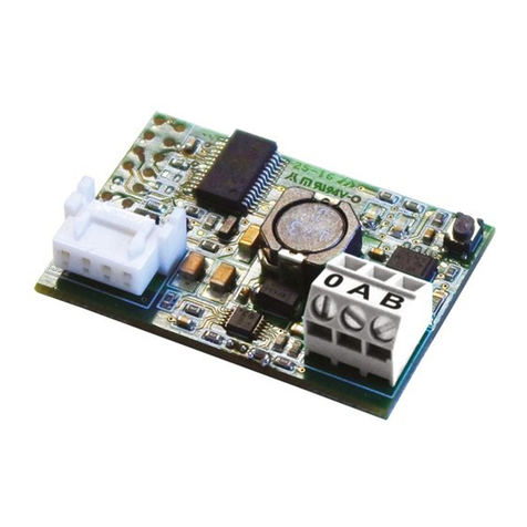
The B EBA WI-FI GATEWAY module allows you to connect a
supervisor*to the local network of compatible BFT U-link
devices by means of TCP/IP technology on the WI-FI Net-
work. The B EBA TCP/IP GATEWAY module must be con-
nected to the only local network device with the address 0.
Each network device must have a dierent address.
Using a U-link supervisor*, you can address each device in
the local U-link network and manage parameters, settings,
transmitters and diagnostics.
For information on the features of the supervisor and avail-
able functions, refer to the relevant manual.
The network is made up of a device with a B EBA WI-FI GATE-
WAY module to which all the other devices are connected
using twisted pair cabling in a U-link serial connection.
The smallest possible network is made up of a single device
with the address 0 with a B EBA WI-FI GATEWAY module.
Note: this board is compatible only with control panels us-
ing the U-link protocol.
(*) Supervisor means a handheld programmer or manage-
ment software.
See gures C and D for examples of installation.
3) TECHNICAL SPECIFICATIONS
Operating temperature -20°/+50° C
Max. connection distance with cable:
-B EBA WI-FI GATEWAY and B EBA RS 485 LINK
-B EBA RS 485 LINK and B EBA RS 485 LINK
250 m
Max. network length 500 m*1
Max Max. of devices on 485 network 32*2
B
EBA WI-FI GATEWAY band 2400-2483.5 MHz
Dimensions
42 x 29 mm (HxL)
Transmit Power +16dBm
Receiving Sensitivity -98dBm
Wi-Fi
- 802.11: b/g/n
- B
it rate: 72.2 Mbps
- Safety: OPEN,
WPA2/WPA
Personal and WEP
*1the max. network length can be extended using an RS
485 repeater.
*2the number of devices can be increased to 120 using an
RS 485 repeater.
4) WIRING REQUIRED FOR OPERATION (Fig.B)
The control panels are connected to each other with 3 wires
relating to the B EBA RS 485 LINK interface boards. Use twist-
ed pair cabling only. When using a telephone cable with
more than one pair, it is essential to use wires from the same
pair (A-B). The length of the cable between one module and
the next must not be greater than 250 m.
Terminal Description
RS485 A
RS485 B
RS485 0
Connection to the U-link network. Pay
attention to the polarity.
5) RESTORING FACTORY SETTINGS
Attention: it restores the factory pre-set settings.
-
PresswithoutreleasingtheRESETbutton(Fig.A)for5seconds.
-
AfterreleasingtheLED1button,theLED2ashesquicklyonce.
6) DIAGNOSTICS (Fig.A)
LED STATUS MEANING
LED 1 Fixed Led
Proper initialization and supply of
the module
LED 1 Led
ashing Faulty board
LED 2 Led access The LED detects the U-Link
connection to the board
7) INSTALLATION/CONFIGURATION
Warning:
- The images and screenshots used herein may dier from
the actual product.
After connecting the B EBA WI-FI GATEWAY to the device
in the proper terminal and have wired and congured the
U-Link network correctly. The B EBA WI-FI GATEWAY must be
congured in one of the following ways.
CONFIGURATION OF THE B EBA WI-FI GATEWAY
8) CASE 1: CONFIGURATION AS ACCESS POINT (FIG.C)
This type of connection allows you to manage a U-Link system with its own SSID (Name of the WLAN) by connecting directly
to the B EBA WI-FI GATEWAY of the wi from the PC, smartphone and/or tablet through the dedicated BFT software.
1.Connect the PC, smartphone and/or tablet to the SSID network identied by the name BeBa_Wi_<Mac address> (using
WPA2-PSK security type, and the default password BEBAWIFI) dened by the EBA B WI-FI GATEWAY. The Mac address of the
B EBA WI-FI GATEWAY is what is on the label on the B EBA WI-FI GATEWAY board.
The methods for connecting to the WiFi network vary depending on the PC, smartphone and/or tablet and operating
system adopted, to understand how to connect, check the instructions of the device.
2.After connecting to the B EBA WI-FI GATEWAY open the browser (be sure not to have the proxy server active), type in the
address bar the default address of 192.168.1.1 of the B EBA WI-FI GATEWAY.
It reaches the current conguration of the module page
Mode Operating mode set
SSID WLAN network name created by the WI-FI B EBA
GATEWAY [BeBa_Wi_<Mac address>]
BSSID MAC address
Channel Channel which transmits/receives the board
Security Security type set for the network operated by
B EBA WI-FI GATEWAY
6 - B EBA WI-FI GATEWAY B EBA WI-FI GATEWAY- 7

INSTALLATION MANUALINSTALLATION MANUAL
8.1) Step1: U-Link PARAMETERS SETTING
The B EBA WI-FI GATEWAY board to be used with dedicated BFT software needed to set the parameters for the U-Link by
clicking on the [U-Link] conguration in this installation menu.
Password AES Password for the AES encryption protocol U-Link.
Length between 8 and 16 characters. Bft12345 default value
Port: Port corresponding to the U-link service of the B EBA WI-FI
GATEWAY board. 1111 default value
After changing the parameters click [Save]
8.2) Step2: PARAMETER SETTING Access Point
In order to change the default access point, click [Access Point] in the installation menu.
Change the settings if necessary
SSID WLAN network name created by the WI-FI B EBA
GATEWAY [BeBa_Wi_<Mac address>]
Not modiable
Channel
Channel which transmits/receives the board
If multiple B EBA WI-FI GATEWAY are used in
proximity congured as an access point, reduce radio
interference by selecting dierent channels for each
of the adjacent B EBA WI-FI GATEWAY. A spacing of
four channels is recommended between the adjacent
B EBA WI-FI GATEWAY (for example, use channels 1
and 5, or 6 and 10).
Security
Security type set for the network operated by B EBA
WI-FI GATEWAY.
Possible settings:
-Open - Open network, without encryption
-WPA-PSK - Network encrypted according to WPA-
PSK Protocol
-WPA2-PSK - Network encrypted according to WPA2-
PSK Protocol
-
WEP - Network encrypted according to WEP Protocol
IP Address IP address assigned to the B EBA WI-FI GATEWAY
IP netmask Netmask setting
DHCP Enables/Disables DHCP of the DHCP server
DHCP start IP Address
Value of the rst address used by the DHCP server.
5 IP devices max.
To make the changes, click [Apply] , after this the board cannot be accessed with the default conguration.
Note: The data required in order to interface the B EBA WI-FI GATEWAY board with the BFT software is:
-IP of the board
-Port must answer the U-link service
-Password AES
9) CASE 2: CONFIGURATION AS CLIENT (FIG. D)
This type of connection allows to manage a U-Link system using the B EBA WI-FI GATEWAY board connected to an existing
WLAN network which is connected to the PC, smartphone and/or tablet always through dedicated BFT software.
1.Connect the PC, smartphone and/or tablet to the SSID network identied by the name BeBa_Wi_<Mac address> (using
WPA2-PSK security type, and the default password BEBAWIFI) dened by the EBA B WI-FI GATEWAY. The Mac address of the
B EBA WI-FI GATEWAY is what is on the label on the B EBA WI-FI GATEWAY board.
The methods for connecting to the WiFi network vary depending on the PC, smartphone and/or tablet and operating
system adopted, to understand how to connect, check the instructions of the device.
2.After connecting to the B EBA WI-FI GATEWAY open the browser (be sure not to have the proxy server active), type in the
address bar the default address 192.168.1.1 of the B EBA WI-FI GATEWAY
It reaches the current conguration of the module page
8 - B EBA WI-FI GATEWAY

ENGLISH
INSTALLATION MANUALINSTALLATION MANUAL
On the screen is shown:
Mode Operating mode set
SSID
WLAN network name created by the WI-FI B EBA GATEWAY [BeBa_Wi_<Mac
address>]
BSSID Mac address
Channel Channel which transmits/receives the board
Security Security type set for the network operated by B EBA WI-FI GATEWAY
9.1) Step1: U-Link PARAMETER SETTING
The B EBA WI-FI GATEWAY board to be used with dedicated BFT software needed to set the parameters for the U-Link by
clicking on the [U-Link] conguration in this installation menu.
Password AES Password for the AES encryption protocol U-Link.
Length between 8 and 16 characters. Bft12345 default value
Port: Port corresponding to the U-link service of the B EBA WI-FI GATEWAY
board. 1111 default value
After changing the parameters click [Save]
9.2) Step2: Client PARAMETER SETTING
In order to change the default setting of the B EBA WI-FI GATEWAY board to set it as a client click [Station] in the installation
menu.
Available
Networks Shows the list of networks that are visible and accessible from the module
SSID It indicates the wireless network to connect to. If the network is not visible
by setting [manual conguration] in [Available Networks] it is possible
to type the hidden wireless network name to which you want to connect.
Password Password of the WiFi network to connect to.
DHCP Enable it if is expected that the WLAN to which to connect automatically
associates the IP of the B EBA WI-FI GATEWAY
IP address Setting the IP address of the B EBA WI-FI GATEWAY board if DHCP is not
enabled.
IP netmask It sets the netmask of the B EBA WI-FI GATEWAY board if DHCP is not enabled.
IP gateway Setting the IP address of the router to which to connect if DHCP is not
enabled.
For the changes to take eect, click on [Apply]. After that the board is no longer accessible through the browser.
In order to restore the default conguration of the B EBA WI-FI GATEWAY board, see section RESET TO FACTORY SETTINGS.
Note: for correct operation with the BFT software the B EBA WI-FI GATEWAY board must be accessed with a xed IP and this
can be possible:
-setting it directly on the browser during client setup
-by setting a rule in the router that manages the WiFi network to which to connect that associates the Mac address of the
same IP board.
Note: The data required in order to interface the B EBA WI-FI GATEWAY board with the BFT software is:
-IP of the board
-Port must answer the U-link service
-Password AES
8 - B EBA WI-FI GATEWAY 9
www.BFTGateOpeners.com | (800) 878-7829 | [email protected]
Table of contents
Other BFT Gateway manuals