6 7
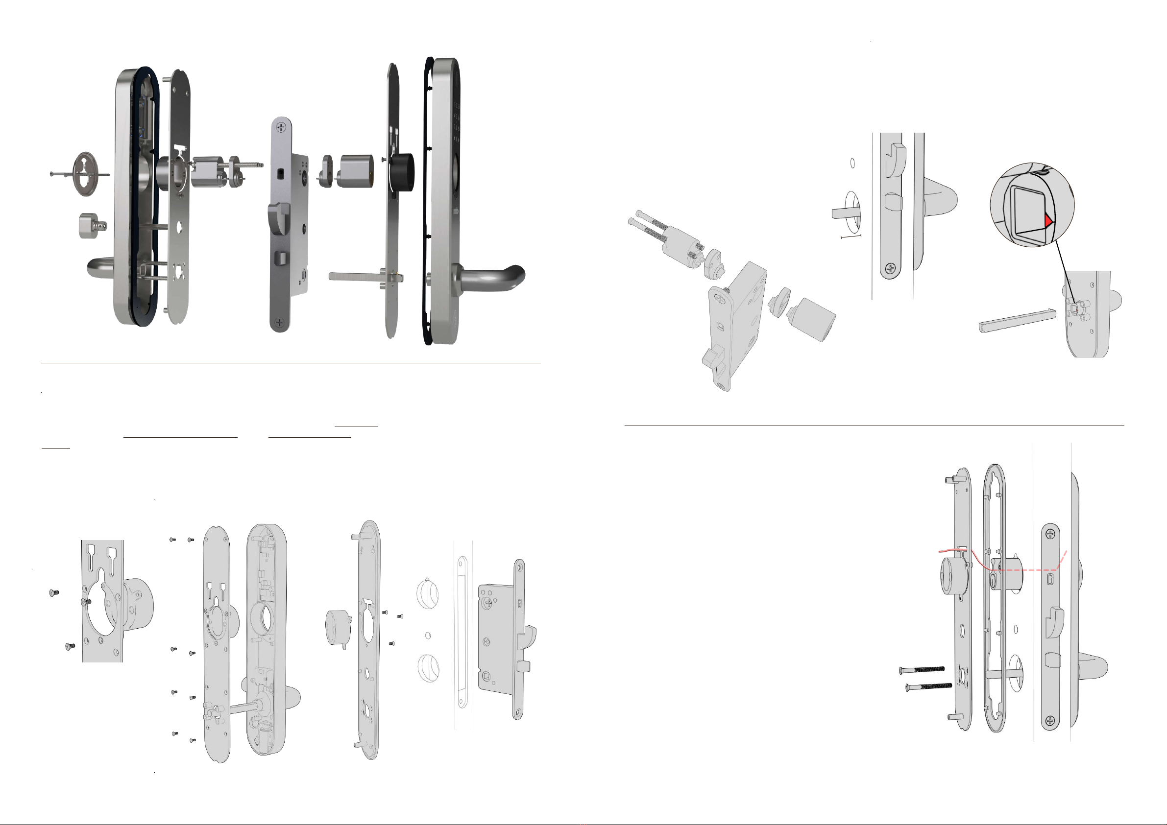
3.2.1 - Install lock box, cylinder and the square pin
3.2 Installation when round cylinder is used (oval, see 3.3) 3.2.2 - Use the inner part as a drill template
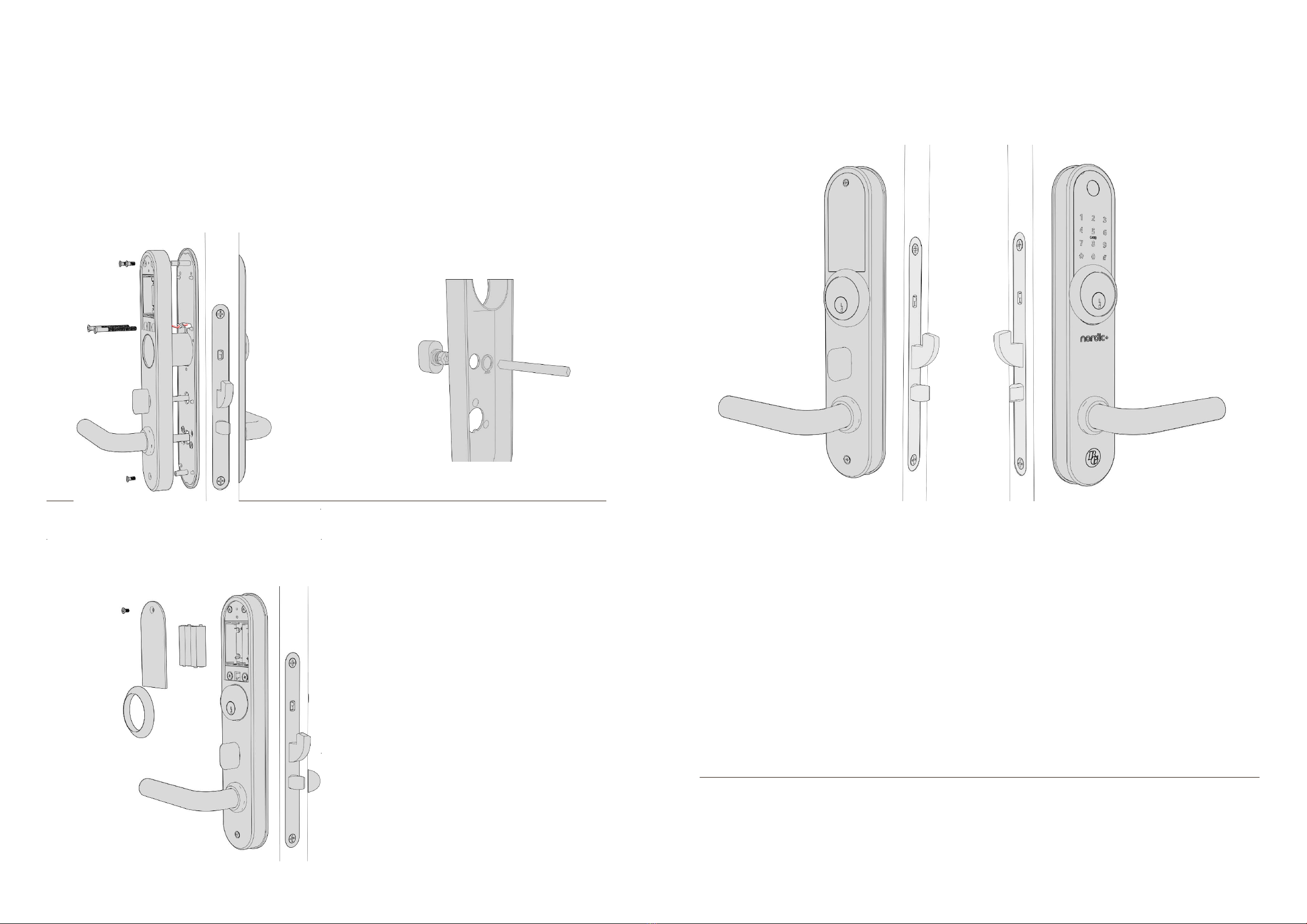
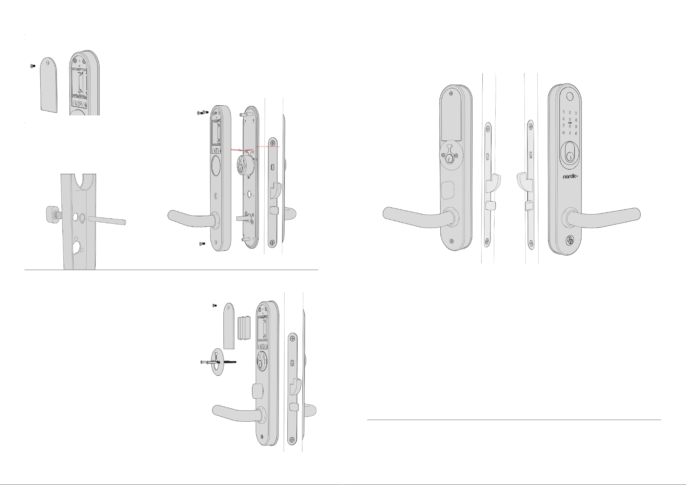
3.2.3 - Install inner plate with outer part.
Which of the 2
bottom holes should
be used depends on
the location of the
holes on the lock
box.
Adjust so that the
outer and inner part
sits horizontally and
screw the inner and -
the outer part with 2
x M5 waist screws
cut to the right length
from the inside.
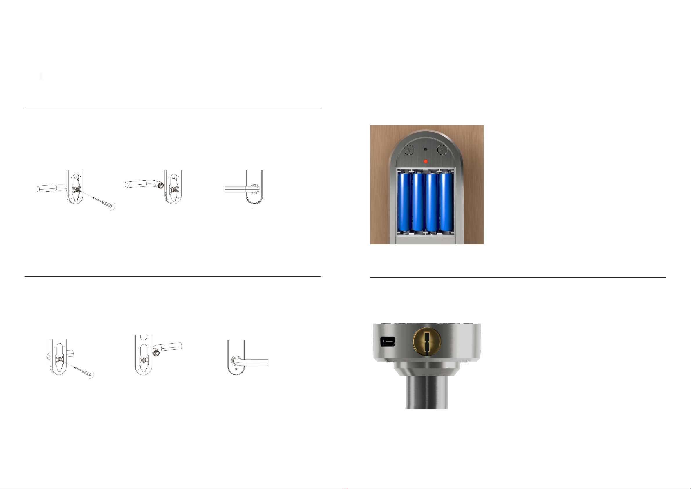
Unscrew the battery cover on the inner
part.
Choose a square pin and place in
the square hole of the lockbox.
Place the inner part over the square
pin and the lock cylinder. Hold the
square stick.
Make sure the lock ends up straight.
Mark the location of the two holes at
the bottom behind the battery door.
Use a sharp object and mark out the
center of the holes
Now do the same on the other
side of the door.
Use a 10 mm drill bit. Now drill
straight - about halfway from one
side and the rest from the other
side. This is to ensure nice drill
holes on the door.
Install the screw in the bushings. Hook the
bushings into the grooves on the back of the
outer part and press down into the bottom. Turn
the bushing to lock it into the bottom of the slot.
Fix the gasket.
The arrow where the square pin is mounted MUST point in
the opposite direction to the handle.
Place the outer part over the cylinder with the square pin
through the square hole. The bushings should now pass into
the 2 drilled holes. Be sure to bring the cable from the outer
part through the groove above the cylinder. Fix the gasket on
the sheet that belongs to the inner part. Place the plate over
the cylinder. The cable must exit through the groove on the
plate above the cylinder on the inner part.
File to make room for the cable with
connector above the cylinder on
both the inside and outside. Install
the locking box and screw. Feel
free to try that it is possible to pass
through the cable to the inside by
holding a cylinder in place.
Make sure cylinders with cylinder extenders
t in height. Strive to get the cylinder as
close in level with the outer or - the inner
part as possible unless cylinder rings are to
be used. Use screws of the appropriate
length and screw together.
If cylinder rings are to be used - t
cylinder extenders so that the correct
height is achieved.
Mount the cylinder sleeves.
Check that the length of the
square pin goes through the door
and about 20 mm into the inner
handle. The pin does not need to
be assembled. Cut if necessary.
Press the snap lock onto the
square pin and fasten to the outer
part. Make sure the snap lock
locks into the hole and the pin is
secured.
Make sure that the arrow
where the square pin is
mounted points in the
opposite direction to the
handle.