BHI NEDSP1061-KBD User manual

NEDSP1061-KBD Operating Manual
NEDSP1061-KBD Operating Manual Page 1
bhibhi
bhibhi
bhi
NEDSP1061-KBD
Noise Eliminating PCB Module
Installation
and
Operating Manual
Sound Engineering Solutions from bhi
1061-110D
Issue D
Complete with detailed fitting instructions for
Yaesu FT-817, Icom 706 MKII G
and Kenwood TS50
Page 36
bhibhi
bhibhi
bhi
Sound Engineering Solutions
DSP Noise Cancellation
bhi Ltd
22 Woolven Close
Burgess Hill
West Sussex
RH15 9RR
tel: +44 (0)845 217 9926
fax: +44 (0)845 217 9936
www.bhi-ltd.co.uk

NEDSP1061-KBD Operating Manual
Page 2
Important Information
Copyright
This publication, including all photographs and illustrations is
protectedunderinternationalcopyrightlaws,withallrightsreserved.
Neither this manual, nor any of the material within, may be copied
or reproduced without the written consent of bhi Ltd.
Disclaimer
Theinformationinthisdocumentissubjecttochangewithoutnotice.
bhi Ltd. makes no representations or warranties with respect to the
contents hereof and specifically disclaims any implied warranties of
merchantability or fitness for any particular purpose. Furthermore,
bhi Ltd. reserves the right to revise this publication and to make
changes from time to time in the content hereof without obligation
of bhi Ltd. to notify any person of such revision or changes.
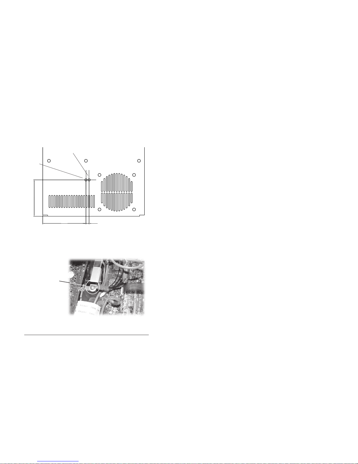
The fitting of the bhi NEDSP1061-KBD module may involve the
removal of small surface mount components and the drilling out of
the transceivers’case.This should only be carried out by a qualified
engineer. bhi accepts no responsibility for the fitting or installation
of the NEDSP1061-KBD module and are not liable for any damage
toequipmentcausedbyitsfitment.Fittingthis module may invalidate
your warranty.
All attempts have been made to ensure that this information is up to
date. It is possible that these instructions contain errors, or the
equipment is slightly different to the one used to compile this
information. In all cases it is up to the installer to ensure that the
module is fitted correctly.
By installing this module you are doing so at your own risk.
Page 35
Appendix D Other bhi products.Appendix D Other bhi products.
Appendix D Other bhi products.
NEIM1031 In-line module.
The NEIM1031 provides a flexible solution to noise reduction and
easily fits between your quipment and speaker.
Features:
•Fully adaptive noise cancellation 9 -35dB
•8 user selectable noise cancellation levels
•Mono earpiece socket
•Input sensitivity control
•Noise cancellation On/Off switch
•Line level in/out
•Input overload indication
•Power on/off with audio bypass.
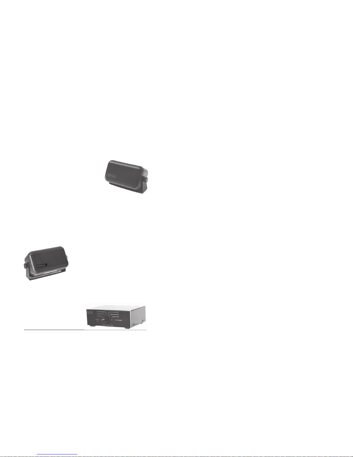
NEIM1031 accessories.
LSPKR
Quality 20 Watt extension
speaker for use with the
NEIM1031or any other audio
equipment. Fitted with a
3.5mm mono jack plug.
1031-STAND
Perspex mounting stand for the
NEIM1031.AllowstheNEIM1031
tobemountedforamore comfort-
ableoperatingposition.
NEDSP1062 - KBD: Amplified DSP module
controlled by a 2 button
keyboard.
1030-UKPA UK DC power adapter
1030-EUPA European DC power adapter
Easy to install retrofit for existing equipment and extension speak-
ers
NEDSP1062-PCB: Basic amplified DSP
module.
Amplified DSP modules.

NEDSP1061-KBD Operating Manual
NEDSP1061-KBD Operating Manual Page 3
Packing List:
Please check the contents of the box.
•Operating manual
•NEDSP1061-KBD assembly
•‘Z’ bracket
•Self adhesive mounting pads
•bhi NEDSP keyboard label
Toinstallthismodule you willneedthefollowing additional
items:
•service manual/circuit diagram of the equipment in
which the module is to be installed.
•all the appropriate tools to disassembling the
equipment
•suitable soldering iron and bits for working with
surface mount devices.
Before attempting to fit this module study this manual
thoroughly along with the service manual and
circuit diagramforyour equipment.Becarefulnot tomove
the wires on the module too much as this could lead to
damage.
Page 34
Appendix D Other bhi products.Appendix D Other bhi products.
Appendix D Other bhi products.
Appendix D
Other bhi products
bhi stock a comprehensive range of audio accessories and
adapters to suit most equipment, please call or visit www.bhi-
ltd.co.uk for more information. Full contact details on back page.
bhi DSP noise cancellation built into a
compact2.5Wattamplified speakerunit. the
unit provides an easy to install solution to
noise reduction and easily connects to the
extension speaker speaker socket or
headphonesocketofyourequipment.
Key features:
•Fully adaptive noise cancellation 9 -35dB
•8 user selectable noise cancellation levels
•Mono earpiece socket
•Input sensitivity control
•Noise cancellation On/Off switch
•LED indication of power and noise cancellation
•12-24VDCoperation
•On/Off audio bypass switch.
NES10-2 MKII Noise Eliminating speaker.
Basic plug and go noise cancelling
speaker preset to 20dB of noise
reduction. Easily connecst to the
extension speaker or headphone
socket on your equipment.
Key features:
•Fully adaptive noise cancellation 20dB
•12-24VDCoperation
NES5 Noise Eliminating speaker.
1042 switch box.
Allows up to 6 pieces of
equipment to be connected to
one speaker or inline module. 3
inputs loaded at 8 ohms.

NEDSP1061-KBD Operating Manual
Page 4
1. Introduction
1.1 NEDSP1061-KBD features 6
1.2 Limitations 6
1.3 Audio DSP noise cancellation 7
2. Module description
2.1 Module layout 8
2.2 Connections 8
2.3 Electrical characteristics 9
2.4 Controls 9
2.4.1 Input level 9
2.4.2 Output level 9
2.4.3 Beep volume level 9
2.4.4 Overload LED 9
2.5 Modulemounting 10
3. Installation 11
3.1 Introduction 11
3.2 Circuit location 11
3.3 Fitting 12
3.3.1 Audio connections 12
3.3.2 Powerconnections 13
4. Setup 14
5. Troubleshooting 15
6. Operation 16
6.1 Introduction 16
6.2 Operation 16
6.3 Demonstration mode 17
6.4 Notes about noise reduction 18
6.5 Noise reduction level 18
Contents
Page 33
The keyboard is retained using the supplied ‘Z’ bracket,
held in place by the loudspeaker clamp. Fix the dsp
module to the inside of the lid using the self adhesive
tape supplied.
Carefully replace the lid ensuring that none of the wires
are trapped.
Affix the bhi DSP label to the
lid, over the keyboard and
LED.
Figure 7. NEDSP1061-KBD module
mounting.
‘Z’ clamp
NEDSP1061-KBD
bhi DSP label
Appendix C Icom 706 MKII G

NEDSP1061-KBD Operating Manual
NEDSP1061-KBD Operating Manual Page 5
7. Machining drawings 19
Appendices
AppendixA
Yaesu FT-817 fitting instructions 20
Appendix B
Kenwood TS-50 fitting instructions 26
Appendix C
Icom 706 MKII G fitting instructions 30
Appendix D
Other bhi products 34
Page 32
Drill the keyboard holes in the case lid as shown in the
following diagram. Ensure the holes are de-burred.
Figure 5. Case lid machining diagram
Connect the black power lead from the NEDSP1061-
KBD module to the fan mounting screw, as shown in
figure 6.
Figure 6. 0V connection from the NEDSP1061-KBD
module.
NEDSP1061-KBD
0V
connection
Appendix C Icom 706 MKII G
5.1
70
59
4.0mm
3.5mm

NEDSP1061-KBD Operating Manual
Page 6
The NEDSP1061-KBD is a modular solution to noise
reduction. It incorporates DSP technology to provide up
to 35dB of noise cancellation. The module is controlled
by a single pushbutton with LED indication for ease of
use.
1.1 NEDSP1061-KBD module features:
•Fully adaptive to changing noise environments
•Input and output level controls
•Input overload indication
•Virtually no distortion to speech signal
•Up to 35dB of noise cancellation
•4or 8 levelsofnoisereduction selectable onpowerup
•5 – 15V supply range
•4.6dB on board gain
•Single key operation of all functions
•LED indication of DSP level and status
•Small size 26mm x 37mm
1.2 Limitations.
This module is designed to pass speech. Other signals
such as data and music will to some degree pass
through, but the integrity of these signals
cannot be guaranteed.
Thismoduleisdesigned to be placed in a low level audio
path only. The module will not drive a loudspeaker or
other high power load (see bhi NEDSP1062 amplified
DSP module).
The unit is single channel (mono).
1. Introduction.
1. Introduction.
Page 31
Cut the white wire clos-
est to the front of the
transceiver.
Connect the
NEDSP1061-KBD
screened lead as fol-
lows:
Red wire to connector
J1431
Blue wire to remaining
end of the cut lead.
Screen - cut off.
Figure 3. J1431 modified
connections.
The red power lead for
the NEDSP1061-KBD
is connected to the
PCB. Carefully remove
the solder mask from
the PCB surface in the
position shown in figure
4. (it may be necessary
to lengthen the lead).
Figure 4. PCB modification for power lead
;;
;;
yy
yy
Flat cable
J1381
C897
C1381
R1169 R1170
Remove solder
mask here
Connect Red
+Ve lead from
the NEDSP1061
here
Cut the white wire
Insulate both the connections with the supplied rubber
sleeves.
Appendix C Icom 706 MKII G

NEDSP1061-KBD Operating Manual
NEDSP1061-KBD Operating Manual Page 7
This module is designed for communication type
applications. The upper frequency limit is 4.5KHz and
therefore not suitable for hi fidelity applications.
1.3 Audio DSP Noise cancellation.
The bhi DSP processes the incoming audio signal and
then differentiates the speech from the noise. The
unwanted noise and interference is then attenuated to
leave only the speech.
The following diagrams are taken from actual audio
signals and illustrate how the audio signal is being
processed.
Figure 1. Noise cancellation.
Original signal.
Speech with a lot of
background noise
Processed speech.
Speech with reduced
noise
Speech Noise
Reduced noise
1. Introduction.
Page 30
Appendix C
Icom 706 MKII G
This document should be read in conjunction with the
relevant Icom 706 MKII G technical supplement.
Disconnect the power before commencing.
Figure 1. Loudspeaker
connector
Remove the 5 screws re-
taining the top cover.
Disconnect all the loud-
speaker connector.
Remove the lid.
The NEDSP1061-KBD
module is inserted into the
audio path on the 4 pin con-
nector J1431. This connec-
tor can be
located on the right hand side at the front of the main
board.
Audio connector
Figure 2. Location of
connector J1431
Appendix C Icom 706 MKII G

NEDSP1061-KBD Operating Manual
Page 8
2.1 Module Layout.
The following diagram shows the layout of the
NEDSP1061-KBD module.
Figure 2. Module layout.
2.2 Module Connections.
The NEDSP1061-KBD module has five connections.
Red wire: 5 - 15VDC
M3 Tag:0V
Screened Lead:Red Audio In (to module)
Blue Audio Out (from module)
Black Audio Screen
2. Module Description.
Output level
(P1) Input level
(P2)
Bi-colour
LED
Beep volume
(P3)
Red wire
(5-15VDC) M3 Ring Tag
(0V)
Overload LED
Push
button
Screened audio
lead
2. Module description.
Page 29
Figure 6. Switch mounting hole details.
Appendix B Kenwood TS50.
14. Solderthe screen fromtheDSPboard to theground
on CN10 and insulate with tape.
15. Refit CN10 plug into CN10 socket.
16. Replacethe speaker andspeakermountingbracket
making sure no wires are getting pinched.
17. Place two thicknesses of double sided tape to the
front right corner of the speaker bracket and mount
switch PCB (see figure 5).
18. Connect radio to power and aerial and test DSP
board works OK readjust beep, input and output
levels if required. (Details in section 4 page 14)
19. Drill the top cover as detailed below.
20. Place the cover on the radio and check alignment
of the switch and adjust if necessary.
21. Replace the top cover screws and fit the bhi label.
5.1
52.0
25.0
4mm
diameter
3.5mm
diameter
Front

NEDSP1061-KBD Operating Manual
NEDSP1061-KBD Operating Manual Page 9
2.3 Electrical characteristics.
scitsiretcarahClacirtcelE
retemaraP noitpircseD niM pyT xaM stinU
V
ni
egatlovylppuS5951V
I
ni
tnerrucylppuS5405Am
nIlangistupnioiduA05003smrV
tuO langistuptuooiduA )xamtupnisX7.1( 036smrV
Table 1. NEDSP1061-KBD Electrical characeristics
2.4 Controls.
Controls are provided to allow the NEDSP1061-KBD to
be integrated in to the target system. 3 level controls are
provided.
2.4.1 Input Level:
To set the audio level to the optimum level for the DSP.
2.4.2 Output Level:
To match the output level of the DSP module to that of
the following stage.
2.4.3 Beep volume level:
Allows the user to adjust the beep volume control to suit.
The beep volume can be reduced to zero if required.
The modules are factory set to the maximum level.
Turning the potentiometers anti clock wise will increase
the levels.
2. Module Description.
Page 28
10. Strip and tin the two ends of the clipped lead.
11. Remove some insulation from the CN10 ground
wire and tin.
12. Solder the red audio wire from the DSP board to
the lead coming out of the plug and insulate with
tape.
13. Solder the blue audio wire from the DSP board to
the remaining lead and insulate with tape.
Figure 5. Switch mounting detail.
Switch
Appendix B Kenwood TS50.
Figure 4. CN10 wiring detail.

NEDSP1061-KBD Operating Manual
Page 10
Note:
The potentiometers do not have end stops. It is possible
to set the potentiometer in a dead band between the
ends, resulting in the audio being lost, continue rotating
and the audio will return.
2.4.4 Overload LED.
The overload LED circuit monitors the amplitude of the
audio level entering the DSP module. The LED will
illuminate when the amplitude exceeds the maximum
permitted level. If the amplitude is increased further the
DSP will clamp the audio signal to prevent damage to
theDSPinput.Thiswill cause the audio signal to become
distorted. The optimum level is achieved when the
loudest peaks of the input audio, just cause the LED to
glow.
2.5 Module mounting.
The DSP module has four mounting holes that can be
usedtoretainthe unit inside the equipment.Alternatively
a self adhesive pad is supplied to allow the module to be
mounted in a convenient position - without the need for
drilling.
Two holes need to be drilled in the casing of the
equipment for the keyboard. Hole sizes and positions
can be found in section 7 - page 19.
Thekeyboardcanretainedusingthesupplied‘Z’bracket
oralternativelyretainedusingasuitableadhesive, or the
mounting pads supplied.
In some equipment it may be possible to clamp the
bracket under the loudspeaker bracket (e.g. FT-817)
Coverthekeyboard holes with the supplied self adhesive
label.
2. Module Description.
Page 27
7. Carefully scrape the solder mask off the track to
expose the copper.
8. Solder the red lead of the DSP board to this point.
9. Remove the plug from CN10 and clip the white wire
that is next to the ground in the middle.
Figure 3. Position of red wire.
Appendix B Kenwood TS50.
Figure 2. Location of earth point.
Earth Screw

NEDSP1061-KBD Operating Manual
NEDSP1061-KBD Operating Manual Page 11
Pre amp
NEDSP1061
Power amp
A
udio source Audio o
ut
3.1 Introduction.
Before commencing installation study the equipment’s
service manual/circuit diagram thoroughly to familiarise
yourself with the circuit diagram and disassembly
procedure. Detailed information for fitment into specific
equipment is available in the appendices of this manual.
Figure 3. Basic connection diagram
Figure 4. NEDSP1061-KBD Audio path
3. Installation
3. Installation.
Pre amp
NEDSP1061
Power amp
A
udio source Audio o
ut
Remove this
capacitor
Page 26
Appendix B Kenwood TS50.
Appendix B
Kenwood TS50
Have the front of radio facing you and refer to the
photographs in this manual to assist with the board
installation.
1. Remove the top cover from the radio.
2. Remove speaker and speaker mount.
3. Fix double sided tape to the bottom of the DSP
board (DSP chip side) making sure the tape lines
up with the edges of the board.
4. Fit the DSP board as shown in figure 1.
DSP module
C127
C126
CN10
Figure1. LocationofC126,C127,CN10 andDSPmodule
5. Remove the mounting screw for the fan and attach
the ground lug at this point.
6. Locate the pc board trace coming from pin 8 of the
audio amp chip (IC7) This track is between C127
electcapandC126elect surface mount cap.There
is a + printed on top of this track for C126 (see
figure 1).

NEDSP1061-KBD Operating Manual
Page 12
Pre amp
NEDSP1061
Power amp
Remove this
capacitor
Red
Blue
Screen
Fit the NEDSP1061-KBD
module in place of
the coupling capacitor
Loudspeak
er
Volume
For optimum performance provide the module with a
constantamplitude signal,forexamplebeforethe volume
control.
Figure 5. NEDSP1061-
KBD recommended
position.
Note:
On some modern receivers/transceivers the volume
control is digital and doesn’t operate in the audio path.
Contactthe manufacturer for advise for the mostsuitable
position for the DSP module..
3.3 Fitting.
After locating a suitable location for the module in the
circuit, refer to the service manual for disassembly
information.
3.3.1 Audio connections.
Carefully remove the chosen coupling capacitor, taking
care to not damage the PCB pads. Solder the blue wire
from the screened lead to the power amp side of the
capacitor and the red to the other.
The black wire should be connected to a convenient 0V
3. Installation.
Page 25
Appendix A Yaesu FT-817.
Figure 4. Keyboard mounting
Figure 5. Hole drilling detail
Keyboard mounting using the ‘Z’ bracket.
•Slacken the screws retaining the loudspeaker
•Position keyboard into the lid cutouts
•Place the ‘Z’ bracket over the keyboard, carefully
easing the bracket into position
•Retighten the loudspeaker bracket.
Loudspeaker bracket ‘Z’ bracket
Clamp ‘Z’ bracket
Front edge of lid

NEDSP1061-KBD Operating Manual
NEDSP1061-KBD Operating Manual Page 13
connection (this screens the cable and acts as a
mechanical fixing for the cable, protecting the capacitor
pads).
3.3.2 Power connections.
5 - 15VDC (9V typically) is required to operate the
module. The lower the voltage, the less heat the module
will have to dissipate.
Locate a convenient point to connect the power. Ensure
that this point is connected after the power switch,
otherwise the DSP module will be drawing power all the
time, and may discharge the batteries (where fitted).
Connect the red wire to this point.
The 0V connection is formed using the M3 ring tag.
Locatea suitable0Vpoint (such asaPCBretainingscrew
that is fixed into the chassis).
Whenrouting thewires,ensure they areawayfrom strong
sources of RF or high voltage.
3. Installation.
Page 24
Alternative location fixed to lid
(mount DSP up)
Screened lead
Keyboard assembly
M3 ring tag
Power lead
NEDSP1061 preferred
postition
(mount DSP down)
FT-817 speaker connector
Ensure these wires do not
foul the lid when fitted
Keep this area clear
for speaker
Appendix A Yaesu FT-817.
Figure 3. Fitted module

NEDSP1061-KBD Operating Manual
Page 14
The levels come factory set to the maximum position.
Thisshouldbe adequate for most applications. However
the module can be adjusted as follows.
Tune the equipment to a strong signal.
Switch off the noise reduction (LED will illuminate RED).
Adjust the input P2 until the overload led illuminates.
Back off the potentiometer approximately a 1/4 of a turn.
Adjust P1 to give the correct listening volume, without
distortion.
Adjust P3 to give the desired beep volume level, or off if
required.
4. Setup.
4. Setup
Page 23
The NEDSP1061-KBD screened lead fits in the cut out
provided for the front antenna connector.
Replace the main unit, connections, and all screws
except the front right hand screw.
Drill the holes for the lid, as per the drawing on page 25
of this manual.
The keyboard is mounted using the supplied ‘Z’ bracket.
See page 25 for more information on installing the
bracket.Alternativelyuse hot melt, epoxyor any suitable
adhesive affix the small keyboard to the inside of the lid.
Taking care to not get adhesive on the upper surface of
the lid, switch or LED.
Allow this to cure before continuing.
Appendix A Yaesu FT-817.
Replace the main unit PCB.
Solder the red (power) lead to the drain of Q1082
(TP1084).
ConnectM3 ringtag(0V leads)usingtheright frontscrew.
Affix the NEDSP1061-KBD module using the supplied
self adhesive pad in the chosen location.
The NEDSP1061-KBD can be
affixed in two positions.
The preferred position is in the
location of the optional filter. This
provides the more mechanically
securelocation.Iftheoptional filter
is(oris going to be) installed the module can beinstalled
on the inside of the lid (see photo).

NEDSP1061-KBD Operating Manual
NEDSP1061-KBD Operating Manual Page 15
Figure 6. Troubleshooting flowchart.
5. Troubleshooting.
5. Troubleshooting
Start
Audio
Distortion
Overload
LED
Illuminates Reduce input
level using P2
Reduce output
level using P1
Distortion
End
Yes
Yes
No
No
Page 22
Screen
Blue wire
Red wire
Figure 2.NEDSP1061-KBD connection detail
Q1084
Q1057
R1482
Lower side of main unit
Location of
C1338
on lower side
of main unit
Location of
Q1082 (TP1084)
on upper side of
main unit
Connect Red (+Ve wire)
to this point (see page
23)
Appendix A Yaesu FT-817.

NEDSP1061-KBD Operating Manual
Page 16
6.1 Introduction.
All functions of the NEDSP1061-KBD are controlled by
a single button.
•Single press turns the noise cancellation on/off.
•Holdingdownthe button changes the DSP filter
level.
The mode of operation is indicated both visually and
audibly.
The LED is illuminated red when the noise cancellation
is off.
When the noise cancellation level is changed the LED
willflashgreen to indicate which level has been selected.
Simultaneously the DSP will beep to give audible
indication of DSP level. This allows the operator to
change the DSP level without having to look at the LED
to see which level has been selected.
A short beep is emitted to acknowledge a button press.
The module will store the current DSP level, and will
return to this level when the equipment is switched on.
6.2 Operation.
Switch on the equipment.
The LED will illuminate red to indicate the noise
cancellation is off.The unit will flash/beep to indicate the
DSP filter level last used.
6. Operation
6. Operation.
Page 21
To place the module into the audio path it is necessary
to remove the audio signal coupling capacitor C1338.
The following diagram shows the position of the com-
ponent.
Carefully remove the capacitor.
Connect the screened lead from the NEDSP1061-KBD
module as follows:
•Red lead - to R1482 side of C1338 (audio in)
•Blue lead to the other side of C1338 (audio out)
•Screen to the grounded connection close to the
capacitor.
See figure 1 below for details.
NEDSP1061
Q1094
R1268
15K C1460
100p
R1482
1K C1338
100n
Remove
R1317
100K
R1459
10K
-
+To
Volum
e
contro
l
Red wire
Blue wire
Figure 1. Schematic detail. FT-817
Appendix A Yaesu FT-817.

NEDSP1061-KBD Operating Manual
NEDSP1061-KBD Operating Manual Page 17
Noise cancellation on/off.
Press and release the button and the LED will go green
indicatingthatthe noise cancellation is activated.Ashort
beepwillacknowledgethekeypress.
Changing the filter level.
Hold down the button. The led will flash the filter level,
and if the button is held it will step through all the levels,
audio beeps also indicating the filter level. When the
desired level has been reached release the button. This
newvaluewill be stored in the modules’ memory and will
bethe default setting the nexttimetheunit is powered up.
6.3. Demonstration mode.
The NEDSP1061-KBD module features 2 preset
demonstrationmodes,andtheabilitytoselect4or8filter
levels.Thesedemonstrate thenoise cancellationabilities
ofthe NEDSP1061-KBD module andthefilterlevel select
mode. To listen to the demonstration modes, or change
thenumber ofDSPlevels itisnecessary toputthe module
intothesetupmode:
6.3.1 Demonstration 1:
Holddownthebutton and switch on the equipment.After
a short time the unit will emit a 2 tone beep. Release the
button. The unit is now in demonstration mode 1.
The module will switch the noise cancellation on for 1.5
seconds, then off for 1.5 seconds. It will then move onto
the next level and repeat this continuously through all 4
levels.
This mode a particularly effective when the equipment
isjustreceivingstatic,asitdemonstratestheattenuation
of white noise at all the levels.
Alternatively tune the equipment into a good quality FM
speech broadcast. This demonstration shows how little
the DSP alters the speech, at any of the levels.
6. Operation.
Page 20
Appendix A Yaesu FT-817.
Appendix A
Yaesu FT-817
This document should be read in conjunction with the
relevant Yaesu FT-817 technical supplement.
The bhi NEDSP1061-KBD module is inserted into the
audiopath of thetransceiver, at a pointbeforethevolume
control. To access this point it is necessary to remove
the main unit.
Remove any fitted batteries or NiCad pack before
commencing installation.
Remove the top and bottom covers.
Remove the 5 main unit fixing screws.
Disconnect all connections - apart from the front unit
ribbon cable.
Hinge the main unit forward, over the front unit ribbon
cable.

NEDSP1061-KBD Operating Manual
Page 18
6.3.2 Demonstration 2:
Follow the procedure as above. Wait for the second 2
tone beep, then release the key.
In this mode the filter level is set to level 3.
The noise cancellation is switched on for 3 seconds, then
off for 3 seconds. This loops until the user aborts this mode.
This is a good demonstration for listening noisy SSB
conversations showing the before and after.
6.3.3 After the 3rd two tone beep the filter level pre-sets at
level 5 in 8 level mode, release the button to select this
mode. After the fourth 2 tone beep the module enters the
filter level select mode. 4 beeps will indicate 4 level mode
and 8 beeps 8 levels. Release the button after either the 4
or 8 beeps to select the desired level mode. The module
will return to normal operation after this, or hold down the
button until the 2 tone beep is heard. Release the button,
after a short delay the LED will flash indicating the stored
level, as during the normal switch on.
6.4 Notes about the noise reduction.
When using the module on level 4/4 or level 8/8 some
distortion may be heard. This is quite normal when listening
to high levels of noise at these levels.
6.5 Noise reduction levels.
6. Operation.
Page 19
Figure 7. Hole machining details.
7. Machining details.
7. Machining details
36.2
30.28
3.0
27.4
24.0
3.0
1.52
4 off holes
3mm diamet
er
DSP physical
dimensions
5.1
Keyboard
hole detail
4mm
diameter
3.5mm
diameter
Other manuals for NEDSP1061-KBD
1
Table of contents
Other BHI Control Unit manuals

BHI
BHI NEDSP1062 KBD User manual

BHI
BHI NEDSP1901-PCB User manual

BHI
BHI NEDSP1068-PCBA User manual

BHI
BHI NEDSP1061 User manual

BHI
BHI NEDSP1061-KBD User manual

BHI
BHI NEDSP1901-PCB-MIC User manual

BHI
BHI NEDSP1062 KBD User manual

BHI
BHI NEDSP1962-KBD Guide

BHI
BHI Compact In-line User manual

BHI
BHI NEDSP1061-PCB User manual
Popular Control Unit manuals by other brands

Boreal
Boreal WIFI2-B Installation, operating and servicing instruction

Campbell
Campbell CDM-A100 Series instruction manual

Gesint
Gesint LT quick start guide

Meyer Sound
Meyer Sound MDM-5000 SYSTEM COMPONENTS GUIDE

WifiTrax Model Science
WifiTrax Model Science WFD-46 operating manual

Electronics Diversified
Electronics Diversified Omega 2 user manual