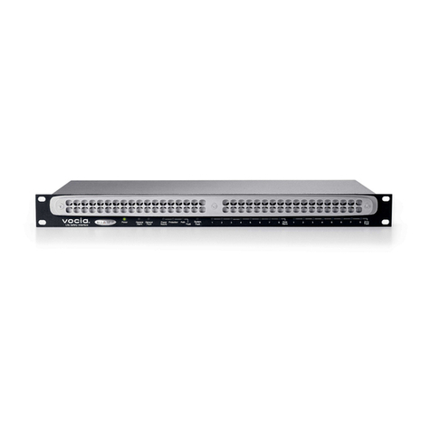
Biamp Vocia VI-8 User manual

Biamp Systems, 9300 SW Gemini Drive, Beaverton, Oregon 97008 U.S.A. (503) 641-7287 www.biamp.com
Vocia®
VI-8
Operation Manual
April 2014

2
TABLE OF CONTENTS
VOCIA 8-CHANNEL LIVE AUDIO INPUT DEVICE(VI-8). .............................4
FEATURES ..............................................................................4
SETUP AND USE ............................................................5
FRONT PANEL INFORMATION..............................................................5
Power (Chassis Indicator).................................................................5
Fault (Chassis Indicator)..................................................................5
Activity (Chassis Indicator) ................................................................6
Status (Chassis Indicator).................................................................6
Audio Channel .........................................................................6
REAR PANEL INFORMATION...............................................................7
Power ................................................................................7
Device ID .............................................................................7
Network...............................................................................8
Audio Inputs ...........................................................................8
Control Output Relay Connections ..........................................................8
Control Input Connections ................................................................9
Status Monitor Wiring ....................................................................9
VOCIA VI-8 SPECIFICATIONS.................................................10
WARRANTY ...............................................................11
COMPLIANCE .............................................................12
EC DECLARATION OF CONFORMITY ..........................................14
ROHS COMPLIANCE AND HAZARDOUS SUBSTANCE TABLE .....................15

3
IMPORTANT SAFETY INSTRUCTIONS
Lightning Bolt: Hazardous Live voltages present when this unit is in operation. Do not touch terminals marked with
this symbol while the unit is connected to live power.
Exclamation Point: Replace components (i.e. fuses) only with the values specied by the manufacturer. Failure to
do so will compromise safe operation of this unit
Hazardous Moving Fan Blades: Remove power before servicing and keep away from moving fan blades.
WARNING - To reduce the risk of re or electric shock, do not expose these products to rain or moisture. These products must
not be exposed to dripping or splashing and no objects lled with liquids, such as vases, shall be placed on these products.
WARNING – 100 Volt Speaker terminals marked with the symbol are Hazardous Live. External wiring connected to these
terminals requires installation by a Skilled or Instructed Person.
WARNING – MAINS Powered Products employ Safety Grounding and must be connected to a MAINS socket that is properly
grounded to provide a protective earthing connection.
Disconnect Device - The MAINS plug is used to disconnect MAINS power and must remain readily operable.
CAUTION – When POTS Telephone Interface options are provided, connections to the telecom circuits of this device must
be made by qualied, trained personnel. To reduce the risk of re, use only No. 26 AWG solid copper wire for telecom circuit
connections.
Intended for Installation and Service by Skilled Personnel Only:
CAUTION – To reduce the Risk of Electric Shock, Installation and Service of Biamp Products should be conducted only by
Skilled Persons who are Biamp Qualied Audio Installation Professionals.
Do not perform any servicing other than that contained in the Operating Instructions unless you are a Skilled Person qualied
to do so.
Skilled Persons must disconnect AC MAINS Power before opening product.
CAUTION - The Installation steps for ‘Auxiliary Power’ are for use by Skilled Personnel only and must comply with all local
codes.
• National Electrical Code, ANSI/NFPA 70 for United States.
• Canadian Electrical Code, Part 1, CSA C22.1, Sections 2-128, 12-010(3) and 12-100 for Canada.
Wall Mounting Instructions – Wall mounted products must be securely fastened to drywall or similar surface using a
minimum of 4 wood screws (2 screws for product with only two mounting holes). Alternate fasteners which may be used
include drywall anchors, self-tapping sheet metal screws located in metal studs or wood screws extending a minimum of ½
inch into wood studs.
Explanation of Graphical Symbols:
1) Read these instructions.
2) Keep these instructions.
3) Heed all warnings.
4) Follow all instructions.
5) Do not use this product near water.
6) Clean only with dry cloth.
7) Do not block ventilation openings. Install in
accordance with the manufacturer’s instructions.
8) Do not install near any heat sources such as
radiators, heat registers, stoves, or other products
(including ampliers) that produce heat.
9) Do not defeat the safety purpose of the grounding-
type plug. A grounding type plug has two blades and a
third grounding prong.
The third prong is provided for your safety. If the
provided plug does not t into your outlet, consult an
electrician for replacement of the obsolete outlet.
10) Protect the power cord from being walked on or
pinched, particularly at plugs, convenience receptacles
and the point where they exit from the product.
11) Only use attachments/accessories specied by the
manufacturer.
12) Use only with equipment rack,
cart, stand or table designed to provide
adequate mechanical strength, heat
dissipation and securement to the
building structure.
When a cart is used, use caution when moving the cart
and product combination to avoid injury from tip-over.
13) Unplug this product during lightning storms or when
unused for long periods of time.
14) Refer all servicing to qualied service personnel.
Servicing is required when the product has been
damaged in any way, such as power-supply cord or
plug is damaged, liquid has been spilled or objects have
fallen into the product, the product has been exposed to
rain or moisture, does not operate normally, or has been
dropped.

4
VOCIA 8-CHANNEL LIVE AUDIO INPUT DEVICE (VI-8)
The Vocia 8-Channel Live Audio Input Device (VI-8) is designed to facilitate the use of live audio Paging to Emergency and Non-emergency
Zones in a Vocia system. The VI-8 allows direct connection of up to eight analog mic/line audio inputs or digital CobraNet®audio connections
from external systems. Eight General Purpose Inputs and Outputs are provided and can be assigned to Control Events in the Vocia system.
The interface allows live, real-time audio Paging to any assignable Page Code or Zone within the Vocia World. The Status In and Status Out
allows for monitoring of multiple VI-8 devices and the Vocia emergency system.
The VI-8 supports Emergency Paging functions when a Vocia Life Safety Interface (LSI-16 or LSI-16e) is present in the system.
Features
• Eight analog mic/line or digital CobraNet audio inputs
• Device monitoring
• Four Control Outputs
• Eight Control Inputs
• Status monitoring through General Purpose Input and Output connections
• Power via 24V DC supply (dual inputs)
• Software-congurablesignalprocessingincludingvolumecontrol,lters,compressor/limiting
• CobraNet®audio and control over a single Ethernet cable
• Dual CobraNet Ports for redundancy
• Rotaryswitchesfordeviceidentication
• IP30 Compliant
• CE marked, UL listed and RoHS compliant
• Covered by Biamp Systems 5-year warranty

5
VOCIA 8-CHANNEL LIVE AUDIO INPUT DEVICE (VI-8) FRONT PANEL
Setup and Use
TheVociasoftwareprovidestheinterfaceforconguringandprogrammingtheVI-8.Theinformationsuppliedbythismanualrelatesto
hardware installation, physical connections, and device information. For more details on software setup, please consult the Vocia Software
Help File.
Front Panel Information
The VI-8 LEDs are as follows (from left to right when viewing the front of the chassis):
1. 24V DC power 1
2. 24V DC power 2
3. Fault
4. Activity
5. Status
6. Audio Channel 1
7. Audio Channel 2
8. Audio Channel 3
9. Audio Channel 4
10. Audio Channel 5
11. Audio Channel 6
12. Audio Channel 7
13. Audio Channel 8
Power (Chassis Indicator)
The VI-8 has two power indicators. If power is applied to one or both 24V DC power connectors, the corresponding LED will be on.
• Off – The power connection is not available or not within the voltage range.
• Solid green – The unit is receiving power.
Fault (Chassis Indicator)
There are two types of chassis Faults that will be reported depending on the severity of the problem. Audio may still be passing, but if the
condition causing the warning is not corrected, a failure may occur.
• Flashingamber–AControlInputconguredas“highrange–monitored”inputhasaFault.
• Solid amber – A chassis Fault is active on the VI-8.
Other manuals for Vocia VI-8
1
Table of contents
Other Biamp Recording Equipment manuals

Biamp
Biamp VOCIA LSI-16 User manual

Biamp
Biamp TesiraFORTE X User manual

Biamp
Biamp Crowd Mics Guide

Biamp
Biamp Tesira SERVER Guide

Biamp
Biamp Cambridge Qt 300 Operating instructions

Biamp
Biamp EQ301 User manual

Biamp
Biamp VOCIA VI-6 User manual

Biamp
Biamp VOCIA LSI-16 Manual

Biamp
Biamp SPM 412e User manual