Panduit smartzone 5-10KVA User manual

User Manual V3.2
UninterruptiblePower Supply
5-10KVA(SINGLE PHASE)
10-20KVA(3-PHASE)

SMARTZONEUPS USER MANUAL
1
Contents
Section 1 – System Overview....................................................................................3
Key Features ........................................................................................................4
Basic Operations...................................................................................................5
UPS Overview ...................................................................................................5
UPS Working Modes..........................................................................................5
UPS States........................................................................................................9
System Configuration Modes............................................................................12
UPS Physical Features and Accessories...............................................................15
Physical Features ............................................................................................15
UPS Accessories .............................................................................................24
Section 2 – Front Panel Display...............................................................................30
Status LED Indicators..........................................................................................30
Turning ON/OFF the UPS....................................................................................31
Starting the UPS on Main Input Power:..............................................................31
Cold Starting the UPS (Start the UPS on Battery):..............................................31
Starting a 3-Phase UPS with an Optional Maintenance Bypass Switch Unit: ........31
Switching to the Internal Bypass State:..............................................................31
Switching the 3-Phase UPS to the Maintenance Bypass state (with the optional
Maintenance Bypass Switch Unit - MBS):..........................................................32
Switching the 3-Phase UPS to Normal Mode from the Maintenance Bypass state
through the MBS..............................................................................................32
Shutting Down the UPS....................................................................................33
Display Operations..............................................................................................34
Menu Structure................................................................................................34
Display Icons...................................................................................................36
Initialization Page.............................................................................................38
Home Pages....................................................................................................39
Status Pages...................................................................................................41
Alarm Pages....................................................................................................48

SMARTZONEUPS USER MANUAL
2
Setup Pages....................................................................................................51
Maintenance Pages .........................................................................................70
Common Pages...............................................................................................75
About Pages....................................................................................................79
Appendix A1: 5 to 10kVA Fault Codes & Alert LEDs..................................................82
Appendix A2: 10 to 20kVA Fault Codes & Alert LEDs................................................89
Appendix B: Troubleshooting...................................................................................97
Appendix C: State Transitions Based on External Events .........................................99
Appendix D: Maintenance and Storage .................................................................101
Maintenance.....................................................................................................101
Storage/Transportation......................................................................................101
Appendix E: Configuration Options ........................................................................102
Appendix F: 10 to 20kVA Dry Contact Port Definitions and Assignments ..................108
Appendix G: 10 to 20kVA Back-feed Port Definition ................................................112
Appendix H: 10 to 20kVA REPO Port Definition......................................................113

SMARTZONEUPS USER MANUAL
3
Section 1 – System Overview
These Panduit SmartZone™ UPS units are true on-line double conversion systems that
deliver highly efficient and reliable power protection for your computer, IT,
communications, and automatic equipment. These units have high electrical
performance, intelligent monitoring, and network functionality to properly monitor and
condition the world’s power anomalies (power failures, power sags, power surges,
under-voltages, over-voltages, electrical line noises, frequency variations, switching
transients, and harmonic distortion).
Each UPS comes equipped with a color display and has multiple options for interfacing
with the unit. The UPS is standardly equipped with a network card for remote network
monitoring, control, and configuration. The UPS may be optionally ordered without a
network card. Additionally, a Network Card or a Dry Contact Relay Card may be
ordered as accessories.
These UPS units support VRLA (Valve Regulated Lead-acid) batteries as the backup
power storage system. The topology of these units is on-line double conversion with a
built-in economy (ECO) mode. The on-line double conversion architecture provides the
best power conditioning by recreating a true sinewave on the UPS outputs. The on-line
double conversion topology converts the input AC power to a DC power and then
regenerates the AC power on the UPS outputs. This double conversion allows the UPS
to eliminate the inconsistencies in the input power provided by the utility company. The
UPS may be optionally switched to ECO mode to increase the unit’s efficiency when the
input power is known to be stable (requires minimal conditioning).

SMARTZONEUPS USER MANUAL
4
Key Features
•Integrated data center solution – These UPS units integrate with multiple
External Battery Packs (EBP), offering an excellent choice for data center
deployment.
•Easy to Maintain – All UPS units support hot swappable battery cartridges.
•Easy to Maintain – These UPS units have an option to switch to bypass state.
•Easy to Maintain – All 3-Phase UPS units may integrate an external
Maintenance Bypass Switch (MBS), offering ease of maintenance while
maintaining power to the loads.
•Reliable - All UPS units are controlled by Digital Signal Processors (DSPs) which
increases reliability, performance, self-protection, and self-diagnostics.
•Intelligent Charging Method - The UPS units have an advanced three-stage
charging method to extend the batterylife and ensure fast charging.
o1st stage: constant current charging to quickly charge back to 90%
without over voltage.
o2nd-stage: constant voltage charging to make sure batteries are fully
charged with out over voltage.
o3rd stage: float voltage charging to ensure the battery stays charged to
the optimal level.
•Ease of Use - User Friendly Color Display with Color Status LEDs allow the user
to easily view UPS status and set operational parameters.
•Intelligent Monitoring Function – UPS units are standardly equipped with a
Network card for remotely controlling and monitoring the UPS via a user-friendly
Web Interface.
•Load Shedding – All UPS units that have outlets with one or two controllable
outlet groups may be used to shed non-critical loads while on batterybackup.
•Load Shedding - All UPS units with a network card have the capability to
gracefully shutdown smart loads.
•EPO Function - All UPS units are equipped with an Emergency Power Off
(EPO) interface to turn OFF the UPS output via a remote switch.
•Short circuit protection – All UPS units can protect against an output short
circuit. Note: Short circuit protection is available only when power is provided
through the inverter. The unit will be damaged if a short circuit occurs on the
output when the unit is providing power through the bypass power path.

SMARTZONEUPS USER MANUAL
5
Basic Operations
The basic operations of a double conversion UPS are explained through the high-level
generic block diagram in Figure 1. The generic diagram is only used for simple high-
level explanation of the UPS working modes and operating states. This block diagram is
not the actual block diagram of the UPS units.
UPS Overview
The input of the UPS is connected to an AC power source via an input plug or hardwire
connections. The output is connected to loads via outlets or hardwire connections on
the UPS. The load may be powered from the input source or the battery. The UPS
power switching circuitry may be isolated from the power chain while continuing to
power the load (ECO Mode or bypass state). The following UPS Mode and UPS State
sections use the simplified block diagram to help explain the modes and states of the
UPS.
Figure 1: High-level Generic Double Conversion UPS Block Diagram
UPS Working Modes
The UPS may be configured into four different working modes. This section provides an
explanation of these settable working modes. One of the four working modes are

SMARTZONEUPS USER MANUAL
6
manually configured into the UPS at setup time. The selected mode will become the
Default state of the UPS until the working mode is manually changed.
Normal Mode
Normal mode (on-line double conversion) is the default working mode of these UPS
units. When the UPS is set for Normal mode, it provides a stable pure sinusoidal AC
power output and charges or maintains the charge on the battery. In Normal mode, the
input and output relays are closed and the bypass relay is open. The rectifier/charger
derives power from the AC Input and supplies DC power to the inverter while
simultaneously charging or maintaining the charge on the battery. The inverter inverts
the DC power to AC power and supplies it to the load with a stable pure sinusoidal AC
voltage and current waveform.
When the UPS is operating in Normal mode, if the input power is lost or has any other
anomalies that are outside of the set ranges:
•The batteries will stop charging (input relay will open)
•The bypass relay will remain opened
•The output relay will remain closed
•The battery will start providing the DC power to the DC to AC inverter, continuing
to provide uninterrupted AC power to the load.
The UPS is now in the Battery state and will indicate an alarm. The UPS will continue to
provide power to the load for a limited time (runtime of the battery backup system
connected to the UPS for the percentage of load connected).
If an internal or an external output event occurs while operating in Normal mode:
•The input relay may open (depending on the internal event)
•the output relay will open
•The bypass relay will close (assuming the input is not outside of the input bypass
range), continuing to provide minimally conditioned AC power to the load.
The UPS is now in the Bypass state and will indicate an alarm. Refer to Appendix C:
State Transitions Based on External Events.
Note: This unit does have short-circuitprotectionbut only when power is being provided to the
load through the inverter.If the unit is in ECO mode or in the bypass state when a short-circuit
occurs on the output of the UPS, the UPS unit may be damaged.

SMARTZONEUPS USER MANUAL
7
ECO Mode
When the UPS is in Normal mode and the power requirements for the load are not
critical and the input source is stable (no power anomalies), the UPS may be set to
Energy Savings (ECO) mode to increase the efficiency of the power supplied through
the UPS. In ECO mode, all voltage increases and decreases will be passed along to the
load. Additionally, any frequency variations on the input will get passed on to the load.
When the UPS is manually configured for ECO mode, the output relay opens, and the
bypass relay closes. The input relay remains closed, continuing to keep the backup
batteries charged. When the UPS is in ECO mode the source power is minimally
conditioned.
If the input power is lost while the UPS is operating in ECO mode:
•The batteries will stop charging (input relay will open)
•The bypass relay will open
•The output relay will close
•The battery will start providing the DC power to the DC to AC inverter, continuing
to provide uninterrupted AC power to the load.
The UPS is now in the Battery state.
While the UPS is operating in ECO mode, if the input power has any other anomaly
(power sags, power surges, under-voltages, over-voltages, electrical line noises,
frequency variations, switching transients, and harmonic distortion) that is outside of the
bypass set ranges:
•The input relay will remain closed (continuing to charge the battery– assume the
anomaly is still within the operating range of the UPS)
•The bypass relay will open
•The output relay will close
•The rectifier will start providing the DC power to the DC to AC inverter, continuing
to provide uninterrupted AC power to the load.
The UPS is now in the Normal state. Ifthe anomaly is outside of the UPS operating
range, then the UPS will transition to the Battery state. Refer to Appendix C: State
Transitions Based on External Events.
If an internal or an external output event occurs while operating in ECO mode, the
bypass relays will open, the input relay will open, and the output will shut down. AC
power to the load will be lost.
SMARTZONEUPS USER MANUAL
8
Note: This unit does have short-circuitprotectionbut only when power is being provided to the
load through the inverter.If the unit is in ECO mode or in the bypass state when a short-circuit
occurs on the output of the UPS, the UPS unit may be damaged.
Convert Frequency (CF) Mode
The UPS may be set to Convert Frequency (CF) mode to increase the allowable input
frequency range of the UPS while maintaining the desired output frequency. Setting the
UPS to CF mode may require the UPS unit to be derated. The 5-10kVA UPS units in CF
mode are derated to 80% of the maximum output but will maintain a 50Hz output
frequency with an input frequency from 46Hz to 54Hz or a 60Hz output frequency with
an input frequency from 56Hz to 64Hz. The 10-20kVA 3-phase UPS units in CF mode
have no derating and will maintain a 50Hz or 60Hz output frequency with an input
frequency from 46Hz to 64Hz. When CF mode is set, the Bypass state is automatically
disabled (the unit cannot switch to the Bypass state under any conditions, frequency
conversion is not supported through the bypass path).
While the UPS is operating in CF mode, if the input power is lost or has any other
anomalies that are outside of the set ranges:
•The batteries will stop charging (input relay will open)
•The bypass relay will remain opened
•The output relay will remain closed and the batterywill start providing the DC
power to the DC to AC inverter, continuing to provide uninterrupted AC power to
the load.
The UPS is now in the Battery state. The UPS will continue to provide power to the load
for a limited time (runtime of the batterybackup system connected to the UPS for the
percentage of load connected).
If an internal or an external output event occurs while operating in CF mode, the output
relay will open and the output will shut down. AC power to the load will be lost. Refer to
Appendix C: State Transitions Based on External Events.
Generator Mode
The UPS may be set to Generator mode to enable the UPS to have a wider input
frequency range (40Hz to 70Hz). Setting the UPS to Generator mode may require the
UPS unit to be derated. The 5-10kVA single-phase UPS units in Generator mode are
derated to 75% of the maximum output but will maintain a 50Hz or 60Hz output
frequency over the full input frequency range. The 10-20kVA 3-phase UPS units do not
have a Generator mode setting. These units always operate with a wider input

SMARTZONEUPS USER MANUAL
9
frequency range with no derating.
Note: The Generator mode is saved on the 5-10kVA UPS units; when the 5-10kVA UPS unit is
powered OFF and restarted,the unit will restartin Generator mode.
While the UPS is operating in Generator mode, if the input power is lost or has any
other anomalies that are outside of the operating range of the UPS,
•The batteries will stop charging (input relay will open)
•The bypass relay will remain opened
•The output relay will remain closed and the batterywill start providing the DC
power to the DC to AC inverter, continuing to provide uninterrupted AC power to
the load.
The UPS is now in the Battery state. The UPS will continue to provide power to the load
for a limited time (runtime of the batterybackup system connected to the UPS for the
percentage of load connected).
If an internal or an external output event occurs while operating in Generatormode, the
input and output relays open and the bypass relay closes (assuming the input is not
outside of the input bypass range), continuing to provide unconditioned AC power to the
load. The UPS is now in the Bypass state with no frequency or voltage conditioning.
Output frequency and voltage will equal input frequency and voltage. Refer to
Appendix C: State Transitions Based on External Events.
Note: The UPS does not have output short circuitprotectionin the Bypass state.
UPS States
The UPS automatically transitions to different statesbased on internal or external
events; the user may also force the UPS into some statesthrough one of the user
interfaces. There are eight different states that the UPS may be in. Refer to Appendix
C: State Transitions Based on External Events .
Normal State
The UPS will go into the normal statewhen the UPS is set to Normal Mode at setup
time. This is the default mode and state that the UPS will power up in on new units from
the factory. If the UPS is set for Normal Mode, the Normal state is the default state
where the UPS will return to after the internal or external event has been cleared or the
forced state has expired.

SMARTZONEUPS USER MANUAL
10
If an internal or external event occurs while operating in the normal state, the UPS will
automatically transition to battery, bypass, fault, or battery test state depending on the
event.
ECO State
The UPS will go into the ECO state when the UPS is set to ECO Mode at setup time. If
the UPS is set for ECO Mode, the ECO state is the default state where the UPS will
return to after the internal or external event has been cleared or the forced state has
expired.
If an internal or external event occurs while operating in the ECO state, the UPS will
automatically transition to normal, battery, fault, or battery test state depending on the
event.
CF State
The UPS will go into CF state when the UPS is set to CF Mode at setup time. If the UPS
is set for CF Mode, the CF state is the default state where the UPS will return to after
the internal or external event has been cleared or the forced state has expired.
If an internal or external event occurs while operating in the CF state, the UPS will
automatically transition to battery, bypass, fault, or battery test state depending on the
event.
Gen State
The UPS will go into Gen state when the UPS is set to Generator Mode at setup time. If
the UPS is set for Generator Mode, the Gen state is where the UPS will returnto after
the internal or external event has been cleared or the forced state has expired.
If an internal or external event occurs while operating in the Gen state, the UPS will
automatically transition to battery, bypass, fault, or battery test state depending on the
event.
Battery State
The UPS automatically transitions to the Battery state with no power interruption to the
load when input power is out of the set range or power is lost. The UPS will
automatically return to the default state when the input source recovers.
If an internal or external output event occurs while operating in the Battery state, the
output will shut down. AC power to the load will be lost.
Bypass State
The UPS may automatically transition to the Bypass statewith no power interruption

SMARTZONEUPS USER MANUAL
11
when an internal or an external output event occurs (depending on the event). The UPS
may also be set to the Bypass state by turning OFF the invertor, but the input voltage
and frequency must be within the specified upper and lower limits of the bypass as
specified during the UPS setup. For the 5-20kVA UPS units, turn ON/OFF the inverter
through the Common Menu page. While the UPS is in the Bypass state, the source
power is minimally conditioned. Most variations in frequency and voltage will get passed
on to the load.
If an internal or an external output event occurs while operating in the Bypass state, the
UPS will transition to the Fault state and the output will shut down, AC power to the load
will be lost.
Maintenance Bypass State
Maintenance Bypass state is supported on the 3-Phase UPS units only. Manual
intervention is required to transition into and out of this state.This state also requires a
Maintenance Bypass Switch (MBS) unit, sold as a UPS accessory. The UPS may be
switched into the Maintenance Bypass state, through a sequence of switches on the
MBS unit, to perform periodic maintenance on the UPS. The MBS unit will electrically
disconnect the UPS from the system. In the Maintenance Bypass state, the source
power is provided to the load with no power conditioning. All UPS maintenance should
be performedin off hours by qualified personnel only.
If input power is lost while operating in the Maintenance Bypass state, AC power to the
load will be lost.
Refer to the Maintenance Bypass Switch (UMB20K)section in this document.
Fault State
The UPS automatically transitions into the fault state when the UPS is unable to provide
power to the load. The input, output, and bypass relays will all open. If the fault clears,
the UPS should transition back to the Default state (depending on the fault that is
cleared).
Battery Test State (Self-Check State)
The UPS may be manually or automatically put into the Battery Test state (sometimes
referred to as the Self-Check State), but the UPS will automatically transition back to the
Default state when the test is complete. The battery test will automatically run when the
UPS is powered ON and periodically while the unit is operating. The batterytest may
also be manually executed at any time. The frequency and duration of the batterytest
may have an impact on the batterylife. All batterytests are preset for a duration of 10

SMARTZONEUPS USER MANUAL
12
seconds. The frequency of the test is user selectable. For the 5-20kVA UPS units, the
battery test may be automated through the network card or scheduled through the
Maintenance Menu on the UPS Display.
Note: If automaticbatterytesting is setup through the Network Card, then automaticbattery
testingshould be disabled through the MaintenanceMenu on the UPS Display. If automatic
battery testingis setup through the MaintenanceMenu on the UPS Display, then automatic
battery testingshould be disabled in the Network Card.
When the battery test runs, the battery discharges for 10 seconds through both the
externally connected load and internal load.
Note: If a batterytest is run just after the UPS was running in the batterystate,it may produce a
Battery low (EOD) alarm and/or a Battery Self-Testerror because the battery was too low when
the test was started. This does not mean your battery is defectiveor at end of life. Try rerunning
the battery test afterthe batteryhas been fullycharged. If Batterylow (EOD) alarm is already
present when the battery test is initiated,the UPS will not start the battery test.
System Configuration Modes
Only the 10-20kVA 3-phase UPS units allow the user to change the system
configuration. The system configuration allows the UPS to be connected into a larger
system. By default, all UPS units are configured to be their own independent system.
Single Mode
By default, all UPS units are configured and wired as a single mode system. A single
mode system is a single UPS (and EBP unit(s))connected to an AC power source, and
that UPS provides the AC power to the load(s).
Parallel Mode
All 10-20kVA 3-phase UPS units may optionally be configured and wired as a Parallel
mode system. A Parallel mode system allows two to four UPS units of the same rating
to be connected in parallel. The Parallel mode system allows the group of UPS units to
behave as one large UPS system and/or as a system with redundancy. (Redundant
units are not calculated in the overall capacity of the parallel system).
Note: There are criticalrestrictionsfor connecting these units in parallel.

SMARTZONEUPS USER MANUAL
13
Figure 2: Parallel System Power/Control Connections
Parallel Mode System Restrictions
To ensure that all UPS units in the Parallel mode system configuration are equally
utilized and comply with relevant wiring rules, the following restrictions must be met:
•All UPS units must be of the same rating.
•The input main of all the UPS units must be connected to a common input bus.
•The input bypass of all the UPS units must be connected to a common input bus.
•The output of all the UPS units must be connected to a common output bus.
•The length and specification of all UPS power cables (main input, bypass input,
and the output cables) must be the same type and same length. This helps to
facilitate load sharing and zero crossing alignment between the UPS units when
operating in Parallel Mode.
Parallel Mode Setup and Startup
Each UPS unit in the Parallel mode system must be properly configured before the
outputs of the Parallel mode system are connected.
•Confirm that all breakers in the Parallel Mode system are open.
•Confirm that the input power connections and the input phase sequence is
correctly connected. Leave outputs disconnected.
•Confirm that the +/- battery voltage of all EBP groups are correct.
•Confirm that the parallel control cables are connected in a ring configuration
between all UPS units in the Parallel mode system (refer to the control
connections in Figure 2).
•All parallel mode system setting must be completed on each unit before the
outputs are connected.

SMARTZONEUPS USER MANUAL
14
•With the outputs disconnected, power ONall UPS units. On the first unit, set the
System Configuration mode to Parallel, set the working mode to Normal, and set
the Parallel IDto 1. Then set the number of parallel UPS units (Parallel Basic
Units) to the number of units that will be in the system (2-4). Then set the number
of the redundant UPS units (Parallel Redundancy Units) to the number of
redundant units in the system, if redundancy is desired in the system (0-3, no
redundancy = 0).
Note: Redundant units are not calculatedin the overall capacityof the parallelsystem.
•Follow the configuration steps above to setup the second UPS unit in the Parallel
mode system. This unit should have all the same settings except the Parallel ID
on this UPS unit should be 2.
•Make these configuration settings for the rest of the UPS units in the Parallel
mode system; making sure the Parallel ID is unique for each UPS unit in the
Parallel mode system.
•After all UPS units in the Parallel mode system are configured, power OFF all the
UPS units in the system. Connect the outputs of all the UPS units in the Parallel
mode system together and to the load.
•Power ON all the UPS units in the Parallel mode system.
•Then turn ON all battery breakers and confirm the parameters(V/I) are normal.
•Toggle the utility breaker OFF and ON to confirm that all the UPS units in the
Parallel mode system transition from the Default state to the Battery state and
then back to Default state.
•To operate the Parallel mode system in ECO mode, find the master unit (check
the Status Infopage of each unit in the system for the Master unit – this will
typically be the unit with the Parallel ID set to 1) and change the working mode
on this unit to ECO mode. This will change all the UPS units in the Parallel mode
system to ECO mode. To change back to Normal mode, change the working
mode on the master unit back to Normal mode, then all the units in the Parallel
mode system will change back to Normal mode.

SMARTZONEUPS USER MANUAL
15
UPS Physical Featuresand Accessories
The following sections provide an overview of the human and electrical interfaces on the
UPS unit. All UPS units are rack mountable with a display on the front side of the unit.
Physical Features
UPS Front Panel
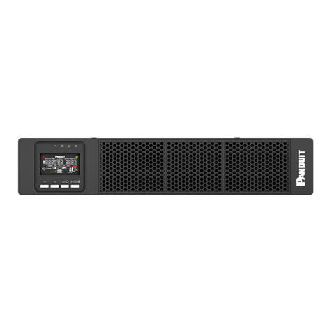
The UPS Front Panel for all 5-10kVA 1-Phase and 10-20kVA 3-Phase Models are the
same. Air flow vents occupy about ¾ of the front panel and a display module occupies
the right ¼ of the front panel. The front panel contains four Status LEDs, a 3.5-inch
color touch screen display and a power ON button.
Figure 3: 5 to 20kVA Front Panel
Air Flow Vents
The air flow vents are very critical to the operation of the UPS unit. These vents must
remain clean and clear of all objects that may restrict the air flow through the UPS unit.
Status LEDs
Each unit has four Status LEDs, Normal LED (green), Battery LED (yellow), Bypass
LED (blue), and Alert LED (Red or Yellow). These LEDs provide a quick high-level view
of the units operating conditions. Refer to Front Panel Display section for further details.
Color Display
The unit has a 3.5-inch touch screen color display. This display is used for monitoring,
controlling, and configuring the UPS. The display should automatically adjust to the
orientation of the unit. To lock the proper orientation, manually configure the setting in
the screen setup page on the display.

SMARTZONEUPS USER MANUAL
16
Power ON Button
The UPS has a single push button switch to the right of the display. This push button
switch is used to cold start the UPS.
UPS Rear Panel
The rear panel varies based on the UPS unit model. Refer to the UPS Physical Feature
call out tables and the Model specific figures in the section for details.
Intelligent Slot (INTELLIGENT SLOT)
Each UPS unit is standardly equipped with a Network management Card. Alternatively,
the UPS may be ordered with an empty Intelligent Slot, and later updated with a UPS
Network Management Card or a UPS Relay Card.
EPO/REPO Signal Port (EPO/REPO)
The 5-10kVA single-phase UPS units come equipped with an Emergency Power Off
signal port, labeled EPO. These UPS units come equipped with a 2-pin plug wired to
provide a short that results in normal UPS operation.
CAUTION: If the plug or shorting wire is removed, the UPS system will be
commanded to shut down. In typical applications, the plug will be wired to a remote
normally closed dry contact to provide a short for normal operation. The remote dry
contact could be opened to command the UPS to shut down in an emergency.
The 10-20kVA 3-phase UPS units come equipped with a Remote Emergency Power Off
signal port, labeled REPO. These UPS units come equipped with a 4-pin plug wired to
provide a short on pins 3 and 4 that results in normal UPS operation. This plug could be
wired for a remote normally open REPO device or for a remote normally closed REPO
device.
CAUTION: If the plug or default shorting wire is removed, the UPS system will be
commanded to shut down. In typical applications, the plug will be wired to a remote
normally closed dry contact to pins 3 and 4, to provide a short for normal operation or
wired for a remote normally opened dry contact to pins 1 and 2 (requires shorting wire
between pins 3 and 4). A remote normally open or normally closed dry contact could be
used to command the UPS to shut down in an emergency. Refer to Appendix H: 10 to
20kVA REPO Port Definition for details.
DB9 Coms Port (RS232)
All units have a DB9 equipped with an RS232 serial communications port. This serial

SMARTZONEUPS USER MANUAL
17
port is used for UPS core Firmware Updates.
USB Coms Port (USB)
All units include a USB serial communications port. This communication port is reserved
for “Future Use”.
Input Power Cord (INPUT)
Each UPS Model may have a unique power input connector, labeled INPUT. Refer to
the corresponding Product Specification Sheet for detailed definition.
Chassis Ground Connection Point ( )
All units have a chassis ground connection, labeled with a ground symbol. This is used
to ground the UPS and EBP chassis to the rack/cabinet. For safety and proper
grounding procedures, this grounding connection point must be connected to the
rack/cabinet ground.
Output Receptacles (GROUP1, GROUP2, GROUP3)
Each UPS Model has unique groups of power output connectors, labeled GROUP 1 and
GROUP 2. Some UPS Models may also have a GROUP 3 outlet group. The following
sections define typical output receptacles. Refer to the corresponding Product
Specification Sheet for latest detailed definition.
EBP Connector (BATTERY CONNECTOR)
All units have an External Battery Pack (EBP) power connection to connect to an
external batterypack labeled ±120Vdc or ±240Vdc. Each UPS Model has been
calibrated to a specific EBP and EBP Operating Voltage. The EBP units are not
interchangeable due to the operating voltage. The 5-10kVA single-phase UPS units
utilize the 240Vdc (±120Vdc) EBP. The 10-20KVA 3-phase UPS units utilize the 480Vdc
(±240Vdc) EBP.
Maintenance Bypass Signal Port (MAINT.)
All units have a Maintenance Bypass Signal port, labeled MAINT. This port is used to
detect if the external Maintenance Bypass Switch breaker (P/N UMB20K) is in the
opened or closed position/status. The opened position means that utility power is
switched to be fed to the input of the UPS. The closed position means that all power has
been removed from the UPS so it can be removed from the system to perform periodic
maintenance. The external Maintenance Bypass Switch is only supported on the 10-
20kVA 3-Phase UPS platform. This port should be unconnected on all 5-10kVA single-
phase UPS units. This port should be unconnected on all 10-20kVA 3-phase UPS units
when no external MBS is present in the system and should be connected to the MAINT

SMARTZONEUPS USER MANUAL
18
port on the MBS unit when the MBS unit is present in the system.
Note: The MBS is not supported in a Parallel mode system.
Parallel Ports (PARALLEL 1, PARALLEL 2)
All 10-20kVA 3-Phase UPS units have two (DB15) parallel port connections (one male
and one female). These connections are used to wire the communications for two to
four UPS units of the same rating in Parallel mode system.
Dry Contacts (IN 1-8, OUT 1-8)
All 10-20kVA 3-Phase UPS units have four input and four output dry contact ports.Each
dry contact port is across two dry contact connections (1 and 2, 3 and 4, 5 and 6, 7 and
8). These dry contact ports allow remote control (IN) and monitoring (OUT). These
contacts are provisioned in the dry contact setup pages in Section 2 – Front Panel
Display of this document.
Output Sensor Port (OUTPUT)
All 10-20kVA 3-Phase UPS units have an output sensor port. This port is used to detect
the status of the external Maintenance Bypass Switch (P/N UMB20K) Output Breaker.
This port should be unconnected when no external Maintenance Bypass Switch is
present in the system and should be connected to the OUTPUT port on the MBS unit
when the MBS unit is present in the system.
RJ45 Port (RS485)
All 10-20kVA 3-Phase UPS units have an RS485 serial communications port. This
communication port is reserved for “Future Use”.
Back-Feed Contacts (BACKFEED 1-4)
All 10-20kVA 3-Phase UPS units have Back-feed ports. These are dry contacts that
indicate when the UPS is in the Battery state and the bypass relay is closed, which will
feed the UPS output power back into the source. When this is detected, the UPS will
shut down and the back-feed dry contacts will be triggered. Pin 1 to 2 are normally open
and will close when back-feed is triggered. Pin 3 to 4 are normally closed contacts that
will open when back-feed is triggered.
Battery Temperature Sensor Port (BAT-T)
All 5-20kVA UPS units have a Battery Temperature Sensor port to connect to the first
External Battery Pack (EBP) unit. This allows the UPS to monitor the EBP operating
temperatureenvironment to alter the battery charging parameter to extend battery life. It

SMARTZONEUPS USER MANUAL
19
is assumed that all EBP units connected to the same system are in the same
environmental conditions. If this cable is not connected, an alarm will be triggered.
This manual suits for next models
1
Table of contents
Other Panduit UPS manuals

Panduit
Panduit UPS003LSM User manual

Panduit
Panduit Smartzone U01N11V User manual

Panduit
Panduit UPS00100DC User manual

Panduit
Panduit smartzone U01N11L User manual

Panduit
Panduit SmartZone User manual

Panduit
Panduit UPS003LSM User manual

Panduit
Panduit UPS003024024015 User manual

Panduit
Panduit SmartZone User manual

Panduit
Panduit smartzone 1-3KVA User manual