Biegler BW 685 User manual

Instructions for Use
BW 685 / BW 685 S
Blood and Infusion Warmer

Instructions for Use – BW 685 / BW 685 S BIEGLER
DE - Edition 02 / 2007
2 DE - Edition 02 / 2007

BIEGLER Instructions for Use – BW 685 / BW 685 S
IMPORTANT:
hese instructions are an essential part of the device. hey must therefore be
kept in a suitable place near the device and should accompany the device if it
is transferred to other users.
For proper and safe use of this device it is essential that the following
warnings and safety instructions, as well as the instructions for use are read
and carefully observed by all users before first using the device.
It is the responsibility of those using the device to fully acquaint themselves
with its proper use and operation.
If a malfunction is suspected, the device is to be taken out of service
immediately and suitable warning signs should be attached to the device to
ensure that it cannot be used before necessary service and repair work has
been carried out.
DE - Edition 02 / 2007 3

Instructions for Use – BW 685 / BW 685 S BIEGLER
Table of contents
1 WARNIN S AND SAFETY INSTRUCTIONS .............................................. 5
2 DESCRIPTION ............................................................................................. 7
2.1 GENERAL DESCRIP ION ....................................................................... 7
2.2 SCOPE OF DELIVERY ............................................................................ 7
2.3 CONSUMABLE MA ERIALS ................................................................... 8
3 INITIAL OPERATION .................................................................................. 9
3.1 INI IAL OPERA ION OF HE DEVICE ................................................... 9
3.2 ALARMS ................................................................................................ 12
3.3 SHU ING DOWN HE DEVICE .......................................................... 12
4 MAINTENANCE ......................................................................................... 12
5 CLEANIN AND DISINFECTION ............................................................. 13
6 PERIODIC INSPECTIONS ......................................................................... 14
7 MANUFACTURER LIABILITY ................................................................... 16
8 WARRANTY CONDITIONS ....................................................................... 16
9 RETURN OF DEVICES .............................................................................. 17
10 ELECTROMA NETIC COMPLIANCE .................................................... 18
11 MANUFACTURER'S DECLARATION ..................................................... 21
12 SYMBOLS ............................................................................................... 22
13 OPERATIN AND STORA E CONDITIONS ......................................... 23
14 TECHNICAL DATA .................................................................................. 23
15 MANUFACTURER ................................................................................... 24
4 DE - Edition 02 / 2007

BIEGLER Instructions for Use – BW 685 / BW 685 S
1 WARNIN S AND SAFETY INSTRUCTIONS
•In the event of any suspected malfunction while in operation, the device
should be immediately removed from service and not used for infusions
or transfusions until appropriate investigations have demonstrated that
there has been no impairment.
•If the high temperature alarm is triggered the supply of liquid to the
patient must be immediately stopped by disconnecting the connection
tube to the patient. he medium being used in the device must no longer
be administered to the patient.
•he device may only be fastened to infusion stands, tripods or equipment
rails which are suitable due to their stability and load capacity.
•Only sterile consumables prescribed by BIEGLER may be used in
conjunction with the BW 685 / BW 685 S.
•he device must only be used in areas in which the electrical installations
are in accordance with the standards and regulations in force.
•Safe disconnection from the mains power supply can only be achieved
by unplugging the mains plug.
•he device may not be used in rooms subject to explosion hazard.
•Repairs and modifications to the device may only be carried out by
persons or service centres authorised by BIEGLER.
•he device must not be immersed in liquids or sterilised with steam or by
thermochemical methods.
•All extraneous influences, such as electromagnetic waves or high
temperatures are to be kept to a minimum.
•he system may malfunction due to the effect of strong electromagnetic
fields (e.g. by HF therapy or surgical devices). he warmer works
perfectly within the limit values of the Standard EN 60601-1-2. he
system can be affected by limit values that do not comply with the
Standard EN 60601-1-2.
•Avoid exerting force on the device or its accessories.
•If the device is dropped, damaged by force or if it shows a function
deviating from the instructions for use, stop using the device immediately
and return it to the service centre.
•he periodic technical safety inspections must be carried out (see
section: “Periodic inspections”)
DE - Edition 02 / 2007 5

Instructions for Use – BW 685 / BW 685 S BIEGLER
Supplementary safety instructions for the accessory tube warmer Biegler
ubeflow BW 685 S:
•he Biegler ubeflow may only be clamped to the Biegler blood
warmer BW 685 S with the fixing clamp according to the diagram in the
chapter "Initial operation".
•Do not kink, cover, warm or cool the Biegler ubeflow. Do not cover
the ubeflow with cloths or dressing material. Do not lead under blankets,
warm air blankets, etc. Do not expose to direct sunlight or heat radiation.
Lead the ubeflow through the air unencumbered. Do not lead into or
through incubators. Overwarming of the warmed liquid or burns to the
patient cannot to be excluded in the case of non-compliance.
•Do not shorten or damage the Biegler ubeflow.
he BW 685 / BW 685 S may not be used if:
•the housing is damaged or one of the front film layers becomes detached.
• the device has been exposed to a hard physical shock (e.g. dropped, hit or
shaken)
• the device has been immersed in water
•the device has triggered a high temperature alarm that was not caused by
external factors.
•the mains power cord or plug is damaged
•the device has given somebody an electric shock
•the fixing clamps are damaged and no longer assure safe clamping to the
infusion stand.
Should a malfunction be evident, suitable warning signs should be attached
to the device to ensure that it cannot be used before necessary service and
repair work has been carried out.
6 DE - Edition 02 / 2007

BIEGLER Instructions for Use – BW 685 / BW 685 S
2 DESCRIPTION
2.1 ENERAL DESCRIPTION
he BIEGLER BW 685 / BW 685 S is a warmer for infusions or transfusions
and operates on the basis of a continuous flow warmer, where the heat from
the heat exchanger is transferred via the extension tubing to the liquid flowing
within it.
he patented groove design enables several extension tubes to be used,
provided that each of the tubes placed in position can be warmed sufficiently.
he design of the housing allows rapid and simple fitting to all suitable
infusion stands and equipment rails. he temperature of the warmer element
can be set between 37°C and 41°C in steps of 0.5°C and is clearly displayed.
he preset temperature after switching on the BW 685 / BW 685 S is 38.5°C.
he alarm and self-test functions for high and low temperature that are
incorporated into the device assure safe operation.
Optional: he accessory tube warmer Biegler ubeflow is available as a
warming system for transfusions and infusions between BW 685 S and the
patient. he system can be used in all cases in which warming of the
transfusion or infusion is necessary up to the patient.
2.2 SCOPE OF DELIVERY
Blood and infusion warmer BW 685 / BW 685 S and instructions for use
Optional accessory for BW 685 S:
ube warmer Biegler ubeflow Order no 12000
DE - Edition 02 / 2007 7

Instructions for Use – BW 685 / BW 685 S BIEGLER
2.3 CONSUMABLE MATERIALS
Various consumable materials are available according to requirements.
For use with BW 685 or BW 685 S without tube warmer:
Extension set 3.5 m Order no 35000
Extension set 4.6 m Order no 45000
Extension set with bubble trap 4.6 m Order no 25000
For use with BW 685 S with tube warmer:
Extension set 5.3 m Order no 16000
Extension set with bubble trap 5.3 m Order no 15000
8 DE - Edition 02 / 2007
BIEGLER Instructions for Use – BW 685 / BW 685 S
3 INITIAL OPERATION
Observe the instructions for use! Users must familiarise themselves
in detail with the contents of these instructions for use before putting
the system into operation.
3.1 INITIAL OPERATION OF THE DEVICE
Fix the BIEGLER BW 685 / BW 685 S firmly to the infusion stand using the
clamps at the back (Diag.1/8). Only use infusion stands, tripods or equipment
rails that are sufficiently stable.
Connection of the optional tube warmer Biegler ubeflow (to the BW 685 S):
he tube warmer Biegler ubeflow must be inserted with light pressure as
indicated in diagram 3 into the intended fixture (Diag. 3/4) on the BW 685 S.
Remove the dust cap from the BW 685 S and attach the connector of the
ubeflow to the female connector on the BW 685 S.
Connect the power cable to the power supply. Before connecting to the
mains power supply, check the voltage specified on the device label. he
device emits a short beep and the standby light (Diag.1/4) lights up.
DE - Edition 02 / 2007 9
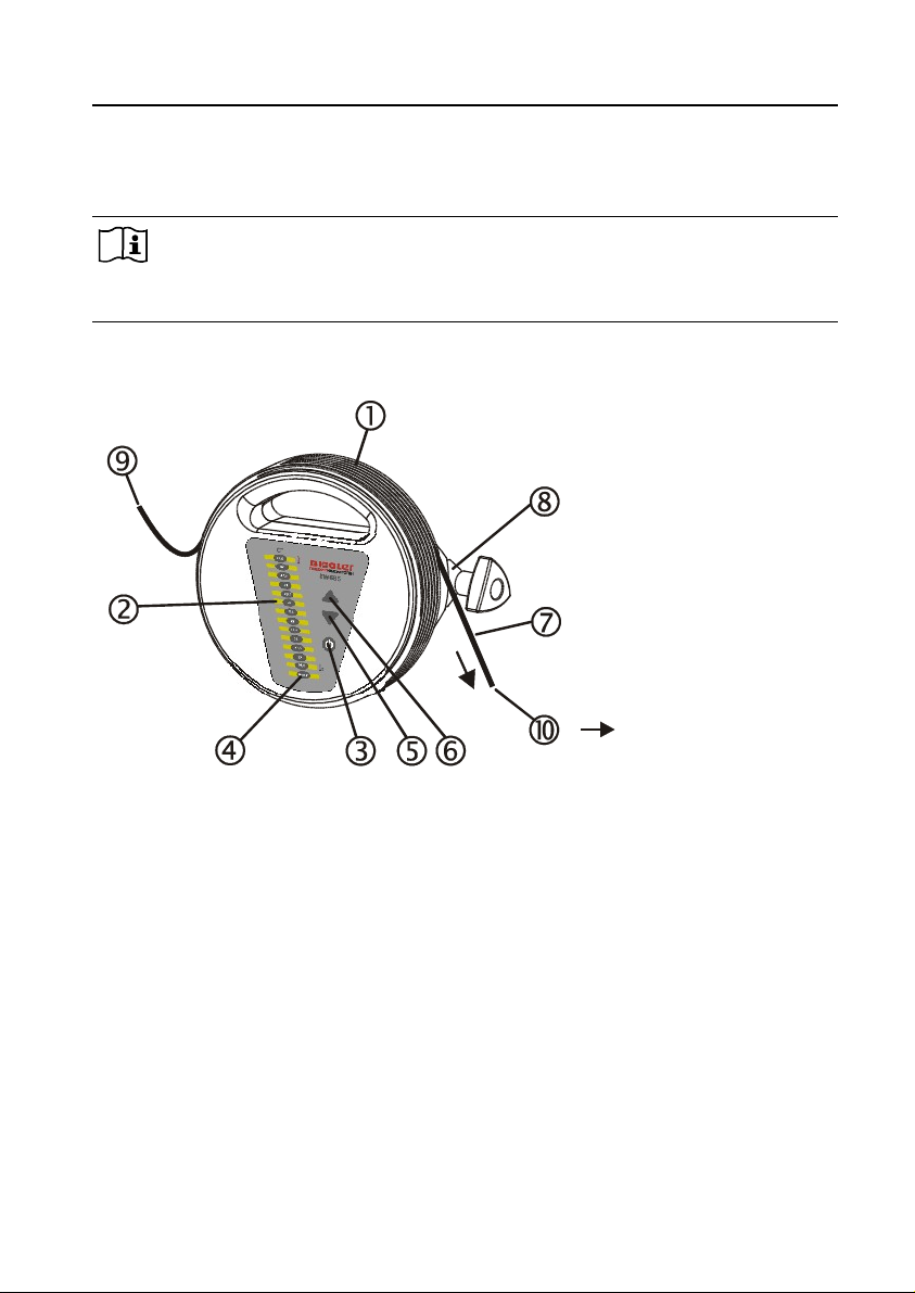
Diag. 1
1 Heat exchanger
2 emperature scale
3 Control ON / S ANDBY
4 LED S ANDBY
5 Control for decreasing the
temperature
6 Control for increasing the
temperature
7 Extension tube
8 Fixing clamp
9 Entry of liquid
10 Exit of liquid
Flow direction

Instructions for Use – BW 685 / BW 685 S BIEGLER
If a temperature other than 38.5°C is desired, it can be preset in the Standby
mode by using the controls and (Diag.1/5 and Diag.1/6). If an
adjustment control is pressed, the visual display indicates the existing preset
temperature. By repeated operation of the control or , the temperature
can be reset. Resetting of the temperature can only be performed in the
Standby mode.
he warmer of the BW 685 / BW 685 S can be started by pressing the
control (Diag.1/3). A self-test of safety relevant device functions is carried
out, which is terminated by a short acoustic signal. he BW 685 /
BW 685 S attains the set target temperature within 1 minute. he actual
temperature (+/- 0.5°C) is indicated on the display.
Select suitable consumable materials. See the section "Consumable
materials".
Prepare infusion or transfusion. Important: he length of the tube between
the BW 685 / BW 685 S and the patient must be at least 40 cm and the tube
must not be stretched.
Beginning at the back of the heat exchanger, gently pull the extension tube
and coil it in a counter-clockwise direction towards the front. It is advisable
that the distance between the BW 685 / BW 685 S and the patient does not
exceed much more than 80 cm.
Important: he tube must be completely inserted into the groove (Diag. 2)
he flow direction specified in diagram 1 must be complied with.
10 DE - Edition 02 / 2007
Diag. 2
Position of the tube in the groove of the heat
exchanger
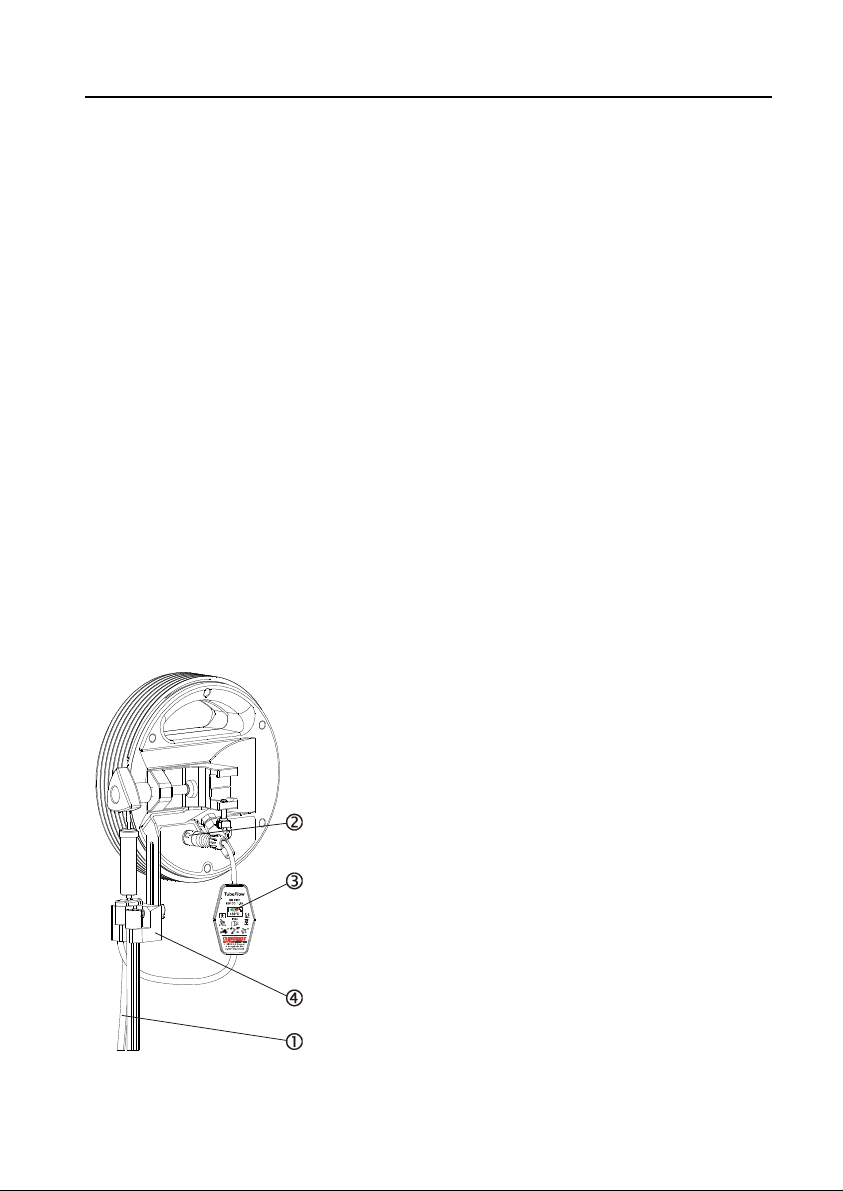
Diag.3
BIEGLER Instructions for Use – BW 685 / BW 685 S
Optional accessory tube warmer Biegler Tubeflow for BW 685 S:
he connector as per diagram 3/2 must be connected to the BW 685 S
before starting the optional tube warmer.
DE - Edition 02 / 2007 11
Insert the transfusion or infusion tube into the
groove of the tube warmer. Insert the tube over
the complete length of the Biegler ubeflow.
Important: Overwarming can result, if the full
length of the tube warmer is not utilised, thereby
possibly harming the medium or patient, since
the reference temperature sensor is located at
the distal end.
Diag. 3
1 ube warmer
2 Connector
3 Control light
(Green – Operational / red – Alarm)
Fixture

Instructions for Use – BW 685 / BW 685 S BIEGLER
he ubeflow is also activated when the BW 685 S is turned on; this is
indicated by a green control light on the ubeflow.
3.2 ALARMS
he BW 685 / BW 685 S can trigger two types of temperature alarm:
he low temperature alarm is activated when the temperature of the heat
exchanger drops below 36.5°C. he audio low temperature alarm is
deactivated during the first 60 seconds after switching on.
he high temperature alarm is activated when the temperature of the heat
exchanger exceeds 42.0°C. In this event visual and audio alarm signals are
given and the heating is switched off. o reset the device or switch off the
alarm, disconnect the device from the power supply.
Important: he temperature alarm can also be set off externally e.g. by
exposure to sunlight.
3.3 SHUTTIN DOWN THE DEVICE
After being used for treatment, the device is shut down as follows:
Switch the device into Standby mode using control (Diag.1/3).
Release pressure from the system by switching off possibly used pressure
cuffs or infusion pumps. Empty and disconnect the system as far as possible.
Remove the consumable materials from the heat exchanger (Diag.1/1) and, if
used, also from the optional tube warmer and dispose of in accordance with
the applicable local regulations
Disconnect the device from the power supply and clean and disinfect
according to the section "Cleaning and disinfection".
4 MAINTENANCE
he BW 685 / BW 685 S is designed as a low-maintenance device. o
preserve the quality and functional safety, please comply with the following
points:
12 DE - Edition 02 / 2007

BIEGLER Instructions for Use – BW 685 / BW 685 S
•Always keep the device clean (see the section: "Cleaning and
disinfection").
•he periodic technical safety inspections must be carried out (see the
section "Periodic inspections")
5 CLEANIN AND DISINFECTION
he BW 685 / BW 685 S and the optional tube warmer ubeflow may only be
cleaned using a soft cloth with a water-soluble, non-aggressive cleaning
agent or a special cleaning agent for plastics.
For the purposes of disinfection, ready-made alcohol-based spray
disinfectants can be used.
Important: Before cleaning or disinfecting, the device must always be
disconnected from the mains power supply by pulling the plug.
DE - Edition 02 / 2007 13

Instructions for Use – BW 685 / BW 685 S BIEGLER
Do not disinfect the device with steam (i.e. in autoclaves), hot air or
thermochemical cleaning solutions.
6 PERIODIC INSPECTIONS
he periodic technical safety inspections (according to the local standards in
force – e.g.. in Austria ÖVE/ÖNORM E 8751-1) must be carried out on the
BW 685 / BW 685 S at least every 12 months by persons able to carry out
such technical safety inspections based on their training, knowledge and
experience gained by practical activities.
he results of the periodic inspection are to be documented, together with the
date and the inspecting agency.
Important: Should a malfunction be evident, suitable warning signs should be
attached to the device to ensure that it cannot be used before necessary
service and repair work has been carried out.
CHECKIN THE WARM-UP PERIOD
his is the time taken by the BW 685 / BW 685 S to heat up to 38.5°C from
room temperature. he device is malfunctioning if it takes much longer than
one minute.
CHECKIN THE CONTROL TEMPERATURE
he control temperature is checked on the groove bed of the heat exchanger.
he sensor of a suitable contact thermometer (tolerance +/- 0.15°C) is fixed
to this position, e.g. by using a piece of infusion tubing. he examination is
performed at a temperature setting of 38.5°C.
he measured value is read after it has stabilised. he difference must not
exceed +/- 0.5°C. here is a malfunction if a difference from the control
temperature of greater than +/- 0.5°C is obtained.
CHECKIN THE LOW TEMPERATURE ALARM
Preheat the device to 38.5°C, then disconnect the mains plug. Hold down the
control and reconnect the mains power plug. After the beep has ceased,
release the control . Press the switch . he device is now in an
operational state where all the alarms are active, but the heating is switched
off. he BW 685 / BW 685 S now slowly cools down. When the temperature
drops below the 36.5°C threshold, the low temperature alarm should trigger.
14 DE - Edition 02 / 2007

BIEGLER Instructions for Use – BW 685 / BW 685 S
For reasons of safety, short beeping sounds are given at intervals of a
second in this operational mode and the S ANDBY indicator (Diag.1/4)
flashes. here is a malfunction if the low temperature alarm is not triggered.
CHECKIN THE HI H TEMPERATURE ALARM
Preheat the device to 41°C and wait for the temperature to stabilise, then
disconnect the mains plug. Hold down the control and reconnect the
mains power plug. After the beep has ceased, release the control . Press
the switch . he device now slowly heats up to a target temperature of
42.5°C. Observe the temperature display carefully. he high temperature
alarm should be triggered at a temperature of 42°C.
For reasons of safety, short beeping sounds are given at intervals of a
second in this operational mode and the S ANDBY indicator (Diag.1/4)
flashes. here is a malfunction if the high temperature alarm is not triggered.
VISUAL CHECK OF ENERAL CONDITION
he device should be checked for mechanical damage (general condition)
and for the completeness of the sticker information, particularly the device
label on the reverse. here is a malfunction if mechanical damage to the
device is evident which could be harmful or impair the functional operation of
the device.
ELECTRICAL SAFETY
All relevant electrical safety data should be checked, particularly the earth
conductor resistance ( arget: < 0.3 Ohm) and leakage current ( arget: < 0.75
mA). here is a malfunction if there is a measured value outside the
tolerances.
DE - Edition 02 / 2007 15

Instructions for Use – BW 685 / BW 685 S BIEGLER
7 MANUFACTURER LIABILITY
he manufacturer and the supplier of the device reject all liability if:
•the device is not used in accordance with the instructions for use
•the user is not sufficiently informed about the functioning of the device on
the basis of the instructions for use and the safety instructions
•repairs are not performed exclusively by the manufacturer or by persons
and service centres expressly authorised by the manufacturer
•the device is used in places in which the electrical installations do not
comply with the applicable national standards, or if power supply during
the period of use of the device is not guaranteed
•original spare parts material are not used or the maintenance interval
is not complied with.
•disposal of the device and its accessories is not carried out in
accordance with the applicable local regulations.
8 WARRANTY CONDITIONS
he manufacturer guarantees that all flaws of material and workmanship
which arise within 24 months from the date of purchase will be repaired free
of charge.
Claims are only accepted under the following terms:
•he manufacturer and/or supplier is informed immediately of the fault for
which the warranty claim is being made.
•he instructions of the manufacturer and/or supplier on storage or return
of the device are complied with.
•Presentation of a legible copy of the invoice for the device concerned,
showing the date of purchase.
•An exact description of the defects or malfunctions identified by the
customer.
16 DE - Edition 02 / 2007

BIEGLER Instructions for Use – BW 685 / BW 685 S
he manufacturer's warranty will be void if it is found that the maintenance,
disinfection and inspection instructions have not been followed according to
the instructions for use, the device has been damaged by force or operating
error or has been used in any way contrary to the instructions for use and
safety instructions. he warranty will also be void if original Biegler materials
were not used as replacement parts, or measures for repair were undertaken
by persons not authorised by the manufacturer or supplier.
If the manufacturer is required to meet a warranty claim in accordance with
these terms, the customer shall bear the costs and risks of transport of the
device from and to the place of use.
he manufacturer and/or supplier shall under no circumstances assume
liability for slight negligence. he compensation for lost earnings and profits is
likewise excluded.
9 RETURN OF DEVICES
Devices must be carefully cleaned and disinfected before being placed in the
original packaging for returning.
If the original packaging is no longer available, the product has to be suitably
packaged for the method of dispatch.
DE - Edition 02 / 2007 17
Instructions for Use – BW 685 / BW 685 S BIEGLER
10 ELECTROMA NETIC COMPLIANCE
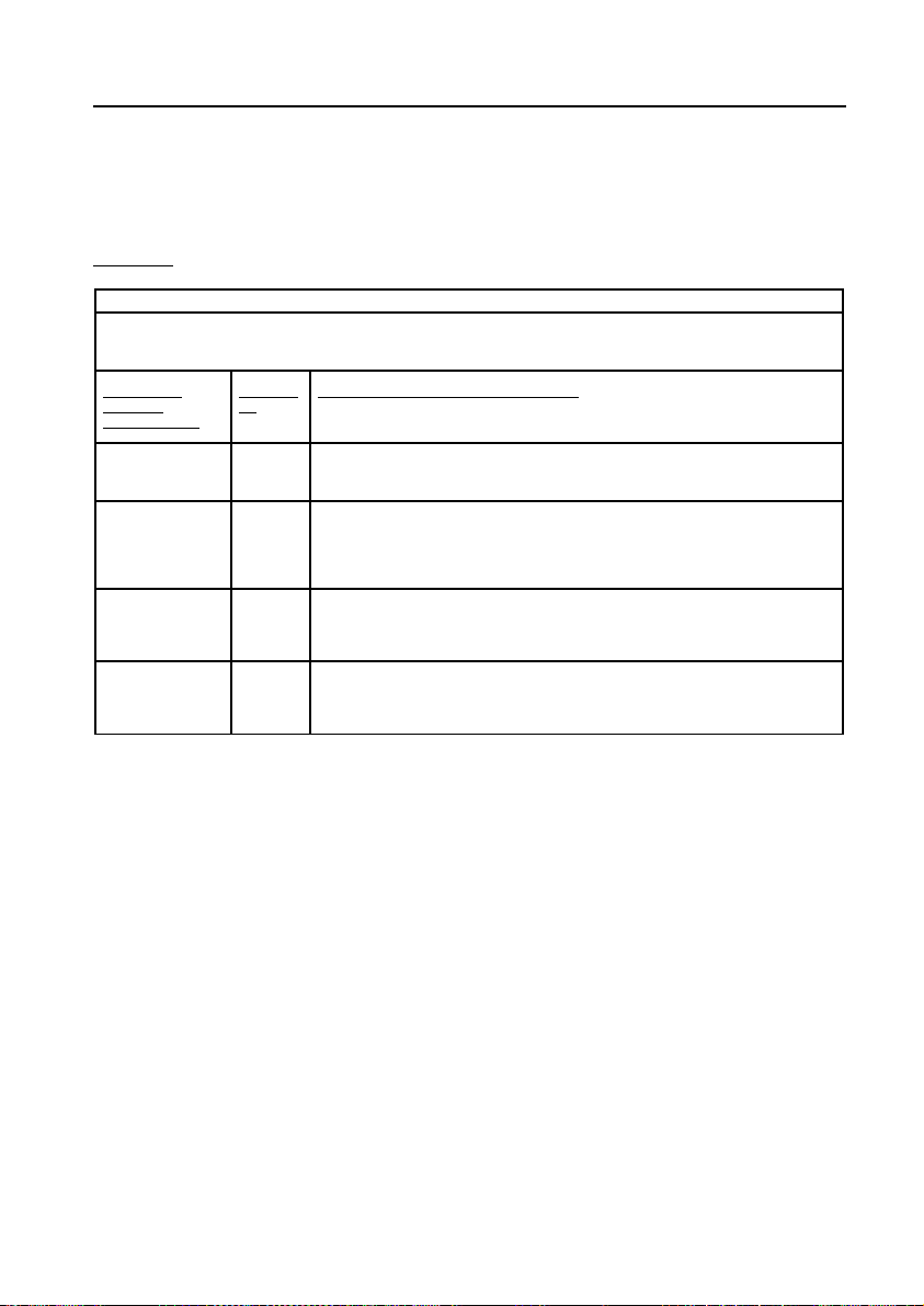
Table 201
uidelines and manufacturer's declaration – electromagnetic emission
he BW685 is intended for use in the environment specified below. he customer or the user of the BW685 should assure
that it is used in such an environment.
Interference
emission
measurements
Complian
ce
Electromagnetic environment - guidelines
RF emissions acc.
to CISPR 11
Group 1 he BW685 uses RF energy only for its internal function. herefore, its RF emissions are
very low and are not likely to cause any interference in nearby electronic equipment.
RF emissions acc.
to CISPR 11
Class B he BW685 is suitable for use in all establishments, including domestic establishments
and those directly connected to the public power supply network that also supplies
buildings used for domestic purposes.
Emission of
harmonics acc. to
IEC 61000-3-2
Class A
Emission of
harmonics acc. to
IEC 61000-3-3
Complies
18 DE - Edition 02 / 2007

BIEGLER Instructions for Use – BW 685 / BW 685 S
Table 202
uidelines and manufacturer's declaration – electromagnetic interference resistance
he BW685 is intended for use in the electromagnetic environment specified below. he customer or the user of the BW685
should assure that it is used in such an environment.
Interference
resistance test
IEC 60601-
test level
Compliance level Electromagnetic environment - guideline
Electrostatic discharge
(ESD) acc. to
IEC 61000-4-2
± 6 kV contact
discharge
± 8 kV air discharge
± 6 kV contact discharge
± 8 kV air discharge
Floors should be wood, concrete or ceramic
tile. If floors are covered with synthetic
material, the relative humidity should be at
least 30%.
Fast transient
/electrical bursts acc.
to IEC 61000-4-4
± 2 kV for power
supply lines
± 1 kV for
input/output lines
± 2 kV for power supply
lines
he mains power supply quality should be that
of a typical commercial or hospital
environment.
Surge voltages
(surges) acc. to
IEC 61000-4-5
± 1 kV differential
mode
± 2 kV common
mode
± 1 kV normal mode voltage
± 2 kV common mode
voltage
he mains power supply quality should be that
of a typical commercial or hospital
environment.
Voltage dips, short
interruptions and
voltage variations of
the supply voltage
acc. to
IEC 61000-4-11
< 5% U (> 95% dip
in U )
for ½ cycle
40% U (60% dip in
U)
for 5 cycles
70% U (30% dip in
U)
for 25 cycles
< 5% U (> 95% dip
in U )
for 5 s
< 5% U (> 95% dip in U )
for ½ cycle
40% U (60% dip in U )
for 5 cycles
70% U (30% dip in U )
for 25 cycles
< 5% U (> 95% dip in U )
for 5 s
he mains power supply quality should be that
of a typical commercial or hospital
environment.
If the use of the BW685 requires continued
operation during power mains interruptions, it
is recommended that the BW685 be powered
from an uninterruptible power supply or a
battery.
Power frequency (50
Hz/60 Hz) magnetic
field acc. to IEC
61000-4-8
3 A/m 3 A/m Power frequency magnetic fields should be at
levels characteristic of a typical location in a
typical commercial or hospital environment.
Note U is the AC mains voltage prior to application of the test level.
DE - Edition 02 / 2007 19

Instructions for Use – BW 685 / BW 685 S BIEGLER
Table 204
uidelines and manufacturer's declaration – electromagnetic interference resistance to
he BW685 is intended for use in the electromagnetic environment specified below. he customer or the user of the BW685
should assure that it is used in such an environment.
Interference
resistance test
IEC 60601-
test level
Compliance
level
Electromagnetic environment - guidelines
Portable and mobile RF communications equipment should be
used no closer to any part of the BW685, including cables,
than the recommended protection distance calculated from the
equation applicable to the frequency of the transmitter:
Recommended protection distance:
Conducted RF
disturbance variables
acc. to IEC 61000-4-6
3 Veff
150 kHz to 80
MHz
1V
in V
P
V
d
∗
=
1
5,3
Emitted RF
disturbance variables
acc. to
IEC 61000-4-3
3 V/m
80 kHz to 2.5
GHz
1E
in
V/m
P
E
d
∗
=
1
5,3
for 80 MHz to 800 MHz
P
E
d
∗
=
1
7
for 800 MHz to 2.5 GHz
Where P is the maximum output power rating of the transmitter
in watts (W) according to the transmitter manufacturer and d is
the recommended protection distance in metres (m).
Field strengths from fixed RF transmitters, as determined by
an electromagnetic site surveya should be less than the
compliance level in each frequency rangeb.
Interference may occur in the vicinity of equipment marked
with the following symbol:
NO E 1 At 80 MHz and 800 MHz, the higher frequency range applies.
NO E 2 hese guidelines may not apply in all situations. Electromagnetic propagation is affected by
absorption and reflection from structures, objects and people.
aField strengths from stationary transmitters, such as base stations for radio (cellular /cordless) telephones and
land mobile radios, amateur radio, AM and FM radio broadcast and V broadcast cannot be predicted
theoretically with accuracy. o assess the electromagnetic environment due to stationary RF transmitters,
an electromagnetic site survey should be considered. If the measured field strength in the location in which
the BW685 is used exceeds the applicable RF compliance level as specified above, the BW685 should be
observed to verify normal operation. If abnormal performance is observed, additional measures may be
necessary, such as reorienting or relocating the BW685.
bOver the frequency range 150 kHz to 80 MHz, field strengths should be less than [V1] V/m.
20 DE - Edition 02 / 2007
Other manuals for BW 685
2
This manual suits for next models
1
Table of contents
Other Biegler Medical Equipment manuals


Popular Medical Equipment manuals by other brands


Getinge
Getinge Arjohuntleigh Nimbus 3 Professional Instructions for use

Mettler Electronics
Mettler Electronics Sonicator 730 Maintenance manual

Pressalit Care
Pressalit Care R1100 Mounting instruction

Denas MS
Denas MS DENAS-T operating manual

bort medical
bort medical ActiveColor quick guide

AccuVein
AccuVein AV400 user manual


