Bien Air CHIROPRO User manual

REF 2100318-0003/2019.12© Bien-Air Dental
Rx Only
CHIROPRO 3rd Gen
ENG INSTRUCTIONS FOR USE.
FRA INSTRUCTIONS D’UTILISATION.
DEU BEDIENUNGSANLEITUNG.
ESP INSTRUCCIONES DE USO.
ITA ISTRUZIONI PER L’USO.
PRT INSTRUÇÕES DE UTILIZAÇÃO.
RUS ИНСТРУКЦИЯ ПО ЭКСПЛУАТАЦИИ.
中文 使用说明书 .
JPN 取扱説明書 .

REF 2100318-0003/2019.12 © Bien-Air Dental
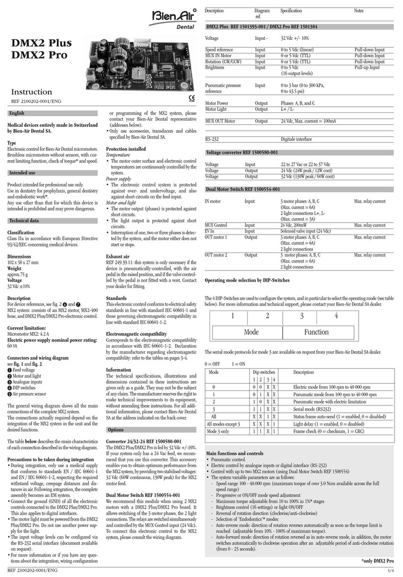
Set Chiropro 3rd Gen REF 1700708-001
REF 1600995-001 REF 1303393-001 REF 1601008-001 REF 1601009-001 REF 1600631-001 REF 1500984-005 REF 1307727-010
REF 1301575-001 REF 1502329-002
Set Chiropro 3rd Gen CA REF 1700707-001
REF 1700708-001 REF 1600692-001
Set Chiropro 3rd Gen KM REF 1700737-001
REF 1600995-001 REF 1303393-001 REF 1601008-001 REF 1601009-001 REF 1600631-001 REF 1501635-010 REF 1307727-010
REF 1301575-001 REF 1502329-002
Set Chiropro 3rd Gen KM CA REF 1700736-001
REF 1700737-001 REF 1600786-001
Options
REF 1601008-001 REF 1600692-001 REF 1600598-001 REF 1600785-001 REF 1600786-001 REF 1600052-001 REF 1303393-001 REF 1601009-001
REF 1600631-001 REF 1301575-001 REF 1502329-002 REF 1307727-010 REF 1307312-010 REF 1500984-010 REF 1501738-010 REF 1501635-010
REF 1501621-010 REF 1307031-001

ENG
1
1 Symbols............................................................. 2
1.1 Description of symbols for Chiropro 3rd Gen units ...................2
1.2 Description of symbols for Chiropro 3rd Gen accessories .....2
2 Identification, Intended Use and Notation... 3
2.1 Identification..........................................................................................3
2.2 Intended use ..........................................................................................3
2.3 Notation and chapter links................................................................3
3 Warnings & Precautions of Use .................... 4
4 Description........................................................ 5
4.1 Chiropro 3rd Gen system overview ................................................5
4.2 Sets supplied.........................................................................................6
4.3 Options ....................................................................................................6
4.4 Technical data .......................................................................................6
4.5 Environmental protection and information for disposal..........7
4.6 Electromagnetic compatibility (technical description) .............7
4.6.1 Precautions of use ................................................................7
4.6.2 Electromagnetic compatibility warnings .......................7
4.6.3 Electromagnetic compatibility – emissions &
immunity .....................................................................................8
5 Installation.....................................................10
5.1 Install the Chiropro 3rd Gen system ............................................ 11
5.2 On/off procedure............................................................................... 11
6 Interface overview......................................... 12
6.1 Chiropro 3rd Gen modes.................................................................. 12
6.2 Rotating knob functions overview................................................ 12
6.3 Sound alerts ....................................................................................... 13
7 Operation.........................................................14
7.1 Operation screen description ........................................................ 14
7.2 Perform an operation, steps P1 and P2 ..................................... 14
7.3 Perform an operation, steps P3, P4 and P5.............................. 14
8 Settings ........................................................... 16
8.1 MX-i LED 3rd Gen micromotor speed .......................................... 16
8.2 MX-i LED 3rd Gen micromotor torque ......................................... 16
8.3 MX-i LED 3rd Gen micromotor rotation direction..................... 16
8.4 Irrigation level.................................................................................... 17
8.5 Contra-angle ratio............................................................................. 17
9 Special modes................................................ 18
10 List of errors & Troubleshooting ...............20
10.1 Safety warning (operating)............................................................. 20
10.2 Device operating error..................................................................... 21
11 Maintenance ..................................................22
11.1 Servicing.............................................................................................. 22
11.2 Cleaning & disinfection.................................................................... 22
11.3 Important............................................................................................. 22
11.4 Replacement of fuses...................................................................... 23
12 General information and guarantee..........24
12.1 General information ......................................................................... 24
12.2 Terms of guarantee .......................................................................... 24
Table of contents

2
1.1 Description of symbols for Chiropro 3rd Gen units
1.2 Description of symbols for Chiropro 3rd Gen accessories
Symbol Description Symbol Description
CE Marking with number of the notified body. Recyclable materials.
Main switch - Power OFF. Separate collection of electric and electronic
equipment.
Main switch - Power ON. Manufacturer.
Fuse Ø 5 x 20 mm. Light.
Alternating current. Sound alerts.
RF emitting device (Interference may occur in the
vicinity of equipment marked with this symbol).
Warning: in accordance with federal law (USA), this
device is only available for sale upon recommen-
dation by an accredited practitioner.
CAUTION! Consult accompanying documents.
Provides an instruction that should be observed for
safety reasons.
CSA marking - Complies with U.S. and Canadian
standards.
Refer to the accompanying documents (www.bie-
nair.com/ifu). Serial number.
Reference number.
Symbol Description Symbol Description
CE Marking with number of the notified body. Thermo washer disinfectable.
Expiration date. Recyclable materials.
Do not reuse. Separate collection of electric and electronic
equipment.
Sterilized with Ethylene Oxyde. Sterilizable in autoclave up to the specified tem-
perature.
Electrical safety. Applied part type B. Manufacturer.
Reference number. Serial number.
Rx Only
SN
REF
STERILE
EO
135°C
REF
SN
1Symbols

ENG
3
2 Identification, Intended Use and Notation
2.1 Identification
Electronically controlled tabletop device for dentistry allowing
operation of a dental handpiece via an MX-i LED 3rd Gen
micromotor with variable speed control by a pedal.
A peristaltic pump conveys the physiological liquid via a
disposable irrigation line without being contaminated.
The device's LCD display indicates and allows to control operation
settings.
2.2 Intended use
The equipment is to be used by dentists and surgeons in dental
offices and hospitals. The system is designed to control a dental
MX-i LED 3rd Gen micromotor only which can drive a dental hand-
piece fitted with appropriate tools to cut hard and soft tissues in
the oral cavity and to place dental implants.
The system is intended for use in dentistry for implantology.
Any use other than that for which this product is intended is
unauthorized and may be dangerous.
The system meets all the current legal requirements for medical
devices.
The intended electromagnetic environment (per IEC 60601-1-2
ed. 4.0) is Professional healthcare facility environment.
2.3 Notation and chapter links
•A, B, C, etc.
Text preceded by a letter indicates a procedure to be carried
out step-by-step.
•
Indicates a procedure result.
•(1),(2),(3), etc.
Text preceded by a number indicates text used in
conjunction with an illustration.
•OK,Settings, etc.
Text in bold italic font style indicates, on-screen elements
such as buttons, menus, menu items, screen areas, values,
fields when they are named and screen names.
In order to simplify the notation, in this manual:
• «Clockwise» is referred to as «CW»;
• «Counterclockwise» is referred to as «CCW»;
• Forward micromotor rotation mode is referred to as «FWD»;
• Reverse micromotor rotation mode is referred to as «REV»;
• Rotational speed unit «revolutions per minute» is referred to
as «rpm»;
• Torque unit «newton centimetre» is referred to as «Ncm»;
• Micromotor control unit is referred to as «DMX».

4
3 Warnings & Precautions of Use
CAUTION
The power plug is used for disconnection in case of problems, it
must be easily accessible at all times.
CAUTION
Never connect a handpiece on a running MX-i LED 3rd Gen
micromotor.
CAUTION
Any modification of the medical device is strictly forbidden.
CAUTION
The device is not designed for use in an explosive atmosphere
(anaesthetic gas).
CAUTION
Do not attempt to open the device when it is connected to the
electric mains.
Risk of electrocution.
CAUTION
The parameters contained in the dental procedures are indicative
only. Bien-Air Dental SA cannot be held liable for them.
CAUTION
The device must not be touched by the patient.
CAUTION
Do not simultaneously touch the patient and the pump or contacts
of connectors.
CAUTION
Ensure that there is no water under the unit before switching it
on.
CAUTION
All connectors must be dry before use. Ensure the absence of
residual moisture due to cleaning.
WARNING
To avoid the risk of electric shock, this equipment must only be
connected to a supply mains with protective earth.

ENG
5
4 Description
4.1 Chiropro 3rd Gen system overview
FIG. 1
(1) Peristaltic pump lid
(2) Pedal connector
(3) Marking
(4) Bracket support
(5) Main switch
(6) Fuse box
(7) Mains connector
(8) MX-i
LED
3rd Gen micromotor
(9) Button to start/stop irrigation
(10)
Foot control to reverse the rotation of the MX-i LED
3rd Gen
micromotor
(11) “Program” button to go to next operation step
(12) Motor start
(13) MX-i
LED
3rd Gen micromotor connector
(14) Control knob
(15) LCD control screen
8
24
356
7
3
13
1
9
11
12
10
1415

6
4.2 Sets supplied
Chiropro 3rd Gen set REF 1700708-001
Chiropro 3rd Gen CA set REF 1700707-001
Chiropro 3rd Gen KM set REF 1700737-001
Chiropro 3rd Gen KM CA set REF 1700736-001
4.3 Options
4.4 Technical data
Dimensions L x W x H
Chiropro 3rd Gen unit ..............................240 x 240 x 102 mm
Chiropro 3rd Gen unit (with bracket)...240 x 240 x 482 mm
Pedal ............................................................250 x 205 x 54 mm
Pedal (with handle)..................................250 x 205 x 144 mm
Motor cable (REF 1601009)...................L 2.0 m
Pedal cable.................................................L 2.9 m
The pedal is waterproof (IP X8 in accordance with IEC 60529).
Weight
Chiropro 3rd Gen unit ..............................2.2 kg
Pedal ............................................................830 g
Bracket ........................................................115 g
Cable ............................................................105 g
Electrical data
Voltage.........................................................100 – 240 VAC
Frequency ..................................................50-60 Hz
Environmental conditions
Designation REF number
Chiropro 3rd Gen unit (1x) 1600995-001
MX-i
LED
3rd
Gen micromotor (1x) 1601008-001
3-button pedal (1x) 1600631-001
Cable MX-i LED 3rd Gen (2m) (1x) 1601009-001
Sterile protective sheet (2x) 1502329-002
Pack of 5 disposable sterile irrigation lines 1500984-005
Pack of 10 attachment collars for fastening
the sterile irrigation line to a cable 1307727-010
Bracket for fluid bottle (1x) 1303393-001
Handpiece support (1x) 1301575-001
3P cable system, US/Asia, length 2m (1x) 1300067-001
3P cable system, Europe, length 2.5 m (1x) 1300066-001
3P cable system, Switzerland, length 2 m (1x) 1300065-001
Designation REF number
Chiropro 3rd Gen set (1x) 1700708-001
Contra-angle handpiece CA 20:1 L Micro-
Series (light) (1x) 1600692-001
Designation REF number
Chiropro 3rd Gen unit (1x) 1600995-001
MX-i
LED
3rd
Gen micromotor (1x) 1601008-001
3-button pedal (1x) 1600631-001
Cable MX-i LED 3rd Gen (2m) (1x) 1601009-001
Sterile protective sheet (2x) 1502329-002
Kirschner/Meyer pack of 10 disposable ste-
rile lines 1501635-010
Pack of 10 attachment collars for fastening
the sterile irrigation line to a cable 1307727-010
Bracket for fluid bottle (1x) 1303393-001
Handpiece support (1x) 1301575-001
3P cable system, US/Asia, length 2m (1x) 1300067-001
3P cable system, Europe, length 2.5 m (1x) 1300066-001
3P cable system, Switzerland, length 2 m (1x) 1300065-001
Designation REF number
Chiropro 3rd Gen KM set (1x) 1700737-001
Contra-angle handpiece CA 20:1 L KM
Micro-Series (light) 1600786-001
Designation REF number
3-button pedal 1600631-001
MX-i LED 3rd Gen micromotor 1601008-001
Contra-angle handpiece CA 20:1 L KM
Micro-Series (light) 1600786-001
Contra-angle handpiece CA 20:1 L KM (light) 1600785-001
Contra-angle handpiece CA 20:1 L
Micro-Series (light) 1600692-001
Contra-angle handpiece CA 20:1 L (light) 1600598-001
Straight handpiece PM 1:1 Micro-Series 1600052-001
Sterile protective sheet 1502329-002
Pack of 10 disposable sterile lines 3.5 m 1501738-010
Kirschner/Meyer pack of 10 disposable ste-
rile lines 1501635-010
Kirschner/Meyer type detachable irrigation set
for CA 20:1 L KM and CA 20:1 L KM
Micro-Series, comprising 10 rings and 10 tubes
1501621-010
Pack of 10 disposable sterile lines 1500984-010
Bracket for fluid bottle 1303393-001
Handpiece support 1301575-001
Cable MX-i LED 3rd Gen (2m) 1601009-001
3P cable system, US/Asia, length 2m 1300067-001
3P cable system, Europe, length 2.5 m 1300066-001
3P cable system, Switzerland, length 2 m 1300065-001
Pack of 10 attachments collars for fastening
the sterile irrigation line to a cable 1307727-010
Pack of 10 fuses T4.0AH 250 VAC high brea-
king capacity 1307312-010
Knob 1307031-001
Environmental
conditions
Operating Transport and storage
(max. 15 weeks)
Temperature +5°C (41°F) to
+35°C (95°F)
-25°C (-13°F) to
+70°C (158°F)

ENG
7
CAUTION
Do not use Chiropro 3rd Gen outside the range of operating
temperature.
Classification
Class IIa in accordance with European Directive 93/42/EEC
concerning medical devices.
Electric insulation class
Class I per IEC 60601-1 (apparatus protected against electric shocks).
CAUTION
The device must be only used by the operator.
Applied parts (per IEC 60601-1):
MX-i LED 3rd Gen micromotor..............REF 1601008-001
Straight handpiece 1:1 ...........................REF 1600052-001
CA 20:1 L.....................................................REF 1600598-001
CA 20:1 L Micro-Series...........................REF 1600692-001
CA 20:1 L KM..............................................REF 1600785-001
CA 20:1 L KM Micro-Series....................REF 1600786-001
Irrigation lines...........................................REF 1500984-010
KM Irrigation lines....................................REF 1501635-010
Degree of ingress protection
IP 41 (protection against insertion of objects larger than 1 mm
and dripping water (vertically falling drops)).
Memory
Memory storage of 5 steps settings including adjustment of
speed, torque, rotation direction, irrigation, and contra-angle ratio
for each step.
Languages
English.
Bracket for physiological liquid flask
Stainless steel.
Peristaltic pump
Pump delivery...........................................From 30 to 150 ml/min.
(5 levels)
Hose for pump ..........................................External Ø 5.60 mm
.......................................................................Internal Ø 2.40 mm
Wall thickness ...........................................1.60 mm
Intended for use with: See instructions for use
MX-i LED 3rd Gen micromotor..............REF 2100245
Cable MX-i LED 3rd Gen ..........................REF 2100163
Contra-angle CA 20:1 L, light................REF 2100209
Contra-angle CA 20:1 L
Micro-Series, light....................................REF 2100209
Contra-angle CA 20:1 L KM, light.........REF 2100209
Contra-angle CA 20:1 L KM
Micro-Series, light....................................REF 2100209
Straight Handpiece 1:1...........................REF 2100046
CAUTION
The use of the system with other handpieces, motors
or cables has not been validated/certified (speed and torque
values are not guaranteed in this case).
List of errors & Troubleshooting
See chapter “10 List of errors & Troubleshooting” on page 20.
4.5 Environmental protection and
information for disposal
The disposal and/or recycling of materials must be performed in
accordance with the legislation in force.
Separate collection of electric and electronic equipment and
accessories in view of recycling.
Electrical and electronic equipment may contain dangerous
substances which constitute health and environmental hazards.
The user must return the device to its dealer or establish direct
contact with an approved body for treatment and recovery of this
type of equipment (European Directive 2002/96/EC).
4.6 Electromagnetic compatibility
(technical description)
4.6.1 Precautions of use
This electronic control is in compliance with electrical safety
standards in line with standard IEC 60601-1, edition 3.1, and
those governing electromagnetic compatibility in line with
standard IEC 60601-1-2, fourth edition.
CAUTION
The device must be used by a competent person, in particular in
compliance with the legal provisions in force regarding
occupational safety, health and accident prevention measures,
and the current instruction for use. According to these measures,
the user has the following obligations:
• to only use devices that are in perfect working order
• to make sure that the device is used solely for the purpose
for which it is intended
• avoid contact with liquids.
4.6.2 Electromagnetic compatibility
warnings
CAUTION
The Chiropro 3rd Gen complies with the EMC requirements
according to IEC 60601-1-2. Radio transmitting equipment,
cellular phones, etc., should not be used in the immediate vicinity
of the device, since this could affect its operation. The device is
not suitable for being used close to high-frequency surgical
equipment, magnetic resonance imaging (MRI) and other similar
devices where the intensity of electromagnetic disturbances is
high. In any case, ensure that no high frequency cables are routed
above or near the device. If in doubt, contact a qualified technician
or Bien-Air Dental SA.
Portable RF communications equipment (including peripherals
such as antenna cables and external antennas) should be used no
closer than 30 cm (12 inches) to any part of the Chiropro 3rd Gen,
including cables specified by the manufacturer. Otherwise,
degradation of the performance of this equipment could result.
CAUTION
The use of accessories, transducers and cables other than those
specified, with the exception of transducers and cables sold by
Bien-Air Dental SA as spare parts for internal components, may
result in increased emissions or decreased immunity.
Relative humidity
(including
condensation)
30% to 80% 10% to 100%
Atmospheric
pressure
700 hPa to
1060 hPa 500 hPa to 1060 hPa
Environmental
conditions
Operating Transport and storage
(max. 15 weeks)

8
4.6.3 Electromagnetic compatibility – emissions & immunity
Guidance and manufacturer’s declaration – Electromagnetic emissions
The Chiropro 3rd Gen is intended for use in the electromagnetic environment specified below. The customer or the user of the Chiropro 3rd
Gen must ensure that it is actually used in such an environment.
Guidance and manufacturer’s declaration – Electromagnetic immunity
The Chiropro 3rd Gen is intended for use in the electromagnetic environment specified below. The customer or the user of the Chiropro 3rd
Gen must ensure that it is actually used in such an environment.
Emissions test Compliance Electromagnetic environment - guidance
RF emissions CISPR 11 Group 1
The Chiropro 3rd Gen uses RF energy for its internal operation only. Therefore, its RF
emissions are very low and are not likely to cause any interference in nearby electronic
equipment.
RF emissions CISPR 11 Class B
The Chiropro 3rd Gen is suitable for use in any building, including residential buildings
and those directly connected to the public low-voltage power supply network that sup-
plies buildings used for residential purposes.
Harmonic emissions IEC
61000-3-2 Class A
Emissions due to voltage
fluctuations IEC 61000-3-3 Conforming
Immunity test IEC 60601 test level Compliance level Electromagnetic
environment - guidance
Electrostatic discharge
(ESD)
IEC 61000-4-2
±8 kV contact
±2 kV air
±4 kV air
±8 kV air
±15 kV air
±8 kV contact
±2 kV air
±4 kV air
±8 kV air
±15 kV air
Floors should be wood,
concrete or ceramic tile. If
floors are covered with
synthetic material, the
relative humidity should be
at least 30%.
Electrical fast transient/
burst
IEC 61000-4-4
±2 kV for power supply lines
±1 kV for other lines
±2 kV for power supply lines
N.A.
Mains power quality should
be that of a commercial or
hospital environment.
Surge
IEC 61000-4-5
±0.5 kV line to line
±1 kV line to line
±0.5 kV line to earth
±1 kV line to earth
±2 kV line to earth
±0.5 kV line to line
±1 kV line to line
±0.5 kV line to earth
±1 kV line to earth
±2 kV line to earth
Mains power quality should
be that of a commercial or
hospital environment.
Voltage dips, short inter-
ruptions and voltage varia-
tions on power supply
input lines
IEC 61000-4-11
0% UTfor 0.5 cycle, at 0°, 45°, 90°,
135°, 180°, 225°, 270° and 315°
0% UTfor 1 cycle and
70% UTfor 25/30 cycles at 0°
0% UTfor 250 cycles at 0°
0% UTfor 0.5 cycle, at 0°, 45°, 90°,
135°, 180°, 225°, 270° and 315°
0% UTfor 1 cycle and
70% UTfor 25/30 cycles at 0°
0% UTfor 250 cycles at 0°
Mains power quality should
be that of a commercial or
hospital environment. If the
user of the Chiropro 3rd
Gen requires continued
operation during mains
power interruptions, it is
recommended that the
Chiropro 3rd Gen be powe-
red from an uninterruptible
power supply or a battery.
Magnetic field due to mains
frequency (50/60 Hz)
IEC 61000-4-8
30 A/m 30 A/m
Magnetic fields generated
by the mains frequency
should be at levels charac-
teristic of a typical location
in a typical commercial or
hospital environment.

ENG
9
Conducted disturbances
induced by RF fields
IEC 61000-4-6
3 VRMS
0,15 MHz – 80 MHz
6 VRMS in ISM bands
0,15 MHz – 80 MHz
80% AM at 1 kHz
3 VRMS
0,15 MHz – 80 MHz
6 VRMS in ISM bands
0,15 MHz – 80 MHz
80% AM at 1 kHz
Field strengths from fixed
RF transmitters, as deter-
mined by an electromagne-
tic site surveyashould be
less than the compliance
level in each frequency
range.
Interference may occur in
the vicinity of equipment
marked with the following
symbol:
Radiated RF EM fields
IEC 61000-4-3
3 V/m
80 MHz – 2,7 GHz
80 % AM at 1 kHz
3 V/m
80 MHz – 2,7 GHz
80 % AM at 1 kHz
Proximity fields from RF
wireless communications
equipment
IEC 61000-4-3
Test freq. [MHz] Max. power [W] Immunity test level
[V/m]
Distance: 0.3 m
385 1.8 27
450 228
710, 745, 780 0.2 9
810, 870, 930 228
1720, 1845, 1970 2 28
2450 228
5240, 5500, 5785 0.2 9
NOTE: UTis the AC mains voltage prior to application of the test level.
Essential performance per IEC 60601-1: The essential performance is to maintain the visual luminous intensity of the LED and the
motor speed. The maximum speed deviation is ±5%.
a. Field strengths from fixed transmitters, such as base stations for radio (cellular/cordless) telephones and mobile field radios, amateur radios, AM and FM radio
broadcasts and TV broadcasts cannot be predicted theoretically with accuracy. To assess the electromagnetic environment due to fixed RF transmitters, an elec-
tromagnetic site survey should be considered. If the measured field strength in the location in which the Chiropro 3rd Gen is used exceeds the RF compliance
level mentioned above, the Chiropro 3rd Gen should be observed to verify that it is operating normally. If abnormal operation is observed, additional measures
may be necessary, such as reorienting or relocating the Chiropro 3rd Gen.
Immunity test IEC 60601 test level Compliance level Electromagnetic
environment - guidance

10
FIG. 1 FIG. 2 FIG. 3 FIG. 4
1 2
1
1
2
FIG. 5 FIG. 6 FIG. 7 FIG. 8
12
AAAA-MM-JJ
1 2 3
FIG. 9 FIG. 10 FIG. 11
5 Installation

ENG
11
5.1 Install the Chiropro 3rd Gen system
FIG. 1
A. Place the Chiropro 3rd Gen on a flat surface capable of bearing
its weight.
CAUTION
It may be positioned on a table, on a trolley or any other surface
but in no circumstances on the floor.
FIG. 2
B.
The fuse box may be opened with a screwdriver.
100 - 240 VAC = fuse T4.0AH 250 VAC REF 1307312-010.
To replace a fuse, see chapter“11.4 Replacement of fuses” on
page 23.
C.
Connect the power cable (1) to the connector (2).
Note 1
CAUTION
The power plug is used for disconnection in case of problems, it
must be easily accessible at all times.
FIG. 3
D.
Connect the pedal cable to the input provided on the rear panel,
guiding the connector and plug by means of the index pin on the
connector.
CAUTION
Do not lift the pedal holding the connection cable.
To disconnect the pedal cable pull the cable socket connector (1).
Do not pull the cable (2) without disconnecting the cable socket
before.
FIG. 4
E.
Connect the MX-i LED
3
rd Gen
micromotor cable to the motor
output, guiding the connector and plug by means of the index pin on
the connector.
FIG. 5
F.
Align and attach the bracket to the housing provided on the rear
of the console and suspend the flask or bottle.
FIG. 6
G.
Check the packaging integrity, as well as the expiry date of the
irrigation line on the label (1).
CAUTION
The medical device must be used only with lines supplied by
Bien-Air Dental to ensure trouble-free operation. These lines are
sterile and for single use. Re-use may result in microbiological
contamination of the patient.
H.
Remove the single-use sterile irrigation line (2) from its pouch.
FIG. 7
I.
Connect the flexible hose of the irrigation line to the spray tube of
the handpiece or contra-angle.
FIG. 8
J.
Install the peristaltic cassette (1) in the peristaltic pump (2).
Check that the cassette is clipped correctly.
FIG. 9
K.
Close the pump lid (3). If there is resistance to closing, open the
lid again and check the correct positioning of the cassette. When the
lid is correctly closed, the user should hear a click sound.
CAUTION
Do not run the pump while the lid is open.
CAUTION
Do not run the pump without irrigation line.
CAUTION
Risk of pinching!
FIG. 10
L.
Perforate the cap of the physiological liquid flask with the pointed
end of the irrigation line after removing the protective cap.
CAUTION
There is no detection of empty physiological liquid flask! Always
check the content of the flask before operating.
FIG. 11
M.
Attach the irrigation line on the motor cable using the 3
attachment collars REF 1307727-010.
5.2 On/off procedure
The device can be switched on and off in complete safety using
the main switch on the Chiropro 3rd Gen.
CAUTION
Do not switch off the device while the motor is running.
NOTES
1The equipment is powered by the mains power supply (100 -
240 VAC / 150W / 50-60Hz).

12
6 Interface overview
FIG. 1 FIG. 2
6.1 Chiropro 3rd Gen modes
The Chiropro 3rd Gen allows to visualize and control operation
parameters by the means of the LCD display.
A unique screen allows to use the following modes:
FIG. 1
• Operation mode (to perform an operation in 3 steps)
See chapter “7 Operation” on page 14 for details.
FIG. 2
• Settings mode (to set up operation parameters)
See chapter “8 Settings” on page 16 for details.
FIG. 3
• Special modes (to test system and reset settings)
See chapter “9 Special modes” on page 18 for details.
FIG. 4
A. Long press on the rotating knob (1) to switch between
Operation and Settings modes.
Note 1
See chapter “6.2 Rotating knob functions overview” on page 12 for
details.
See chapter “9 Special modes” on page 18 for entering special
modes.
6.2 Rotating knob functions overview
Note 2
Knob action Description
CW rotation Increase current value, go to the element
on the right
CCW rotation Decrease current value, go to the element
on the left
One short press
(Operation mode)
Go to the next programmed step,
acknowledge error messages
One short press
(Settings mode)
Enter selected setting, validate and store
the current setting value, exit the current
setting, acknowledge error messages
One long press Switch between Operation and Settings
modes
Double short
press
Enter special modes (only when gear
ratio is selected in settings mode)

ENG
13
6.3 Sound alerts
Sound alert Description
One short beep
Activating irrigation, going to next step,
and switching rotation direction to
FORWARD
Two short beeps Deactivating irrigation,and switching
rotation direction to REVERSE
Two long beeps Switching from low speed to high speed
programmed step
Alternate short
beeps Warning notifications
Alternate medium
beeps Micromotor REVERSE running indicator
Alternate long
beeps System failure notification
FIG. 3 FIG. 4
1
NOTES
1The Operation mode is the default startup mode.
2Any knob or pedal action will be ignored when the motor is
running.

14
FIG. 1 FIG. 2
6
4
8
3 5 7
2
1
1
7 Operation
7.1 Operation screen description
FIG. 1
The Operation screen differs whether the micromotor is stopped
or running and depending on the active step.
It allows to perform an operation in 3, 4 or 5 predefined steps P1,
P2, P3, P4, P5 (which can respectively be used to program
settings for the bone preparation, drilling, threading and implant
insertion phases), and displays the following information:
(1) Step P1 (inactive step, in black)
(2) Step P2 (inactive step, in black)
(3) Step P3 (active step, in green)
P4 and P5 steps are disabled by default, see “ Number of steps” on
page 18 for enabling them.
(4) Speedometer
Note 1
(5) Torquemeter
Note 2
(6) Contra-angle ratio
Note 3
(7) Bar graph for torque
Note 4
(8) Operation settings symbols
See chapter “8 Settings” on page 16 for details on adjusting settings.
7.2 Perform an operation, steps P1 and P2
FIG. 2
A.
Operate by pressing the footpedal to adjust the MX-i LED
3rd Gen
micromotor speed.
Inactive steps symbols turn off when the motor is running.
Speedometer displays real-time speed value in black.
Note 5 - 6 - 7
FIG. 3
B.
If necessary, release the footpedal to perform the following actions:
Speedometer (1) displays the set micromotor maximum
reachable speed in cyan.
• Turn the knob CW or CCW to respectively increase or
decrease the micromotor maximum reachable speed (quick
setting mode).
The speedometer is cyan and displays the set micromotor
maximum reachable speed (1).
Note 8
• Long press on the knob to change operation settings.
The Settings mode is displayed.
See chapter “8 Settings” on page 16 for details.
• Long press on the orange button to activate the 5 Ncm
torque boost.
Note 9
C.
Short press on the footpedal’s orange button or on the knob to go
to the next step.
The next step symbol turns green and the step’s last used
settings are restored.
Note 7 - 10
7.3 Perform an operation, steps P3, P4 and P5
FIG. 4
A. In steps P3 (1), P4 and P5, operate by pressing the footpedal to
adjust the MX-i LED 3rd Gen micromotor speed.
All inactive steps symbols turn off when the motor is running.
Speedometer (2) displays real-time value.
Torquemeter (3) displays real-time value.
The torque bar (5) displays ratio between the real-time torque
value (represented by cyan dots when the micromotor is
running) and the maximum reached torque (represented by
green dot).
Note 5 - 6 - 7
B.
If necessary, release the footpedal to perform the following
actions:
Torquemeter (3) displays maximum reached value together
with the symbol (4).
Torque bar (5) dots that were displayed in cyan turn black,
except for the maximum value dot which turns green.

ENG
15
NOTES
1Real-time speed value is displayed in black when the MX-i
LED 3rd Gen micromotor is running. Maximum reachable speed
value stored is displayed in cyan when the MX-i LED 3rd Gen mi-
cromotor is not running, in steps P1 and P2.
2Torquemeter is only displayed when micromotor speed is be-
low 100 RPM in steps P1 and P2.
3
The contra-angle ratio is cyan-colored for direct-drive and
green-colored for reduction gears.
4Torque bar graph is only displayed when micromotor speed is
below 100 RPM.
5Each step settings are restored from the corresponding step
last used settings, excluding quick settings made directly in the
Operation mode.
6In REVERSE mode, the rotation direction symbol blinks
and there is a sound alert (alternate medium beeps). The Torque
value is automatically increased in REVERSE mode when torque-
meter is displayed. The torque value can be increased from 0 to
10 Ncm, see chapter see “ Reverse torque boost value” on page 18
to adjust it.
7Actions on footpedal’s buttons have no effect when the micro-
motor is running.
8Changing the torque in steps P1 or P2 can only be performed
through the Settings mode.
9The torque boost can only be activated when the torquemeter
is displayed in Operation mode, in low speed steps (<100 RPM).
10 For safety reasons, the speed setting icon turns red and
blinks together with the speedometer for 2 seconds when switch-
ing from low speed to high speed (≥100 RPM) step.
11 Changing the speed in steps P3, P4 and P5 can only be per-
formed through the settings mode.
• Turn the knob CW or CCW to respectively increase or
decrease the micromotor maximum reachable torque (quick
setting mode).
The torquemeter (3) turns cyan and displays the set
micromotor maximum reachable torque.
Note 11
• Long press on the knob to change operation settings.
See chapter “8 Settings” on page 16 for details.
• Long press on the orange button to activate the 5 Ncm
torque boost.
Note 9
C.
Short press on the footpedal’s orange button or on the knob to go
to the next step.
The next step symbol turns green and the step’s last used
settings are restored.
Note 7 - 10
FIG. 3 FIG. 4
1
21 3
5
4

16
8 Settings
FIG. 1 FIG. 2
1
1
FIG. 1
The Settings mode allows changing all parameters of each step.
It is accessed by long pressing the knob from the Operation mode
and leaved by also long pressing the knob or by running the
motor.
All changes made in this mode are automatically saved for the
corresponding step.
Note 1
A.
From the Settings mode menu, navigate through the operation
parameters by
turning the knob CW or CCW.
The selected parameter symbol (1) is encased in a cyan square
and an arrow points on it.
B.
If necessary, short press on the footpedal’s orange button to go to
the next step without going back to the Operation mode.
The Settings mode is still displayed, the next step symbol
turns green and the step’s last used settings are restored.
C.
Short press on the knob to change the selected parameter
setting (setting sub-mode).
The selected setting sub-mode is displayed.
8.1 MX-i LED 3rd Gen micromotor speed
A. From the Settings mode menu, select the symbol and
short press on the knob to change maximum reachable speed.
FIG. 2
B.
Turn the knob CW or CCW to respectively increase or decrease
micromotor maximum reachable speed.
The speedometer (1) displays the set maximum reachable
speed.
C.
Short press on the knob to exit speed setting.
New maximum reachable speed is saved and the Settings
mode menu is displayed again, FIG. 1.
8.2 MX-i LED 3rd Gen micromotor torque
A. From the Settings mode menu, select the symbol and
short press on the knob to change maximum reachable torque.
FIG. 3
B.
Turn the knob CW or CCW to respectively increase or decrease
micromotor maximum reachable torque.
The torquemeter (1) displays the set maximum reachable
torque.
C.
Short press on the knob to exit torque setting.
New maximum reachable torque is saved and the Settings
mode menu is displayed again, FIG. 1.
8.3 MX-i LED 3rd Gen micromotor rotation
direction
A. From the Settings mode menu, select the symbol and
short press on the knob to change rotation direction.
Note 1
B.
Turn the knob CW or CCW to alternatively toggle between
FORWARD
and REVERSE micromotor rotation.
C.
Short press on the knob to exit rotation direction setting.
Rotation direction is saved and the Settings mode menu is
displayed again.
Note 2

ENG
17
8.4 Irrigation level
A. From the Settings mode menu, select the symbol and
short press on the knob to change irrigation level.
Note 1
FIG. 4
B.
Turn the knob CW or CCW to set up the irrigation level (1).
6 levels of adjustment are possible:
irrigation OFF, 30ml/min, 60ml/min, 90ml/min, 120ml/min,
150ml/min.
Note 3
C.
Short press on the knob to exit irrigation level setting.
Irrigation level is saved and the Settings mode menu is
displayed again.
8.5 Contra-angle ratio
A. From the Settings mode menu, select the symbol and
short press on the knob to change the contra-angle ratio.
B.
Turn the knob CW or CCW to change the contra-angle ratio.
Note 4
C.
Short press on the knob to exit the contra-angle ratio setting.
The contra-angle ratio is saved and the Settings mode menu is
displayed again.
FIG. 3 FIG. 4
1
1
NOTES
1The rotation direction and the irrigation level symbols differ
depending on the actual settings.
2The Torque value is automatically increased in REVERSE
mode when torquemeter is displayed. The torque value can be in-
creased from 0 to 10 Ncm, see chapter “ Reverse torque boost val-
ue” on page 18 to adjust it.
3When setting the irrigation level to OFF, all dots (1) are dis-
played in black. Irrigation level is off when the irrigation is com-
pletely turned off by means of the footpedal’s blue button,
regardless of the active step. In this case, the OFF symbol is dis-
played in Operation mode. The irrigation is considered as a quick
setting and therefore is turned ON when starting again from step
P1.
4The contra-angle ratio is cyan-colored for direct-drive and
green-colored for reduction gears.

18
9 Special modes
FIG. 1 FIG. 2
1
21 3
The special modes allow to, in the following order:
• Display software version;
•TestLCDdisplay;
• Define number of steps (3, 4 or 5);
• Define reverse torque boost value;
• Restore factory settings.
Note 1
A. From the Operation mode, long press on the rotating knob to
enter Settings modes.
The Settings mode is displayed.
FIG. 1
B.
Turn the knob CW or CCW to select the contra-angle ratio symbol
(1).
The contra-angle ratio symbol is encased in a cyan square and
an arrow points on it.
Software version
FIG. 2
C.
Double short press on the knob to enter special modes.
The contra-angle ratio symbol (3) turns blue to differentiate it
from the ratio change cyan symbol.
The software version is displayed as following:
(1) Major version
(2) Minor version
LCD display test
FIG. 3
D.
Short press on the knob to test LCD display.
All dots are displayed in black, except for the contra-angle
ratio symbol (1).
Number of steps
E.
Short press on the knob to define the number of steps.
The step number screen is displayed.
F.
Turn the knob CW or CCW to alternatively display the
3
,
4
or
5
text.
G.
Short press on the knob to define the number of steps.
Reverse torque boost value
Reverse torque boost allows an automatic increase of torque
value when in REVERSE mode, in order to ease bur rotation when
stuck.
H.
Short press on the knob to define reverse torque boost value.
The reverse torque boost screen is displayed.
I.
Turn the knob CW or CCW to alternatively display the
0, 5
or
10
text.
J.
Short press on the knob to define no boost value when
0
is
displayed, or short press on the knob to respectively define 5 Ncm or
10 Ncm boost value when
5
or
10
is displayed.
Settings reset
FIG. 4
K.
Short press on the knob to display factory settings reset screen.
The factory settings reset screen is displayed.
L.
Turn the knob CW or CCW to alternatively display the
reset yes
or
reset no
text (1).
Note 3
M.
Short press on the knob to restore factory settings when the
reset yes
text is displayed, or short press to go back to the Settings
mode when the
reset no
text is displayed.
Reset can take up to 2 seconds. Meanwhile, the symbol is
displayed, and the yes text is turned off. When reset is done,
the Settings mode is displayed again.
Table of contents
Languages:
Other Bien Air Medical Equipment manuals
Popular Medical Equipment manuals by other brands

bort medical
bort medical StabiloBasic Lady Sport Instructions for use
onCare
onCare Harmony Low Bed user manual
Hospira
Hospira Plum XL System Operating Manual
Seca
Seca 545 Series Service manual
Boston Scientific
Boston Scientific Vercise Neural Navigator 4.0 installation guide
Defibtech
Defibtech DDU-2300 operating guide
Orthofix
Orthofix Spinal-Stim instruction manual
Veridian Healthcare
Veridian Healthcare 11-50D instruction manual
Schill
Schill Multisonic MN 80170 Instructions for use
Shimmer
Shimmer 3 Getting started
Fluke Biomedical
Fluke Biomedical ProSim 8 Series Getting started manual
Abbott
Abbott FreeStyle Libre2 quick start guide
