Bien Air Lubricare HIM-1 User manual

Dental Handpiece Maintenance Unit
LUBRICARE
Operation Instructions
Thank you for purchasing LUBRICARE, a handpiece maintenance unit of Bien-Air Dental SA.
LUBRICARE lubricates and internally cleans dental handpieces easily and effectively.
For optimum safety and performance, read this manual thoroughly before using the unit and pay close
attention to the warnings and notes.
Keep this manual in a handy place for ready reference.


Operation 2017-12-27
1
Table of Contents
Page
PREVENT ACCIDENTS...........................................................................................2
ATTENTION............................................................................................................3
1. Warning and Prohibitions....................................................................................4
2. Technical Specifications .....................................................................................5
3. Parts Identification .............................................................................................8
4. Set Up............................................................................................................. 11
5. Operation ........................................................................................................16
6. Maintenance and Replacement Parts ..................................................................25
7. Maintenance and Inspection .............................................................................. 30
8. Troubleshooting...............................................................................................31
9. Service Contacts .............................................................................................. 32
10. Appendix – Electromagnetic Declaration............................................................33

Operation 2017-12-27 2
ATTENTION CUSTOMERS
Do not fail to receive clear instructions concerning the various ways to use this
equipment as described in this accompanying Operator’s Manual.
Fill out and sign the warranty and give a copy to the dealer from whom you purchased
the equipment.
ATTENTION DEALERS
Do not fail to give clear instructions concerning the various ways to use this equipment
as described in this accompanying Operator’s Manual.
After instructing the customer in the operation of the equipment, have the customer fill
out and sign the warranty. Then fill in your own section of the warranty and give a
copy to the customer. Do not fail to send the manufacturer’s copy to Bien-Air Dental
SA regional office.
PREVENT ACCIDENTS
Most operation and maintenance problems result from insufficient attention being paid to basic safety precautions
and not being able to foresee the possibilities of accidents. Problems and accidents are best avoided by foreseeing
the possibility of danger and operating the unit in accordance with the manufacturer’s recommendations. First
thoroughly read all precautions and instructions pertaining to safety and accident prevention; then, operate the
equipment with the utmost caution to prevent either damaging the equipment itself or causing bodily injury.
Note the meaning of the following symbols and expressions:
This warns the user of danger of death, serious bodily injury or total equipment
damage and failure or fire.
This identifies methods which must not be used or purposes which the
instrument is not suited for.
This alerts the user to the risk of light to medium injury or equipment damage.
This alerts the user of important points concerning operation.
The user (e.g., healthcare facility, clinic, hospital etc.) is responsible for the management, maintenance and use of
medical devices. Also this equipment must not be used by anyone except legally qualified dentist, doctor, or other
legally qualified professional.
Do not use this equipment for anything other than its specified dental treatment purpose.
Caution: Federal law restricts this device to sale by or on the order of a dentist (for U.S.A.).

Operation 2017-12-27
3
ATTENTION
Bien-Air Dental SA will not be responsible for accidents, instrument damage, or bodily injury resulting from:
1. Repairs made by personnel not authorized by Bien-Air Dental SA.
2. Any changes, modifications, or alterations of its products.
3. The use of products or instruments made by other manufacturers, except for those procured by Bien-Air
Dental SA.
4. Maintenance or repairs using parts or components other than those specified by Bien-Air Dental SA.
and other than in their original condition.
5. Operating the instrument in ways other than the operating procedures described in this manual or
resulting from the safety precautions and warnings in this manual not being observed.
6. Workplace conditions and environment or installation conditions which do not conform to those stated
in this manual such as improper electrical power supply.
7. Fires, earthquakes, floods, lightning, natural disasters, or acts of God.
Bien-Air Dental SA will supply replacement parts and be able to repair the product for a period of 10 years
after the manufacture of the product has been discontinued.

Operation 2017-12-27 4
1. Warnings and Prohibitions
No modification of this equipment is allowed. The customer is not allowed to repair this equipment
himself.
LUBRICARE cannot be used for air bearing handpieces (Astron series).
Electromagnetic wave interferences caused by cellular phones, transceivers, remote controls and similar
transmission devices could cause the equipment to operate randomly. All devices which transmit
electromagnetic waves located near the work area should be turned off.

Operation 2017-12-27
5
2. Technical Specifications
Specifications
Name LUBRICARE
Model HIM-1
Type BA
Rating AC 100 to 240 V 50/60 Hz
Power Consumption 25 VA
Fuse 250 V 2 A Slow Blow and High breaking Type ⌀5 × 20 mm
Input Air Pressure 1.0 MPa max.
Air Pressure 0.3 to 0.5 MPa
Class Class I
Isolation from the Supply Mains Unplug the power cord from supply mains
Recommended Air Pressure 0.35 MPa
Air Flow Rate 40 to 60 NL/min
Weight Approx. 10 kg
Size (including regulator) Width 300 × Height 370 × Depth 300 mm
Product Description
Used to maintain optimum performance and prolong working life of dental handpieces.
Delivers oil and air automatically to handpiece.
Used after dental treatment and before autoclaving.
Operating Principle
Physical methods used to accomplish its intended use:
Air Pressure: 0.3 – 0.5 MPa
Air Flow Rate: 40 – 60 NL/min
Maintenance oil spray can
Mechanisms by which it works:
Maintenance spray can is operated by pressurized air. Sprayed air delivers oil and lubricates the inside of
the handpieces. Also, excess oil is removed from the handpieces.

Operation 2017-12-27 6
Intended User
a) Engaged person (peoples) in dental clinic
b) Language Understanding: English or languages offered in the instruction for use. Understanding of
attention and warning marks.
c) Experience: Not relevant
Operating Envionments
Dental clinic, hospital
Temperature: +10°C to +40°C
Humidity: 30% to 75 % (without condensation)
Atmospheric Pressure: 70 kPa to 106 kPa
Transport and Storage Environments
Temperature: -10°C to +50°C
Humidity: 30% to 75 % (without condensation)
Atmospheric Pressure: 50 kPa to 106 kPa
Disposal
The package should be recycled. Metal parts of the equipment are disposed as scrap metal. Synthetic
materials, electrical components, and printed circuit boards are disposed as electrical scrap. Material must
be disposed according to the relevant national legal regulations. Consult specialized disposal companies for
this purpose. Please inquire of the local city / community administrations concerning local disposal
companies.
Meaning of Symbols
Rating Label

Operation 2017-12-27
7
Symbols
CE marking
Conforms with the
European Directive,
93/42/EEC. and
2011/65/EU
Attention, consult
accompany documents
Serial number
E.g., G A XXXX
①②③
①Year of Manufacture
E.g., F: 2017, G: 2018, H: 2019...
②Month of Manufacture
E.g., A: Jan., B: Feb., C: March...
③Lot No.
0001, 0002, 0003...
Rated supply voltage
Rated input amperes Supply frequency
Alternating current C-tick Supplier Code
Number
Manufacturer
Indicating separate
collection waste of
electronic equipment
C-tick Mark
cTUVus certification
mark for the U.S. and
Canadian
Note Firing
(ISO 3864-B3.2)
General warning sign
Refer to instructions for
use
No open flame; Fire,
open ignition source and
smoking prohibited
Stand-by (If the main
switch is on, green
power lamp next this
mark lights up)
Main switch
on off

Operation 2017-12-27 8
Operation Panel
3. Parts Identification
Selector Switches Selector Lamps (green)
Power Lamp (green)
Spray Can Empty Lamps (orange) Finished Lamp (green)
Start, Stop and Set Switch
Power Cord Connection
Fuse Holder
Side Door
Tray Filter
Tray Main Switch
Air Regulator
Front Door

Operation 2017-12-27
9
Connection Nut
Chuck Nozzle
Nozzle Guide
Oil Case
Oil Pad

Operation 2017-12-27 10
Components
Main Unit
Accessories
Oil Absorption Pads (5) Oil Absorption Case (1) Power Cord (1)
(CE・230 V)
(US・120 V)
Tray Filter (1) Tray (1) Spray Can Stand (2)
TR Coupling (2) Air Tube (1)

Operation 2017-12-27
11
4. Set Up
* Direct inquires concerning types of couplings, sprays, and
spray can stands to your local dealer or Bien-Air Dental SA.
Explosion Hazard: Do not use near open flames or other
ignition sources.
Use only spray provided by Bien-Air Dental SA.
Health Hazard: The area must be well ventilated. Breathing
fumes could damage your health.
The equipment must be properly grounded.
Set the unit on a level and stable surface.
♦Leave at least 5 cm of free, open space around the unit.
(1) Air Connection
1. Connect the green air tube provided to the air regulator and
the main air supply.
Open the valve for the main air supply.
♦The main air supply must be clean and oil-free.
♦Make sure the tube is securely connected.
2. Set the air regulator dial between 0.3 and 0.5 MPa.
Pull the dial up to unlock it. Push it back down after
setting the pressure.
* Recommended Air Pressure is 0.35 MPa.
♦Less than 0.3 MPa will result in poor performance.
♦More than 0.5 MPa could result in damage.
Depending on the type of handpiece and coupling, there could
be a release of oil mist. In this case, lower the pressure to 0.3
MPa.
Air Regulator
Air Tube
Connector
A
ir
R
egulator Dial

Operation 2017-12-27 12
(2) Power Cord
Connect one end of the power cord to the main unit and plug
the other end into a standard receptacle.
Use the right cord!! Since power supply ratings differ
depending on the country, two power supply cords are
provided. Use the one suited for your local power supply;
using the wrong cord could cause a fire.
Make sure the ground is properly connected.
Do not place objects around the power input plug at any
time so that the equipment can be cut off from the supply
mains when necessary.
Do not place this equipment where the main switch cannot
be operated.
(3) Coupling
Fit the coupling onto the nozzle and tighten up its nut.
♦Make sure the nut is properly tightened. Otherwise oil and
air will escape and the maintenance will not be properly
performed.
(4) Oil Pad
Put an oil pad in its case and install the case.
Nut
Power Cord
Cord Connecto
r
Oil Pad
Oil Case

Operation 2017-12-27
13
(5) Tray
Put a filter in the tray and slide it into place.
♦Slide the tray all the way in; otherwise,
a film of oil will be deposited on the unit.
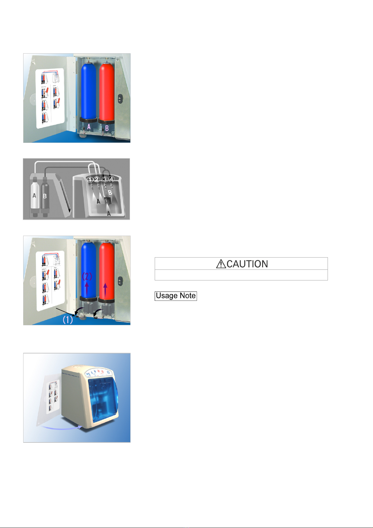
(6) Spray Cans
1. Open the side door.
Press the spot indicated in the photo to open the door.
2. Set the stands for the cans in place as shown in the photo.
Tray Filte
r
Tray
Side Doo
r
Press
Operation 2017-12-27 14
3. Can A is for the chuck maintenance and handpiece nozzles
1 and 2. Can B is for nozzles 3 and 4.
4. Push the lock levers down to a horizontal position to secure
the cans.
Oil will leak or spray out if the cans are not properly installed.
♦Make sure the lock levers are all the way down.
Otherwise, the oil will not come out. (The empty lamp will
start blinking.)
♦Pull and push the cans to make sure they are secure and do
not wobble.
5. Close the side door.
Lock Leve
r
Operation 2013-07-08
15
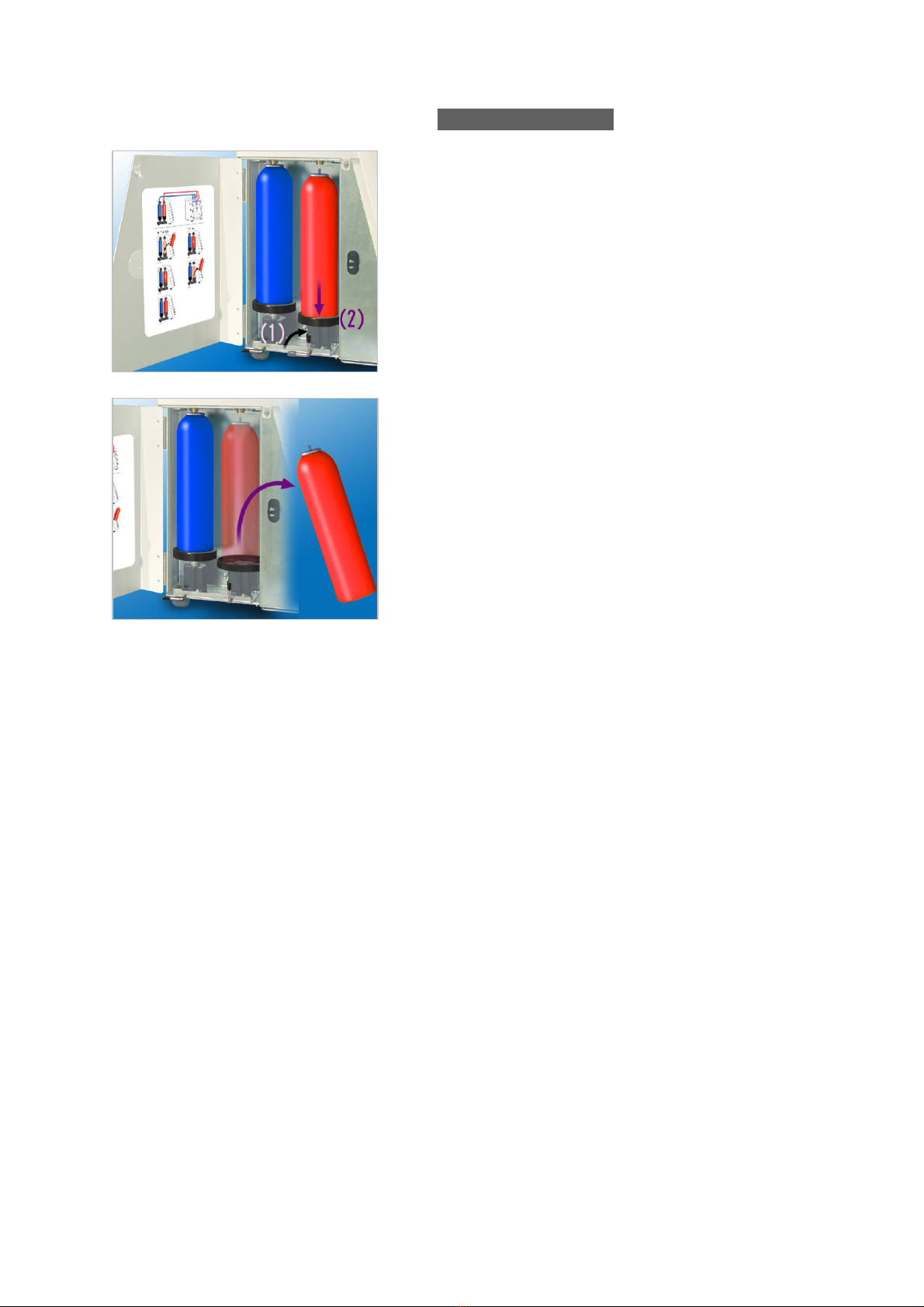
(7) Spray Can Removal
1. Pull the lock lever straight up to lower the stand.
2. Take the can out.
If the can’s nozzle is stuck in place, simply pull it down
slightly and take it out.

Operation 2017-12-27 16
5. Operation
Handpiece Autoclave Sterilization
To prevent the spread of grave, life-threatening diseases like HIV and hepatitis B, autoclave handpieces after
performing regular maintenance using LUBRICARE.
<Take Off>
<Clean>
(1) Take the handpiece off its tube.
(Remove the burr as well.)
(2) Clean the head with a brush and running water.
(3) Wipe the handpiece with gauze dampened with Ethanol
for Disinfection (Ethanol 70 to 80 vol%).
LUBRICARE Procedure
< Clean and Lubricate >
Perform chuck maintenance for Morita ball bearing
handpieces.
Perform the maintenance procedure.
<Clean>
Remove excess oil by wiping with Ethanol for Disinfection
(Ethanol 70 to 80 vol%).
<Autoclave> Autoclave in a sterilization pouch.
♦Some oil may remain inside the handpiece even after autoclaving. Refer to the user instructions for each
handpiece for proper storage. (Storing the handpiece in an upright position is recommended.)

Operation 2017-12-27
17
* If LUBRICARE hasn’t been used for a while, make sure it
operates properly and safely before using it.
Avoid the risks of electrical shock, equipment damage and
fire during an electrical storm: Turn LUBRICARE off
and do not touch it or its cord.
Wear surgical gloves to operate and clean LUBRICARE.
<Set Up>
• Carefully clean off the outside of the handpiece before
performing maintenance.
• Remove the burr.
Chuck Cleaning and Lubrication
Turn the main switch on.
(Green power lamp lights up.)
Open the front door.
Front doo
r
Power Lamp
Operation 2017-12-27 18
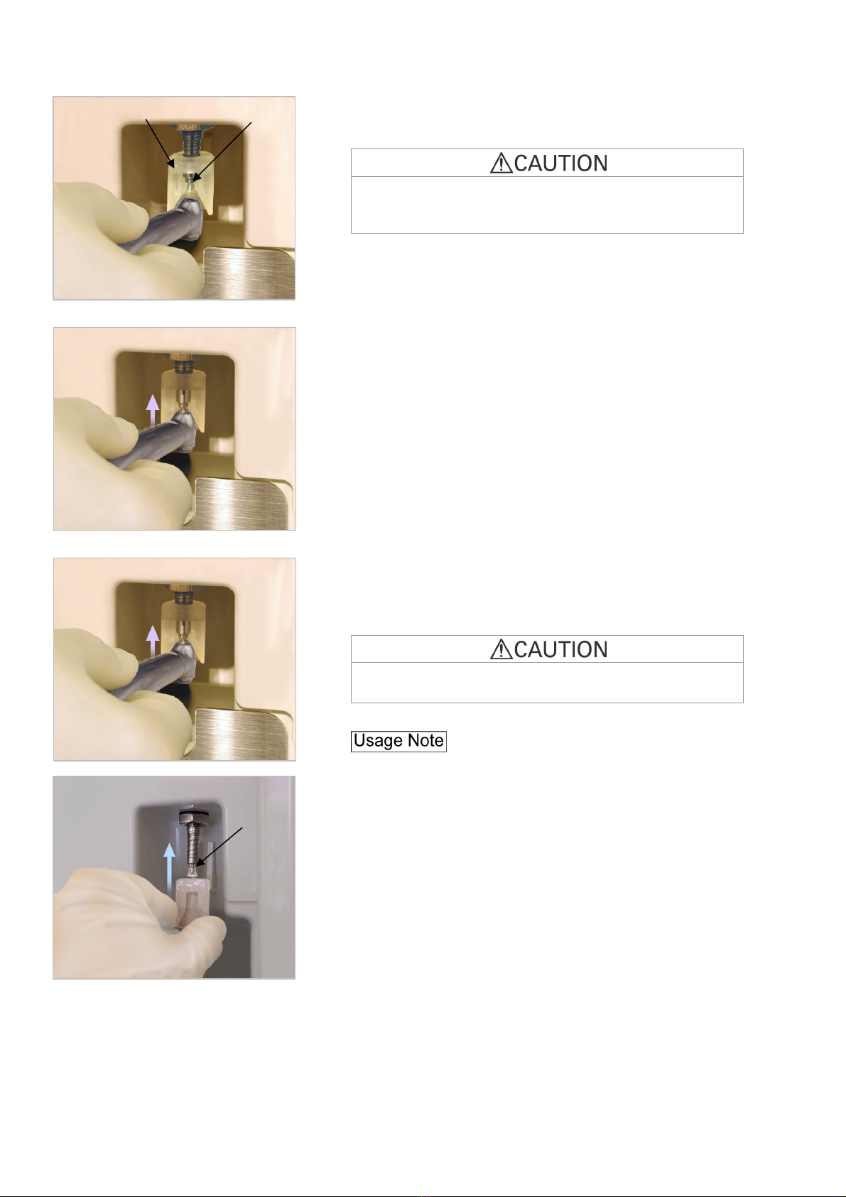
Line up the front end of the head with the nozzle guide and set
the chuck in place.
Make sure the head is flat against the nozzle guide. If it is
tilted, the nozzle might be bent or oil might spray out into your
eyes.
Lift the handpiece up slightly to begin cleaning and
lubricating the chuck.
Hold it in place for about 5 seconds.
A beep sounds when the procedure is finished.
* A series of beeps signals an error. In this case, try again.
Oil will spray out of the nozzle if the handpiece is removed too
soon (before the beep).
♦Chuck cleaning and lubrication is only for Bien-Air
handpieces.
♦If the nozzle guide comes off, line up the tab on it with the
groove and slide it back on.
Nozzle Guide Chuck Nozzle
Groove
Hold
Table of contents
Other Bien Air Medical Equipment manuals


