Bien Air CHIROPRO L User manual
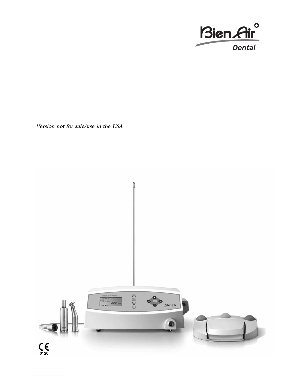
CHIROPRO L / CHIROPRO
ENG Instructions for use
0120
REF 2100219-0003/2014.05ENG
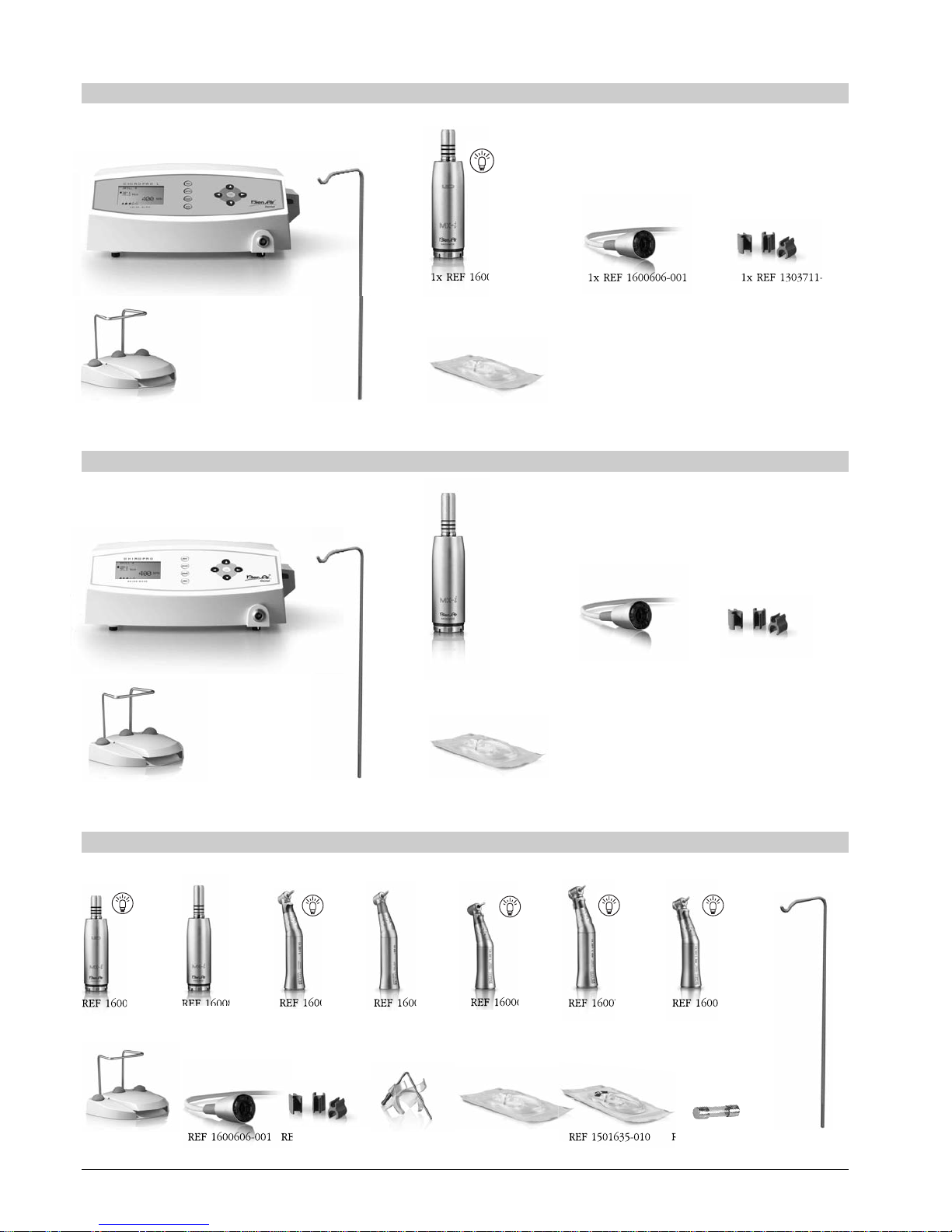
Set CHIROPRO L REF 1700298-001
Options
1x REF 1600613-001
1x REF 1500984-010
1x REF 1600631-001 1x REF 1303393-001
REF 1600598-001 REF 1600632-001
1x REF 1600755-001 1x REF 1600606-001 1x REF 1303711-010
10x
1x REF 1600631-001
REF 1600755-001 REF 1600825-001
REF 1600631-001
CA 20:1 L CA 20:1
REF 1600692-001
CA 20:1 L
Micro-Series
10x
1x REF 1500984-010
1x REF 1303393-001
10x
10x
Set CHIROPRO REF 1700387-001
1x REF 1600724-001
REF 1301560-010
10x
10x
REF 1500984-010
REF 1303711-010
REF 1600606-001
10x
REF 1600785-001 REF 1600786-001
CA 20:1 L KM CA 20:1 L KM
Micro-Series
REF 1303393-001
10x
REF 1501621-010 REF 1501635-010
1x REF 1600825-001 1x REF 1600606-001 1x REF 1303711-010
10x

CHIROPRO L / CHIROPRO

Summary
Starting display
Starting display
Availa le values
Availa le values
Implantology
Implantology
Endodontics
urgery
Round bur 1
Round bur 1
Round bur 2
Round bur 2
Drill 1
Drill 1
Drill 2
Drill 2
Drill 3
Drill 3
Drill 4
Drill 4
Tapping
Tapping
Tap unscrewing
Tap unscrewing
Implant screwing
Implant screwing
Unscrewing
Unscrewing
100 - 40’000 rpm
100 - 40’000 rpm
with a CA 1 : 1
with a CA 1 : 1
Depends on the CA
Depends on the CA
0.48 - 4.8 Ncm
0.48 - 4.8 Ncm
with a CA 1 : 1
with a CA 1 : 1
Depends on the CA
Depends on the CA
30 ml/min 20%
30 ml/min 20%
60 ml/min 40%
60 ml/min 40%
90 ml/min 60%
90 ml/min 60%
120 ml/min 80%
120 ml/min 80%
150 ml/min 100%
150 ml/min 100%
Implantology
Endodontics
urgery
Open pulp chamber
endo file 1
endo file 2
endo file 3
endo file 4
endo file 5
endo file 6
endo file 7
endo file 8
endo file 9
128:1
128:1
64:1
64:1
30:1
30:1
27:1
27:1
20:1
20:1
16:1
16:1
10:1
10:1
1:1
1:1
1:2
1:2
1:5
1:5
128:1
64:1
30:1
27:1
20:1
16:1
10:1
1:1
1:2
1:5
128:1
64:1
30:1
27:1
20:1
16:1
10:1
1:1
1:2
1:5
100 - 40’000 rpm
with a CA 1 : 1
Depends on the CA
0.48 - 4.8 Ncm
with a CA 1 : 1
Depends on the CA
30 ml/min 20%
60 ml/min 40%
90 ml/min 60%
120 ml/min 80%
150 ml/min 100%
Implantology
Endodontics
urgery
Apical resection
Tooth extraction
inus lift
Free
100 - 40’000 rpm
with a CA 1 : 1
Depends on the CA
0.48 - 4.8 Ncm
with a CA 1 : 1
Depends on the CA
30 ml/min 20%
60 ml/min 40%
90 ml/min 60%
120 ml/min 80%
150 ml/min 100%
MAIN MENU
IMPLANT SYST.
Steps
Steps
Ratio
Ratio
Speed in rpm
Speed in rpm
Torque in Ncm
Torque in Ncm
Irrigation
in ml/min
Irrigation
in ml/min
CHIROPRO L
CHIROPRO
traumann
Nobel Biocare
Zimmer
Dentsply Friadent
Biomet 3i
Astra Tech
Thommen Medical
ystème

33
ENG
1
1 Symbols Page
Meaning of symbols 34
2
2 Description
Identification 35
Intended use 35
Environment 35
Environmental protection and information for disposal of the instrument 35
3
3 Set supplied 36
4
4 Options 36
5
5 Technical description
Technical data 37
Electromagnetic compatibility 38-39
6
6 Installation 40-41
7
7 Description of keys and elements 42
8
8 Operation
escription of functions 43
Start-up 44
Pre-settings (SETUP) 44-45
escription of programs 46
- Implantology
- Endodontics*
- Surgery*
9
9 List of errors / Troubleshooting 47
10
10 Default values
Implantology 48+129
Endodontics*48+130
Surgery*48+130
11
11 Maintenance
Servicing 48
Information 48
Cleaning-disinfection 48
Important 48
12
12 Generalities and guarantee
General information 48
Terms of guarantee 48
Contenu
Table of contents
*only CHIROPRO L
34
ENG
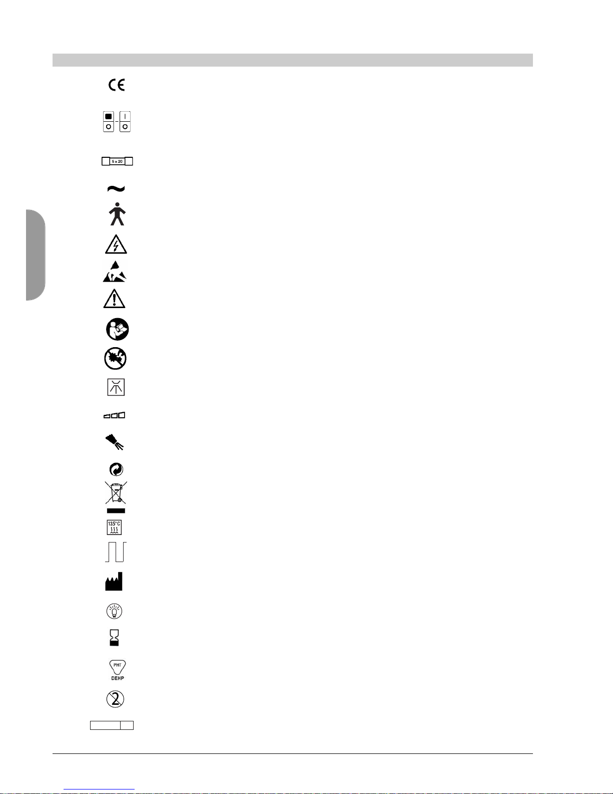
CE Marking with number of the notified body.
Main switch
ON - The instrument is switched on.
OFF - The instrument is switched off.
Fuse Ø 5 x 20 mm.
Alternating current.
evice of type B.
CAUTION ! angerous voltage.
Element sensitive to electrostatic discharges.
Warning.
CAUTION! Refer to the accompanying documents.
anger of pinching. o not put your fingers in rotating parts.
Machine washable.
Variability in steps.
Symbol for “Water-cooling”.
Recyclable materials.
Recyclable electrical and electronic materials.
Sterilisable in autoclave up to the specified temperature.
Operating mode intermittent.
Manufacturer.
Light.
Expiration date.
Product containing phthalates.
isposable product.
Sterilise with Ethylene Oxyde
0120
STERILE EO
1
1 Meaning of symbols

35
ENG
*only CHIROPRO L
2
2 Description
Electronically controlled tabletop device for dentistry allowing operation of an MX-i LE /MX-i micro-
motor with variable speed control by a pedal.
A peristaltic pump conveys the physiological liquid via a disposable irrigation line without being
contaminated.
The device's LC display indicates the stage of implant fitting, the instrument's ratio, the bur speed,
torque value and irrigation flow setting.
The system is to be used by dentists and surgeons in dental offices and hospitals. The system is des-
igned to control a dental micromotor which can drive a dental hand-piece fitted with appropriate tools
to cut hard and soft tissues in the mouth and to screw dental implants.
The system is intended for use in dentistry for implantology, dental surgery* and endodontic* work.
Any use other than that for which this product is intended is unauthorised and may be dangerous.
The medical device meets all the current legal requirements.
The device is not designed for use in an explosive atmosphere (anaesthetic gas).
Working Temperature: +10°C (50°F) to +25°C (77°F)
Relative humidity: 30% to 80%, including condensation
Atmospheric pressure: 700 hPa to 1060 hPa
Transport Environmental conditions
and storage Temperature: -25°C (-13°F) to +70°C (158°F)
Relative humidity: 10% to 100%, including condensation
Atmospheric pressure: 500 hPa to 1060 hPa
The disposal and/or recycling of materials must be performed in accordance with the legislation
in force.
This device and its accessories must be recycled.
Electrical and electronic equipment may contain dangerous substances which constitute health and
environmental hazards. The user must return the device to its dealer or establish direct contact with an
approved body for treatment and recovery of this type of equipment (European irective 2002/96/EC).
Identification
Environment
Environmental
protection and infor-
mation for disposal
of the instrument
Intended use

36
ENG
3
3 Set supplied
4
4 Options
Contra-angle handpiece CA 20:1 L (light) REF 1600598-001
Contra-angle handpiece CA 20:1 L Micro-Series (light) REF 1600692-001
Contra-angle handpiece CA 20:1 L KM (light) REF 1600785-001
Contra-angle handpiece CA 20:1 L KM Micro-Series (light) REF 1600786-001
MX-i LE micromotor REF 1600755-001
MX-i micromotor REF 1600825-001
Cable for MX-i LE micromotor REF 1600606-001
Pedal 3 buttons REF 1600631-001
Pack of 10 disposable sterile lines REF 1500984-010
Kirschner/Meyer type detachable irrigation set for CA 20:1 L KM and
CA 20:1 L KM Micro-Series, comprising 10 rings and 10 tubes REF 1501621-010
Kirschner/Meyer pack of 10 disposable sterile lines REF 1501635-010
10 attachments collars for fastening the sterile irrigation line to a cable REF 1303711-010
Bracket for fluid bottle REF 1303393-001
Support REF 1301575-001
Cable system 3P, Switzerland, length 2.00 m REF 1300065-001
Cable system 3P, Europe, length 2.50 m REF 1300066-001
Cable system 3P, US / Asia, length 2.00 m REF 1300067-001
10x Fuse T4.0A L 250 VAC breaking capacity 40A REF 1301560-010
1x CHIROPRO L control REF 1600613-001
1x Micromotor MX-i LE REF 1600755-001
1x Cable for MX-i LE micromotor REF 1600606-001
1x Pack of 10 disposable sterile lines REF 1500984-010
1x 10 attachment collars for fastening the sterile irrigation line to a cable REF 1303711-010
1x Bracket for fluid bottle REF 1303393-001
1x Pedal 3 buttons REF 1600631-001
1x Cable system 3P, Switzerland, length 2.00 m REF 1300065-001
1x Cable system 3P, Europe, length 2.50 m REF 1300066-001
1x Cable system 3P, US/Asia, length 2.00 m REF 1300067-001
1x Instructions REF 2100219
1x CHIROPRO control REF 1600724-001
1x Micromotor MX-i REF 1600825-001
1x Cable for micromotor MX-i REF 1600606-001
1x Pack of 10 disposable sterile lines REF 1500984-010
1x 10 attachment collars for fastening the sterile irrigation line to a cable REF 1303711-010
1x Bracket for fluid bottle REF 1303393-001
1x Pedal 3 buttons REF 1600631-001
1x Cable system 3P, Switzerland, length 2.00 m REF 1300065-001
1x Cable system 3P, Europe, length 2.50 m REF 1300066-001
1x Cable system 3P, US/Asia, length 2.00 m REF 1300067-001
1x Instructions REF 2100219
Set CHIROPRO L
REF 1700298-001
Set CHIROPRO
REF 1700387-001

37
ENG
*only CHIROPRO L
5
5 Technical Description: Technical data
Voltage
100 – 240 VAC
50 – 60 Hz
Fuses
2 fuses T4.0A L 250 VAC, breaking capacity 40A
Power demand
- 100 V /300 VA
- 240 V /300 VA
Classification
Class IIa in accordance with European irective 93/42/EEC
concerning medical devices.
Electric insulation class
Class I, per IEC 60601-1
(apparatus protected against electric shocks).
Degree of protection
IP 40 (protection against insertion of objects larger than
1 mm).
Dimensions L x W x H
309 x 220 x 123 mm. Height with bracket 506 mm
Weight
Housing 2.7 kg Pedal 830 g
Cable 105 g Bracket 115 g
Memory
Implantology mode: Storage in memory of 8 implant fitting
sequences of 10 steps each.
Endodontics*mode: Storage in memory of an endodontics
sequence of 10 steps.
Surgery*mode: Storage in memory of 4 separate
programs.
Languages
French, German, English, Italian, Spanish, Portuguese,
Japanese and Russian.
List of errors & Troubleshooting
Page 47
Bracket for physiological liquid flask
Stainless steel
Intended for use with: see instructions
Micromotor MX-i LE REF 2100245
Micromotor MX-i REF 2100245
Cable for micromotor REF 2100163
Contra-angle CA 20:1, without light REF 2100209
Contra-angle CA 20:1 L, with light REF 2100209
Contra-angle CA 20:1 L Micro-Series, with light REF 2100209
Contra-angle CA 20:1 L KM, light REF 2100209
Contra-angle CA 20:1 L KM Micro-Series, light
REF 2100209
The use of the system with other handpieces, motors
or cables has not been validated/certified
Peristaltic pump
Pump delivery: From 30 to 150 ml/min. (5 levels).
Hose for pump: External Ø 5.60 mm,
internal Ø 2.40 mm
Wall thickness 1.60 mm.
Pedal
REF 1600631-001
imensions (LxWxH) 250 x 205 x 54 mm
with handle: 250 x 205 x 144 mm
The pedal is waterproof (IP X8 in accordance with CEI 529).
Cables
Length of cables:
Pedal cable 2.90 m
Motor cable 2.00 m
WARNING
To prevent any risk of electric shock, this device must be
connected only to a power supply network provided with
protective earth.
Modification of the device forbidden.
The system is not adapted to be used in the presence of
inflammable gases (e.g. anaesthetic gas).
o not attempt to open the apparatus when it is connected
to the electric mains. Beware of electric shocks.
Applied parts (per IEC 60601-1)
MX-i LE micromotor REF 1600755-001
MX-i Micromotor REF 1600825-001
Cable for micromotor MX-i LE REF 1600606-001
CA 20:1 L REF 1600598-001
CA 20:1 REF 1600632-001
CA 20:1 L Micro-Series REF 1600692-001
CA 20:1 L KM REF 1600785-001
CA 20:1 L KM Micro-Series REF 1600786-001
Irrigation lines REF 1500984-010
KM Irrigation lines REF 1501635-010
KM detachable Irrigation set REF 1501621-010
Operating mode:
Intermittent
ON: 5 min.
OFF: 40 min.

38
ENG
5
5 Technical Description: Electromagnetic compatibility
Electro-medical equipment needs special precautions regarding EMC and needs to be installed and put
into service according to the EMC information provided in this document.
CHIROPRO L/CHIROPRO complies with the EMC requirements according to IEC 60601-1-2. Radio trans-
mitting equipment, cellular phones, etc. shall not be used in close proximity of the device since they
could influence the performance of the device. Particular precaution is required when using strong emis-
sion sources such as High Frequency surgical equipment and similar equipment so that the HF cables
are not routed on or near the device. If in doubt, please contact a qualified technician or Bien-Air ental.
CHIROPRO L/CHIROPRO should not be used adjacent or stacked with other equipment. If adjacent or
stacked use is necessary, CHIROPRO L/CHIROPRO should be monitored to verify normal operation in
the configuration in which it will be used.
Precautions regar-
ding Electromagnetic
Compatibility (EMC)
The use of accessories, transducers and ca-bles other than those specified, with the exception
of transducers and cables sold by Bien-Air Dental as replacements parts for internal compo-
nents, may result in increased emissions or decreased immunity of CHIROPRO L/CHIROPRO.
Dental professionals need to be aware of potential electromagnetic interference between elec-
tronic dental devices and active implantable medical devices, and should always inquire about
any devices implanted in the patient.
WARNING!
CHIROPRO L/CHIROPRO is intended for use in the electromagnetic environment specified below.
The customer or the user of CHIROPRO L/CHIROPRO should ensure that it is used in such an envi-
ronment.
Guidance and manu-
facturer’s declaration
- electromagnetic
emissions
Emissions test Compliance Electromagnetic environment - guidance
RF emissions Group 1 CHIROPRO L/CHIROPRO uses RF energy only for its internal function.
CISPR 11 Therefore, its RF emissions are very low and are not likely
to cause any interference in nearby electronic equipment.
RF emissions Class B
CISPR 11 CHIROPRO L/CHIROPRO is suitable for use in all Establishments,
including domestic establishments and those directly connected
Harmonic emissions Not applicable to the public low-voltage power supply network that supplies
IEC 61000-3-2 buildings used for domestic purposes.
Voltage fluctuations/flicker emissions
IEC 61000-3-3 Compliant
Guidance and manufacturer’s declaration - electromagnetic immunity
CHIROPRO L/CHIROPRO is intended for use in the electromagnetic environment specified below.
The customer or the user of CHIROPRO L/CHIROPRO should ensure that it is used in such an environment.
Immunity test IEC 60601 test level Compliance level Electromagnetic environment - guidance
Electrostatic ±6 kV contact ±6 kV contact
discharge (ES )
±8 kV air ±8 kV air
IEC 61000-4-2
Electrical fast ±2 kV for power ±2 kV for power
transient burst supply lines supply lines
IEC 61000-4-4 ±1 kV for lines no ±1 kV for lines no
input/output input/output
Shock waves ±0.5 kV line to line ±0.5 kV line to line
IEC 61000-4-5 ±1 kV line to line ±1 kV line to line
±0.5 kV line to earth ±0.5 kV line to earth
±1 kV line to earth ±1 kV line to earth
±2 kV line to earth ±2 kV line to earth
Voltage dips <5% UT<5% UT
and outages (>95% dip in UT) (>95% dip in UT)
for 0.5 cycle for 0.5 cycle
40% UT40% UT
(60% dip in UT) (60% dip in UT)
for 5 cycles for 5 cycles
70% UT70% UT
IEC 61000-4-11 (30% dip in UT) (30% dip in UT)
for 25 cycles for 25 cycles
<5% UT<5% UT
(>95% dip in UT) (>95% dip in UT)
for 5 sec for 5 sec
Power frequency
(50/60 Hz) 3 A/m 3 A/m
magnetic field
IEC 61000-4-8
NOTE UTis the a.c. mains voltage prior to application of the test level.
Essential performance: The essential performance is the maintaining of the visual lighting intensity of the LE and the maintaining of motor
speed. Maximum allowed speed deviation is ± 5%.
Floors should be wood, concrete or ceramic tile. If floors
are covered with synthetic material, the relative humidity
should be at least 30%.
Mains power quality should be that of a typical commer-
cial or hospital environment.
Mains power quality should be that of a typical commer-
cial or hospital environment.
Mains power quality should be that of a typical commer-
cial or hospital environment. If the user of CHIROPRO L/
CHIROPRO requires continued operation during power
mains interruptions, it is recommended that CHIROPRO L/
CHIROPRO be powered from an uninterruptible power
supply or a battery.
Power frequency magnetic fields should be at levels
characteristic of a typical location in a typical commercial
or hospital environment.

39
ENG
5
5 Technical Description: Electromagnetic compatibility
Portable and mobile RF communications equipment should be used no closer
to any part of CHIROPRO L/CHIROPRO, including cables, than the recom-
mended separation distance calculated from the equation applicable to the
frequency of the transmitter.
Recommended separation distance
80 MHz to 800 MHz
800 MHz to 2.5 GHz
where Pis the maximum output power rating of the transmitter in watts (W)
according to the transmitter manufacturer and dis the recommended separa-
tion distance in metres (m).
Field strengths from fixed RF transmitters, as determined by an electromagnet-
ic site survey,ashould be less than the compliance level in each frequency
range.b
Interference may occur in the vicinity of equipment marked with the following
symbol:
Guidance and manufacturer’s declaration - electromagnetic immunity
CHIROPRO L/CHIROPRO is intended for use in the electromagnetic environment specified below.
The customer or the user of CHIROPRO L/CHIROPRO should ensure that it is used in such an environment.
Immunity test IEC 60601 Compliance Electromagnetic environment - guidance
test level level
Conducted RF 3 Vrms 3 V
IEC 61000-4-6 150 kHz to 80 MHz
Radiated RF 3 V/m 3 V/m
IEC 61000-4-3 80 MHz to 2,5 GHz
NOTE 1 At 80 MHz and 800 MHz, the higher frequency range applies.
NOTE 2 These guidelines may not apply in all situations. Electromagnetic propagation is affected by absorption and reflection from structures,
objects and people.
aField strengths from fixed transmitters, such as base stations for radio (cellular/cordless) telephones and land mobile radios, amateur radio,
AM and FM radio broadcast and TV broadcast cannot be predicted theoretically with accuracy. To assess the electromagnetic environment
due to fixed RF transmitters, an electromagnetic site survey should be considered. If the measured field strength in the location in which the
CHIROPRO L/CHIROPRO is used exceeds the applicable RF compliance level above, the CHIROPRO L/CHIROPRO should be observed to
verify normal operation. If abnormal performance is observed, additional measures may be necessary, such as reorienting or relocating the
CHIROPRO L/CHIROPRO.
bOver the frequency range 150 kHz to 80 MHz, field strengths should be less than 3 V/m.
Recommended separation distances between portable and mobile RF communications equipment and the
CHIROPRO L/CHIROPRO
The CHIROPRO L/CHIROPRO is intended for use in an electromagnetic environment in which radiated RF disturbances are controlled. The custo-
mer or the user of the CHIROPRO L/CHIROPRO can help prevent electromagnetic interference by maintaining a minimum distance between por-
table and mobile RF communications equipment (transmitters) and the CHIROPRO L/CHIROPRO as recommended below, according to the maxi-
mum output power of the communications equipment.
Rated maximum output Separation distance according to frequency of transmitter
power of transmitter m
W150 kHz to 80 MHz 80 MHz to 800 MHz 800 MHz to 2.5 GHz
0.01 0.12 0.12 0.23
0.1 0.38 0.38 0.73
1 1.2 1.2 2.3
10 3.8 3.8 7.3
100 12 12 23
For transmitters rated at a maximum output power not listed above, the recommended separation distance din metres (m) can be estimated
using the equation applicable to the frequency of the transmitter, where Pis the maximum output power rating of the transmitter in watts (W)
according to the transmitter manufacturer.
NOTE 1 At 80 MHz and 800 MHz, the separation distance for the higher frequency range applies.
NOTE 2 These guidelines may not apply in all situations. Electromagnetic propagation is affected by absorption and reflection from structures,
objects and people.
40
ENG
6
6 Installation
Installation
A. CHIROPRO L/CHIROPRO may be positioned on a table, on a trolley or
another surface, but in no circumstances on the floor.
Power plug is the device for disconnection in case of problems,
and it must be easily accessible at all times.
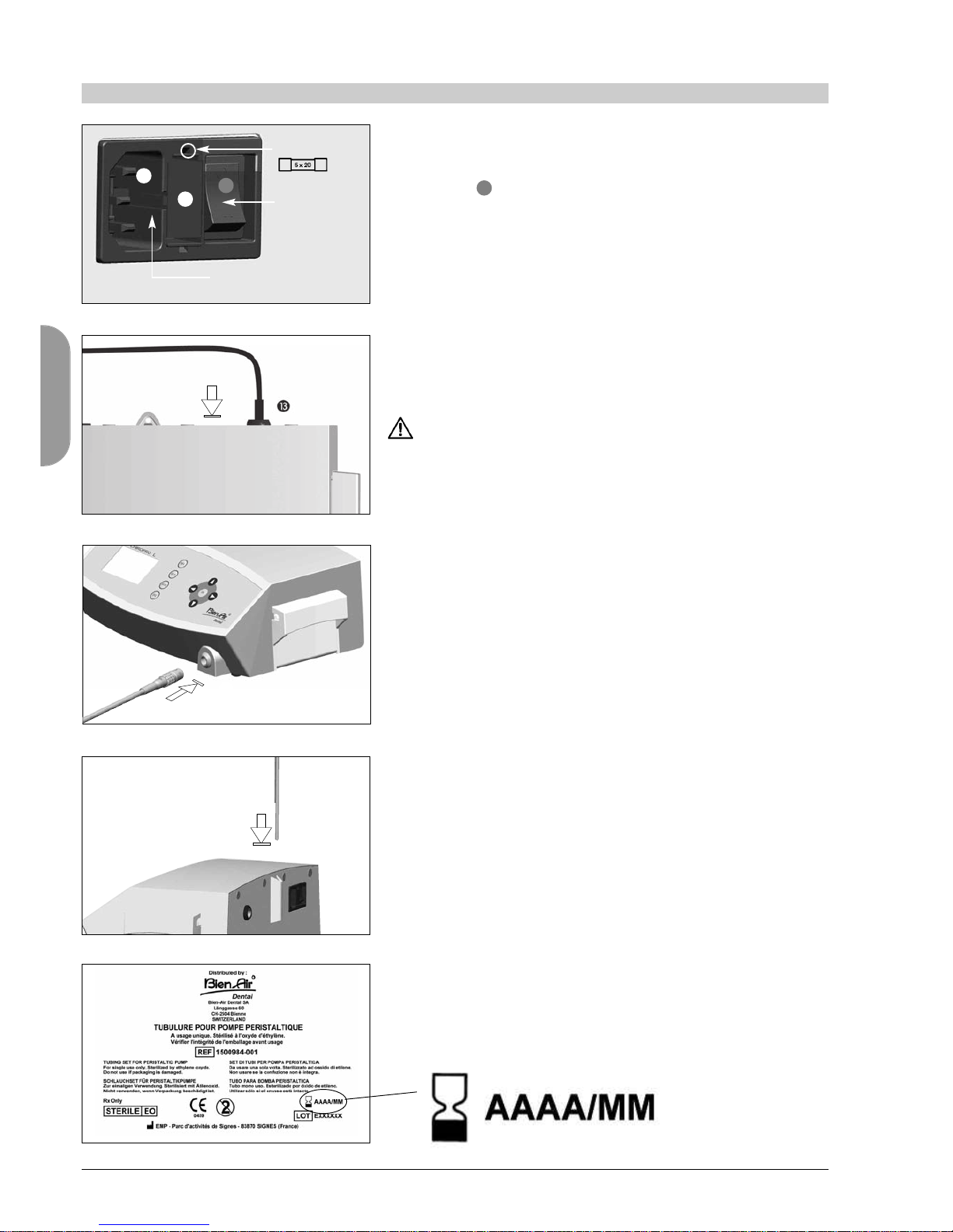
B. The fuse box may be opened with a screwdriver.
100 - 240 Vac = fuse T-4.0 A L 250 VAC REF 1301560-010
C. The equipment is powered by your line voltage (100/115/230 Vac).
Connect the power cable to the plug fig. 1.
. Connect the pedal cable to the output provided on the rear panel,
guiding the connector and plug by means of the index pin on the
connector fig. 2.
o not raise the pedal using the connection cable.
E. Connect the micromotor cable to the motor output, guiding the
connector and plug by means of the index pin on the connector fig. 3.
F. Align and attach the bracket to the housing provided on the console’s
rear and suspend the flask or bottle fig. 4.
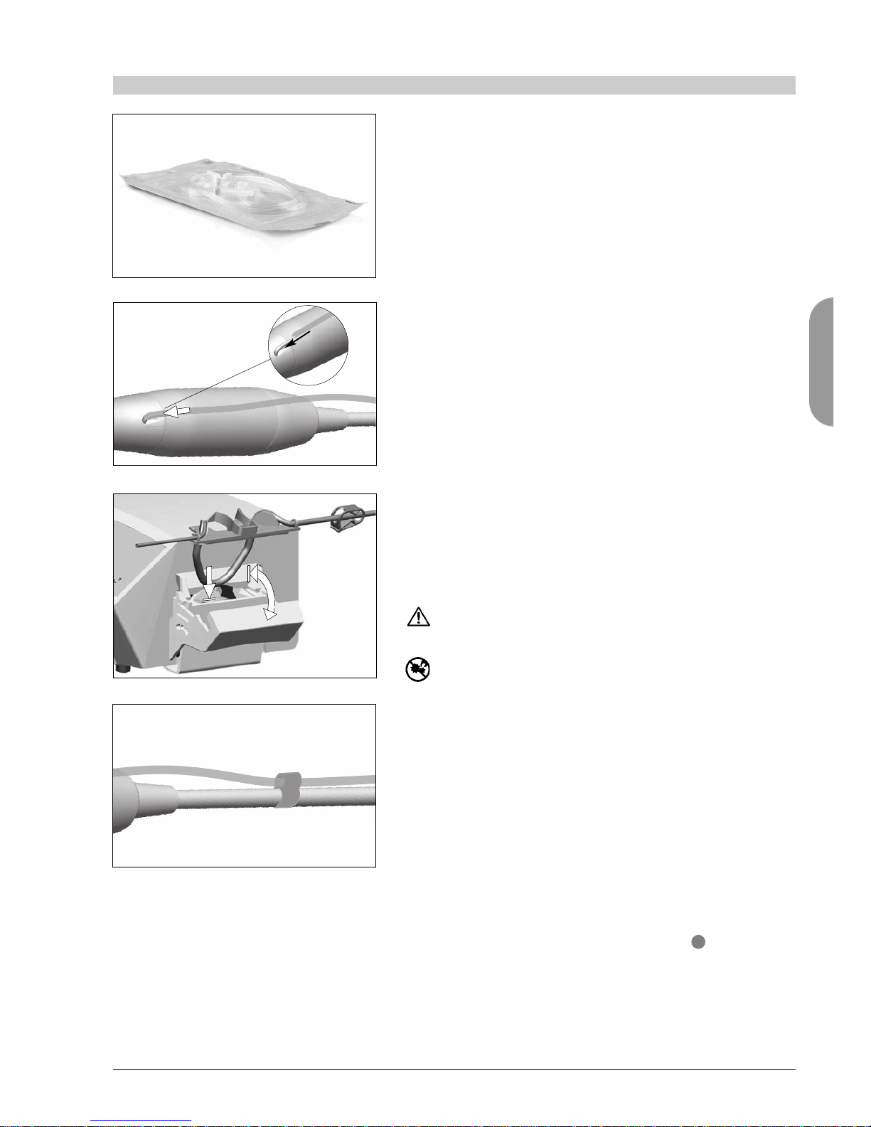
G. Check the packaging integrity, as well as the expiry date of the irrigation
line.
Only lines supplied by Bien-Air ental ensure trouble-free operation.
These lines are sterile and for single use. Re-use may result in microbio-
logical contamination of the patient.
Fuse
fig. 1
fig. 2
fig. 3
fig. 4
fig. 5
ON/OFF
Plug
=
>
16 14
7
41
ENG
6
6 Installation
fig. 8
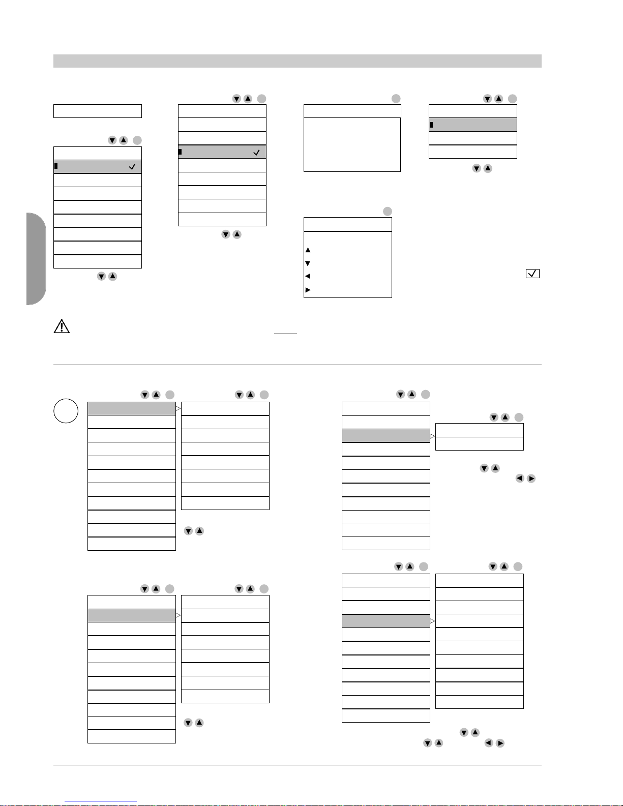
H. Remove the single-use sterile irrigation line from its pouch.
Fitting on the spray tube
I. Connect the flexible hose of the irrigation line to the spray tube of the
handpiece or contra-angle fig. 7.
Installation on the peristaltic pump
J. Install the plastic cassette in the peristaltic pump.
Check that the cassette is clipped correctly.
Close the pump lid, fig. 8.
If there is resistance to closing, open the lid again and check the correct
positioning of the cassette.
Warning!
Do not run the pump while the lid is open.
Danger of pinching!
K. Perforate the cap of the physiological liquid flask with the pointed end
of the irrigation line after removing the protective cap.
L. Attach the irrigation line on the motor cable using the attachment collars
REF 1303711-010 fig. 9.
The device can be safely stopped using the main switch .
fig. 6
fig. 7
fig. 9
REF 1303711-010
16
Stopping procedure

42
ENG
*only CHIROPRO L
7
7 Description of keys and elements
0DEVICE SCREEN
1COMMAND TO REVERSE THE ROTATION OF
THE MICROMOTOR
2“SETUP” MENU CALL-UP EY
3PARAMETERS BAC UP EY
4RETURN EY
uCOMMANDS DEVICE
own key
Up key
Left key (–)
Right key (+)
Confirmation/selection key
In implantology/endodontics*mode: next stage
6PERISTALTIC PUMP LID
7MICROMOTOR CONNECTOR
8IRRIGATION ON/OFF CONTROL BUTTON
ON PEDAL
9“PROGRAM” BUTTON ON PEDAL
In implantology/endodontics*mode:
- Short press: next stage
- Long press: previous stage
:BUTTON TO REVERSE THE ROTATION
OF THE MICROMOTOR ON PEDAL
;VARIABLE SPEED DRIVE ON PEDAL
<PEDAL CONNECTOR
=MAINS CONNECTOR (100/115/230 VAC)
>FUSE HOLDER
?MAIN SWITCH ON THE DEVICE
@LABEL
ABRAC ET SUPPORT
BMICROMOTOR
Selection cursor
Instrument transmission ratio
Torque setting
Speed adjustment
Adjusting irrigation
ROUND BUR
20:1
28.0 Ncm
1’000
Name of program
Reversal of motor rotation symbol
Motor overheating
Irrigation stopped
Only in SETUP mode
Activation/deactivation of the
stage
OK }}cursor
adjusting
RPM

43
ENG
*only CHIROPRO L
8
8 Operation
The "reverse" function can be chosen directly in all the programs except endodontics*.
Upon selection, a beep and the "reversal of motor rotation" icon indicate reverse rotation.
For endodontics*, settings must be performed under SETUP (Auto-forward/Auto-reverse).
See next page.
Stores the settings of a program: press the key until a beep is emitted, and the values that are flashing
will be stored in the memory directly.
Return function. With "ESC", you can leave the current screen. In “Implantology” and “Endodontics*”
mode, can also be used to return to the previous stage.
If the name of the program flashes when exiting, the changes will not be taken into consideration.
The changes must always be confirmed with "SAVE", otherwise they will be lost.
BLUE
Activation/ eactivation
of the peristaltic pump.
GREY
Activation/ eactivation of reversal
of motor rotation.
ORANGE
Program key:
- Short press next stage
- Long press previous stage
ESC
SETUP
REV
SAVE
Description of functions
CHIROPRO L
Motor speed control pedal.
1
2
3
4
1
2
3
4
44
ENG
*only CHIROPRO L
8
8 Operation
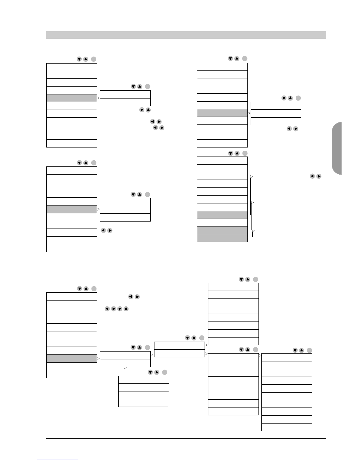
SETUP
Pre-settings
Start-up
Implant. system
Language
Endo*system
Ratio
Light
Footpedal
Torque units
Contrast
Editor Editor
Editor
Editor
System info
Restore defaults
English
1.
2.
3. 4.
OK: continue
ESC: back
5.
OK: continue
*6.
with
OK: go directly to pre-setting
with no possibility of deactiva-
ting the stages
or
with SETUP, possibility of de-
activating the stages with
Français
Deutsch
Italiano
Español
Português
Russian
apanese
Implant. system
Language
Endo*system
Ratio
Light
Footpedal
Torque units
Contrast
System info
Restore defaults
Straumann
Nobel Biocare
Zimmer
Dentsply Friadent
Biomet 3i
Astra Tech
Thommen Medical
System
Implant. system
Language
Endo*system
Ratio
Light
Footpedal
Torque units
Contrast
System info
Restore defaults
Endo steps
Endo parameters
Implant. system
Language
Endo*system
Ratio
Light
Footpedal
Torque units
Contrast
System info
Restore defaults
128:1
64:1
30:1
27:1
20:1
16:1
10:1
1:1
1:2
1:5
OK
OK
OK
OK
OK
OK
OK
OK OK
OK
OK
OK OK
System loading.......
English
Implantology
Please check the
pre-programmed
values before
inserting implant.
Straumann
LANGUAGE
INFORMATION
MAIN MENU
<Name of selected system>
IMPLANT. SYSTEM
Français
Key functions:
move cursor UP
move cursor DOWN
decrem./disable
increm./enable
Endodontics*Nobel Biocare
Deutsch
Surgery*Zimmer
Italiano
Dentsply Friaden
Espanol
Biomet 3i
Português
Astra Tech
Russian
Thommen Medical
apanese
System
All the pre-programmed settings are indicative and MUST be validated by the user.
This storing in memory takes place only at the first connection of the device and is subsequently maintained.
These parameters can then be modified in SETUP.
Select the language wanted
and confirm with OK.
Select the ratio to be changed OK, then
change of value with and with then
save with SAVE. Continue with OK. ESC: back
Select the system wanted
and confirm with OK.
ESC: change
Select with then OK.
If modifications with ,
the screen flashes.
save with SAVE continue
with OK.
Without modification,
continue with OK.
ESC: back
Select with
Confirmation with OK
Select with
Confirmation with OK
Select with
Confirmation with OK
45
ENG
*only CHIROPRO L
8
8 Operation
Pre-settings
Editor
Editor Editor
Editor
Implant. system
Language
Endo*system
Ratio
Light
Footpedal
Torque units
Contrast
System info
Restore defaults
Light OFF
Light ON
Implant. system
Language
Endo*system
Ratio
Light
Footpedal
Torque units
Contrast
System info
Restore defaults
Editor
Implant. system
Language
Endo*system
Ratio
Light
Footpedal
Torque units
Contrast
System info
Restore defaults
Implantology
Endodontics*
Surgery*
Implantology (Ncm)
Endodontics*(mNm)
Surgery*(Ncm)
Implant. system
Language
Endo*system
Ratio
Light
Footpedal
Torque units
Contrast
System info
Restore defaults
Implant. system
Language
Endo*system
Ratio
Light
Footpedal
Torque units
Contrast
System info
Restore defaults
OK
OK
OK
OK
OK
OK
OK
ON or OFF with then OK.
isplay under light ON:
Level: adjustment with
Time delay: setting with ,
save with SAVE, continue with OK.
ESC: back
ON/OFF or progressive with
, save with SAVE,
continue with OK.
ESC: back
Adjustable with , save with
SAVE, continue with OK.
ESC: back
Contrast adjustment with ,
save with SAVE, continue with
OK.
System Info:
software version, serial number
and electronics of the device.
Restore system:
Can be used to reinitialise
factory settings.
ROUND BUR 1
ROUND BUR 2
DRILL 1
DRILL 2
DRILL 3
DRILL 4
TAPPING
TAP UNSCREWING
IMPLANT SCREWING
UNSCREWING
Implantology (Ncm)
Surgery*(Ncm)
OK
OK System names
Tool names
OK
OK
Used to rename or customise the name of
the system, tool or treatment.
Select with then OK,choose the letters
on the keypad by moving the cursor using
then OK, save the new name
with SAVE, ESC: back
Apical resection
Tooth extraction
Sinus Lift
Free
OK
Straumann
Nobel Biocare
Zimmer
Dentsply Friadent
Biomet 3i
Astra Tech
Thommen Medical
System
OK
Straumann
Nobel Biocare
Zimmer
Dentsply Friadent
Biomet 3i
Astra Tech
Thommen Medical
System
OK

46
ENG
*only CHIROPRO L
8
8 Operation
Description of functions
Pre-programmed values, see pages 129-130
Implantology
Endodontics*
Surgery*
ROUND BUR 1
ROUND BUR 2
DRILL 1
DRILL 2
DRILL 3
DRILL 4
TAPPING
TAP UNSCREWING
IMPLANT SCREWING
UNSCREWING
100 - 40’000 rpm
with a CA 1:1
Depends on the
CA selected
0.48 - 4.8 Ncm
with a CA 1:1
Depends on the
CA selected
30 ml/min 20%
60 ml/min 40%
90 ml/min 60%
120 ml/min 80%
150 ml/min 100%
Implantology
Endodontics*
Surgery*
OPEN PULP CHAMBER
ENDO FILE 1
ENDO FILE 2
ENDO FILE 3
ENDO FILE 4
ENDO FILE 5
ENDO FILE 6
ENDO FILE 7
ENDO FILE 8
ENDO FILE 9
Implantology
Endodontics*
Surgery*
Apical resection
Tooth extraction
Sinus Lift
Free
MAIN MENU
Selection wanted
and confirm
with OK
Steps
Each of these stages
can be activated or
deactivated from the
SETUP menu.
See also info on the
last page.
OK: next step
ESC: previous step
Trans-
mission
ratio
Adjustable:
then SAVE
Speed
in rpm
Adjustable:
then SAVE
Torque
in Ncm
Adjustable:
then SAVE
Irrigation
in ml/min
Adjustable:
then SAVE
Select with the cursor
128:1
64:1
30:1
27:1
20:1
16:1
10:1
1:1
1:2
1:5
Selection cursor
Instrument transmission ratio
Torque setting
Speed adjustment
Adjusting irrigation
ROUND BUR
20:1
28.0 Ncm
1’000
Name of program
Reversal of motor rotation symbol
Motor overheating
Irrigation stopped
Only in SETUP mode
Activation/deactivation of the
stage
RPM
47
ENG
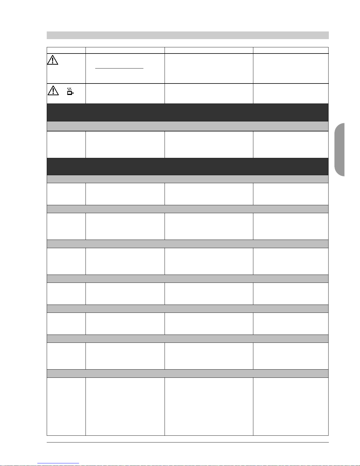
9
9 List of errors & Troubleshooting
Message
Release the
pedal
The pedal is pressed when starting
the device.
The motor is blocked for more
than 2 sec.
The motor control card limits the
power supplied to the motor to
prevent motor overheating.
Cause of error
Safety
Safety
Action
Release the pedal and press
again.
Avoid extended use.
Equipment initialisation error
The following error may occur at start-up of CHIROPRO L/CHIROPRO
1. Check on the integrity of the CHIROPRO L/CHIROPRO memory
INIT ERROR 1 The memory is corrupt!
Please contact Bien-Air ental SA.
ESC: restore
The memory data check failed. Press the ESC key to try to
restore the memory.
Contact Bien-Air ental SA.
Device operating error
The following errors may occur during operation of the device
1. Loss of pedal connection
ERROR 1 The pedal is not connected!
Please check the connection.
ESC: exit
The pedal is not connected correctly. Check pedal connection.
Contact Bien-Air ental SA.
2. Peristaltic pump overheating
ERROR 2 Irrigation pump overheating!
Please wait for it to cool.
ESC: exit
Peristaltic pump motor overheating Wait until the system cools.
Contact Bien-Air ental SA.
3. Peristaltic pump general error
ERROR 3 Irrigation pump fault!
Please contact Bien-Air ental SA.
ESC: exit
Peristaltic pump electrical fault. Contact Bien-Air ental SA.
4. Loss of motor connection
ERROR 4 The motor is not connected!
Please check the connection.
ESC: exit
Loss of motor phase fault.
The motor is not connected correctly.
Check motor connection.
Contact Bien-Air ental SA.
5. Motor cable fault
ERROR 5 Motor cable fault!
Please change cable.
ESC: exit
Motor power fault.
The motor cable may be defective.
Check motor cable.
Contact Bien-Air ental SA.
6. Motor control overheating
ERROR 6 System overheating!
Please wait for it to cool.
ESC: exit
Overheating of motor control card
(electrical control of motor).
Wait until the system cools.
Contact Bien-Air ental SA.
7. System electrical fault
GEN ERROR
[Error code]
System electrical fault!
Please contact Bien-Air ental SA.
ESC: exit
Communication fault with motor
control card: [EC100]
Motor control card power supply
undervoltage: [EC101]
Motor control card power supply
overvoltage: [EC102]
Other motor control card faults:
[EC120]
Contact Bien-Air ental SA.

48
ENG
*only CHIROPRO L
Implantology:
Default values page 129
The table shows the default operating values for the 8 implan-
tology systems pre-programmed in the system, namely:
• Straumann • Nobel Biocare • Zimmer • entsply Friadent
• Biomet 3i • Astra Tech • Thommen Medical • System,
available to the user (default settings identical to the
Straumann system).
Endodontics*: Default values page 130
The table shows the default operating values for the endodon-
tics sequence.
Surgery*: Default values page 130
The table shows the default operating values for 4 types of
surgical operations proposed by the system, namely: • Root
resection • Extraction of wisdom teeth • Sinus raising • Free
program, left available to the user.
10
10 Default values
Only use original Bien-Air ental maintenance products and
parts or those recommended by Bien-Air ental. Using other
products or parts may cause operational failure and/or void
the guarantee.
Servicing
Never disassemble the device. For any modification and repair,
we recommend that you contact your regular supplier or Bien-
Air ental directly. Bien-Air ental asks the user to have its
dynamic instruments checked or inspected at least once a year.
Information
The technical specifications, illustrations and dimensions con-
tained in these instructions are given only as a guide. They
may not be the subject of any claim. The manufacturer
reserves the right to make technical improvements to its equip-
ment, without amending these instructions. For all additional
information, please contact Bien-Air ental SA at the address
indicated on the back cover.
Cleaning-disinfection
• isinfect the surfaces of the console and pedal with a clean
cloth soaked in a suitable product. • o not exert any pres-
sure on the screen. • o not immerse in disinfectant solution
• Not designed for an ultrasonic bath. • Use a new sterile irri-
gation line for each patient.
Important
For maintenance: see instructions
Micromotor MX-i LE REF 2100245
Micromotor MX-i REF 2100245
Cable for micromotor REF 2100163
Contra-angle CA 20:1, without light REF 2100209
Contra-angle CA 20:1 L, with light REF 2100209
Contra-angle CA 20:1 L Micro-Series, with light REF 2100209
Contra-angle CA 20:1 L KM, light REF 2100209
Contra-angle CA 20:1 L KM Micro-Series, light
REF 2100209
General information
The device must be used by a qualified professional in compli-
ance with the current legal provisions concerning workplace
safety, health and accident prevention measures, and these
working instructions. In accordance with such requirements,
the operators:
• must only use devices that are in perfect working order; in
the event of irregular functioning, excessive vibration, abnor-
mal heating or other signs that may indicate malfunction of
the device, the work must be stopped immediately; in this
case, contact a repair centre that is approved by Bien-Air
ental;
• must ensure that the device is used only for the purpose
for which it is intended, must protect themselves, their patients
and third parties from any danger, and must avoid contamina-
tion through the use of the product.
Terms of guarantee
Bien-Air ental grants the user a guarantee covering all func-
tional defects, material or production faults. The device is cov-
ered by this guarantee for 24 months from the date of invoic-
ing.
In case of justified claim, Bien-Air ental or its authorised
representative will fulfil the company’s obligations under this
guarantee by repairing or replacing the product free of charge.
Any other claims, of whatever nature, in particular in the form
of a claim for damages and interest, are excluded.
Bien-Air ental shall not be held responsible for damage
or injury and the consequences thereof, resulting from:
•excessive wear and tear • improper use • non-observance
of the instructions for installation, operation and maintenance
•unusual chemical, electrical or electrolytic influences • poor
connections, whether of the air, water or electricity supply.
The guarantee does not cover flexible “fibre optic” type light
conductors, or any parts made of synthetic materials.
The guarantee shall become null and void if the damage and
its consequences are due to improper manipulation of the
product, or modifications to the product carried out by persons
not authorised by Bien-Air ental. Claims under the terms of
the guarantee will be considered only on presentation, togeth-
er with the product, of the invoice or the consignment note,
on which the date of purchase, the product reference and the
Serial No. should be clearly indicated.
11
11 Maintenance
12
12 Generalities and guarantee
This manual suits for next models
1
Table of contents
Other Bien Air Medical Equipment manuals


Popular Medical Equipment manuals by other brands


Getinge
Getinge Arjohuntleigh Nimbus 3 Professional Instructions for use

Mettler Electronics
Mettler Electronics Sonicator 730 Maintenance manual

Pressalit Care
Pressalit Care R1100 Mounting instruction

Denas MS
Denas MS DENAS-T operating manual

bort medical
bort medical ActiveColor quick guide

AccuVein
AccuVein AV400 user manual


