BIFFI ALGAS-MHP User manual

“ALGAS-MHP"
Use and maintenance manual
© Copyright by BIFFI Italia. All right reserved. page 1
Contents may change without notice
Use and maintenance manual
ALGAS-MHP
SPRING RETURN PNEUMATIC
ACTUATOR WITH HYDRAULIC
MANUAL HAND-PUMP
MAN 689
5
21/03/18
Updated Data-plate
Ermanni
Orefici
Vigliano
4
18/04/16
Updated applicable
regulation (chapter 1.1.1)
Ermanni
Orefici
Vigliano
3
14/07/14
Updated doc. index
Ermanni
Cristalli
Orefici
2
11/06/12
Updated document
Ermanni
Stoto
Vigliano
1
11/01/12
Added vertical
assembly description
Ermanni
Stoto
Vigliano
0
26/09/11
Document release
Ermanni
Stoto
Vigliano
Rev.
Date
Description
Prepared
Checked
Approved

“ALGAS-MHP"
Use and maintenance manual
© Copyright by BIFFI Italia. All right reserved. page 2
Contents may change without notice
INDEX
1General warnings _______________________________________4
1.1 Generalities ________________________________________4
1.1.1 Applicable regulation_______________________________4
1.1.2 Terms and conditions ______________________________4
1.2 Identification plate___________________________________5
1.3 Description of the actuator____________________________5
2 Installation ____________________________________________7
2.1 Checks to be carried out on receiving the actuator ________7
2.2 Storage____________________________________________7
2.3 Assembling the actuator onto the valve _________________8
2.3.1 Types of assembly ________________________________8
3 Operation and Use_____________________________________20
3.1 Setting of the angular stroke _________________________20
3.1.1 Travel stop screw screwed on the end flange of hydraulic
cylinder ____________________________________________20
3.1.2 Travel stop screw screwed on the end flange of spring
container ___________________________________________22
3.2 Calibration of limit-switches (BIFFI limit switch box only) _24
3.3 Calibration of operating time in supply operation ________26
3.4 Preparation for start-up______________________________27
3.4.1 Pneumatic connections____________________________27
3.4.2 Electrical connections_____________________________27
3.5 Start-up___________________________________________28
4 Operational tests and inspections ________________________29
5 Maintenance __________________________________________30
5.1 Routine maintenance _______________________________30
5.2 Special maintenance ______________________________31
5.2.1 Replacement of cylinder seals ______________________32
5.2.2 Replacement of hydraulic cylinder seals (see Fig.2)______35
5.3 MHP hydraulic manual override maintenance and trouble
shooting _____________________________________________37
5.3.1 Operation ______________________________________39
5.3.2 Manual operation ________________________________39
5.3.3 Remote operation ________________________________39
5.3.4 Check of oil level into the oil tank ____________________40
5.4 Lubrication of mechanism ___________________________46
6 Troubleshooting_______________________________________47

“ALGAS-MHP"
Use and maintenance manual
© Copyright by BIFFI Italia. All right reserved. page 3
Contents may change without notice
6.1 Failure or breakdown research _______________________47
7 Dismantling and demolition _____________________________48
8 Layouts and sectional drawings__________________________49
8.1 Parts-list for maintenance and replacing procedure ______49
9 Date report for maintenance operations ___________________54
NOTES:
BIFFI Italia has taken every care in collecting and verifying the
documentation contained in this instruction and operating manual.
Nevertheless Biffi Italia does not provide any guarantees for this
instruction manual. BIFFI Italia will not be responsible for any
mistakes contained in it or for any damage either accidental or due to
the use of this manual. The information herein contained is reserved
property of BIFFI Italia and is subject to being modified without
notice.

“ALGAS-MHP"
Use and maintenance manual
© Copyright by BIFFI Italia. All right reserved. page 4
Contents may change without notice
1General warnings
The manual is an integral part of the machine, it should
be carefully read before carrying out any operation and
it should be kept for future references.
1.1 Generalities
BIFFI Italia S.r.l actuators are conceived, manufactured and
controlled according to the Quality Control System in compliance with
EN-ISO 9001 international regulation.
1.1.1 Applicable regulation
EN ISO 12100:2010: Safety of machinery –General principles for
design –Risk assessment and risk reduction
2006/42/EC: Machine directive.
2014/68/EU: Directive for pressure PED equipment
2014/35/EU: Directive for low voltage equipment
2014/30/EU: Directive for the electromagnetic compatibility
2014/34/EU: Directive and safety instructions for use in
hazardous area
1.1.2 Terms and conditions
Biffi Italia srl guarantees that all the items produced are free of
defects in workmanship and manufacturing materials and meet
relevant current specifications, provided they are installed, used and
serviced according to the instructions contained in the present
manual. The warranty can last either one year from the date of
installation by the initial user of the product, or eighteen months from
the date of shipment to the initial user, depending on which event
occurs first. All detailed warranty conditions are specified in the
documentation forwarded together with the product. This warranty
does not cover special products or components not warranted by
subcontractors, or materials that were used or installed improperly or
were modified or repaired by unauthorized staff. In the event that a
fault condition be caused by improper installation, maintenance or
use, or by irregular working conditions, the repairs will be charged
according to applicable fees. The warranty and Biffi Italia srl
liability shall lapse in the event that any modification or
tampering whatsoever be performed on the actuator.

“ALGAS-MHP"
Use and maintenance manual
© Copyright by BIFFI Italia. All right reserved. page 5
Contents may change without notice
1.2 Identification plate
It is forbidden to modify the information and the marks
without previous written authorization by BIFFI Italia S.r.l.
The plate fastened on the actuator contains the following
information (Figure1).
Figure 1 –Data plate
1.3 Description of the actuator
ALGAS low pressure pneumatic spring return, are suitable for the
operation of quarter turn valves (ball valves, butterfly valves, plug
valves) in both ON-OFF and modulating heavy-duty service.
The actuator is made up of a weatherproof scotch yoke mechanism
transforming the linear movement of the pneumatic cylinder (or
mechanical manual override, if foreseen) and of the spring into the
rotary movement, which is necessary for operation.
The spring return pack incorporates up to four springs, fully
encapsulated in a factory welded cartridge: this ensures safety to
personnel and simplifies assembly. The spring action can be easily
changed in the field from to close in to open or from to open in to
close (modular design).
The angular stroke of the yoke is adjustable between 82° and 98° by
means of the external mechanical stops screwed into the end flange
of the pneumatic cylinder and into the end flange of the spring return
pack . The cover of the scotch yoke mechanism is arranged for the
assembly of the required accessories (position-transmitter, signaling-
limit switches, positioner , etc.) by means of proper matching units.
The above mentioned accessories are operated by the actuator drive
sleeve. The MHP hydraulic manual override is used to manually
operate the actuator in lack of air supply. The MHP unit consists of a

“ALGAS-MHP"
Use and maintenance manual
© Copyright by BIFFI Italia. All right reserved. page 6
Contents may change without notice
hydraulic cylinder mounted on the end flange of the pneumatic
cylinder. The hydraulic control unit consists of: hand pump, hydraulic
check valve, oil tank, relief valve and stop valve.
The housing of the scotch yoke mechanism has a flange with
threaded holes to fix the actuator to the valve either directly or, if
required, with the interposition of an adaptor flange or a mounting
bracket.
The actuator yoke has a hole with keyways suitable for the assembly
of an insert bush or a stem extension. Their internal hole is machined
(by BIFFI or at Customer's care), according to the shape and
dimensions of the valve stem.
BIFFI can supply different types of control system following
Customer's requirements.
K - - -
Manual Override
Blank = No Manual Override
MHP = Manual Pump
MHW = Manual Handwheel
MRHW = Manual Reduced Handwheel
Service
Blank = Standard
QA = Quick Acting
Spring Action
CL = Closing
OP = Opening
Cylinder Size
Internal diametre in mm
Spring Cartridge Size
Yoke Shape
C = Canted
S = Symmetric
Scotch-yoke mechanism size
Actuator Series
S
C
ALGAS
Single Acting Low Pressure
Pneumatic Actuators
- Coding System -
! @ç $ flow control
ALGAS
XXX
YYYYY
ZZZZ
F
The expected lifetime of actuator is approximately 25 years .

“ALGAS-MHP"
Use and maintenance manual
© Copyright by BIFFI Italia. All right reserved. page 7
Contents may change without notice
2 Installation
2.1 Checks to be carried out on receiving the actuator
1) If the actuator arrives already assembled onto the valve, the
settings of the mechanical stops and of the micro switches (if
existing) has already been made by the person who assembled
the actuator onto the valve. If the actuator arrives separately from
the valve, the settings of the mechanical stops and of the micro
switches (if existing) must be checked and, if necessary, carried
out while assembling the actuator onto the valve.
2) Check that the actuator has not been damaged during transport. If
necessary, repair all damages to the paint-coat, etc.
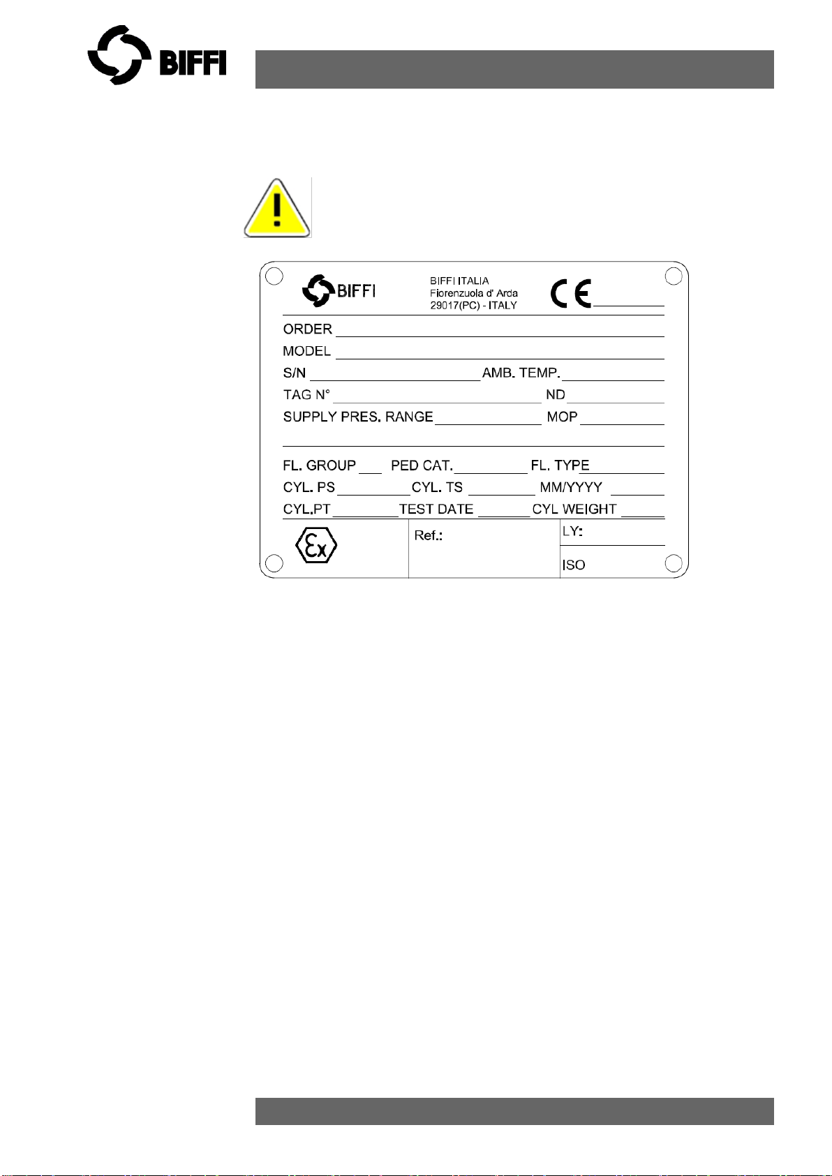
3) Check that the model, the serial number of the actuator and the
performance data written on the data-plate are in accordance with
those described on the order acknowledgement, test certificate
and delivery note.
4) Check that the fitted accessories comply with those listed in the
order acknowledgement and the delivery note.
2.2 Storage
The actuators leave the factory in excellent working conditions and
with an excellent finish (these conditions are guaranteed by an
individual inspection certificate); in order to maintain these
characteristics until the actuator is installed on the plant, it is
necessary to observe a few rules and take appropriate measures
during the storage period.
1) Make sure that plugs are fitted in the air connections and in the
cable entries. The plastic plugs, which close the inlets, do not have
a weatherproof function, but are only a means of protection
against the entry of foreign matter during transport. If long-term
storage is necessary and especially if the storage is outdoors,
metal plugs must replace the plastic protection plugs, which
guarantee a complete weatherproof protection.
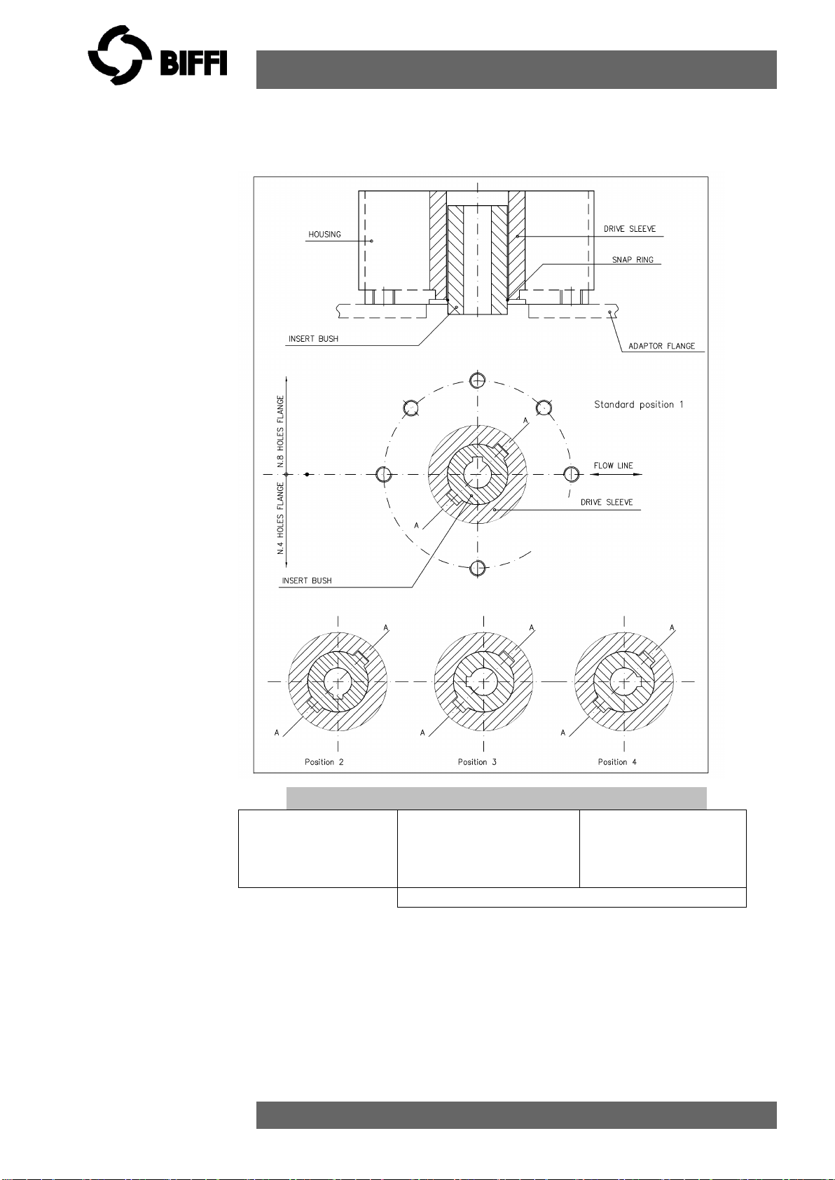
2) If the actuators are supplied separately from the valves, they must
be placed onto a wooden pallet so as not to damage the coupling
flange to the valve. In case of long-term storage, the coupling
parts (flange, drive sleeve, insert bush) must be coated with
protective oil or grease. If possible, blank off the flange by a
protection disk.
3) In case of long-term storage, it is advisable to keep the actuators
in a dry place or to provide at least some means of weather
protection. If possible, it is also advisable, to periodically operate
the actuator with filtered, dehydrated and lubricated air; after such

“ALGAS-MHP"
Use and maintenance manual
© Copyright by BIFFI Italia. All right reserved. page 8
Contents may change without notice
operations all the threaded connections of the actuator and the
valves of the control panel (if existing) should be carefully plugged.
2.3 Assembling the actuator onto the valve
2.3.1 Types of assembly
For coupling to the valve, the housing is provided with a flange with
threaded holes according to Biffi standard tables (SCN6200;
SCN6200-1; SCN6201; SCN6201-1). The number, dimensions and
diameter of the holes are made in accordance with ISO 5211, but for
actuator models 0.3 to 6 the holes are drilled on the centreline in
order to allow an easier assembly of an intermediate flange, when
required. This intermediate flange ( or spool-piece ) can be supplied
when the valve flange cannot directly match the actuator flange in its
“standard” configuration. For the biggest actuator models, the
actuator flange can be machined in accordance with the valve flange
dimensions.
The yoke has bored with keyways for coupling to the valve stem, the
dimensions of which are according to Biffi standard tables SCN6200*
and SCN6201*.

“ALGAS-MHP"
Use and maintenance manual
© Copyright by BIFFI Italia. All right reserved. page 9
Contents may change without notice

“ALGAS-MHP"
Use and maintenance manual
© Copyright by BIFFI Italia. All right reserved. page 10
Contents may change without notice

“ALGAS-MHP"
Use and maintenance manual
© Copyright by BIFFI Italia. All right reserved. page 11
Contents may change without notice
If required, for the standard models size 0.3 to 6, Biffi can supply an
insert bush with un-machined bore in accordance with Biffi standard
table SCN6202. On request the insert bush bore can be machined by
Biffi to couple the valve stem, provided its dimensions match the
maximum stem acceptance of the bush according to Biffi table
TN1005, enclosed. The particular execution of the flange and

“ALGAS-MHP"
Use and maintenance manual
© Copyright by BIFFI Italia. All right reserved. page 12
Contents may change without notice
bushing allow the actuator to be rotated by 90° in 4 different positions
according to the following figure:
Position 2 Position 3 Position 4
Rotate insert-bush
180° around
vertical-standard
position (1)
Rotate insert-bush
180° around axis A-A,
from position 2
Rotate insert-bush
180° around axis A-
A from position 1
Insert bush turned upside down
Picture 4 –Insert bush + intermediate coupling flange
The Biffi insert bush with 2 external keys at 45° allows to position the
keyway for the valve every 90°. Consequently actuator can be
mounted in 4 positions at 90° on top of the valve. For biggest
actuator models, the bore of the yoke can be machined according to
the dimensions of valve stem.

“ALGAS-MHP"
Use and maintenance manual
© Copyright by BIFFI Italia. All right reserved. page 13
Contents may change without notice
2.3.2 Valve stem with vertical axis :
The lifting and handling of the actuator must be done by
qualified personnel and in accordance with the laws and
regulations in force. Avoid the lifted actuator to be hung
above the personnel.
The actuator must be lifted by means of a suitable lifting
apparatus. The weight of the actuators is indicated in
the technical documentation attached to the equipment
itself.
For lifting and moving the actuator, use only hooks
fitted with safety latch, like the one, for example, shown
in follow figure 2.1
Figure 2.1 Example of hook with safety latch
Figure 2.2 –Lifting points: 1-2 (obligatory) 3 (balancing)

“ALGAS-MHP"
Use and maintenance manual
© Copyright by BIFFI Italia. All right reserved. page 14
Contents may change without notice
Lift ALGAS MHP actuators (pneumatic spring return) by means of the proper
lifting points represented and indicated on actuator by sticking labels. Also refer
to figures 2.2 for lifting points positions.
•For lifting unbalanced loads, use ropes of different lengths or
chains with adjustable length.
•Check each time the conditions of all lifting equipment used
and discard it if not in perfect working order.
•Do not knot or twist the ropes so as not to reduce the lifting
capacity or produce torsional effects on the load being lifted.
•Use the utmost caution and remain at a safe distance from
lifted actuator unless absolutely necessary; do not stand or
pass under suspended loads.
•Pay attention in putting under tension the ropes to prevent the
load shifting sideways in an uncontrolled manner.
•Use slings of such length that the angles of the leg from
vertical are as narrow as possible (MAX < 20°).
•During handling, do not transport the suspended actuator
above staff members in charge of the operation.
DO NOT USE the lifting eyelets on actuator to lift valve +
actuator assembly
Figure 2.3

“ALGAS-MHP"
Use and maintenance manual
© Copyright by BIFFI Italia. All right reserved. page 15
Contents may change without notice
Any lifting method different from what described above is
strictly forbidden.
BIFFI reject any responsibility for damages to goods or
injuries to persons coming from wrong lifting operations.
The actuator can be assembled onto the valve flange either by using
the actuator-housing flange with threaded holes, or by the
interposition of an adaptor flange or a spool piece.
The actuator drive sleeve is generally connected to the valve stem by
an insert bush or a stem extension.
The assembly position of the actuator, with reference to the valve,
must comply with the plant requirements (cylinder axis parallel or
perpendicular to the pipeline axis).
To assemble the actuator onto the valve proceed as follows:
1) Check that the coupling dimensions of the valve flange and stem,
or of the relevant extension, meet the actuator coupling
dimensions.
2) Bring the valve to the position related to the actuator spring
operation.
3) Lubricate the valve stem with oil or grease in order to make the
assembly easier. Be careful not to pour any of it onto the flange.
Figure 2.4

“ALGAS-MHP"
Use and maintenance manual
© Copyright by BIFFI Italia. All right reserved. page 16
Contents may change without notice
4) Clean the valve flange and remove anything that might prevent a
perfect adherence to the actuator flange and especially all traces
of grease, since the torque is transmitted by friction.
5) If an insert bush or stem extension for the connection to the valve
is supplied separately, assemble it onto the valve stem and fasten
it by tightening the proper stop dowels.
6) Bring the actuator to the position caused by the spring operation.
7) Connect a sling to the support points of the actuator and lift it:
make sure the sling is suitable for the actuator weight. When
possible, it is easier to assemble the actuator to the valve if the
valve stem is in the vertical position. In this case the actuator must
be lifted while keeping the flange in the horizontal position.
8) Clean the actuator flange and remove anything that might prevent
a perfect adherence to the valve flange and especially all traces of
grease.
9) Lower the actuator onto the valve in such a way that the insert
bush, assembled on the valve stem, enters the actuator drive
sleeve. This coupling must take place without forcing and only with
the weight of the actuator. When the insert bush has entered the
actuator drive sleeve, check the holes of the valve flange. If they
do not meet with the holes of the actuator flange or the stud bolts
screwed into them, the actuator drive sleeve must be rotated; feed
the actuator cylinder with air at proper pressure, indicated on data-
sheet for actuator.
10)Tighten the nuts of the connecting stud bolts evenly with the
torque prescribed in the table. The stud bolts must be made of
ASTM A320 L7 steel; the nuts must be made of ASTM A194 grade
2 steel.

“ALGAS-MHP"
Use and maintenance manual
© Copyright by BIFFI Italia. All right reserved. page 17
Contents may change without notice
THREAD SIZE
RECOMMENDED TIGHTENING
TORQUE (Nm)
M8
20
M10
40
M12
70
M14
110
M16
160
M20
320
M22
420
M24
550
M27
800
M30
1100
M33
1400
M36
1700
11)If possible, operate the actuator to check that it moves the
valve smoothly.
2.3.3 Valve stem with horizontal axis :
The actuator can also be lifted to assemble directly onto the valve
with stem with horizontal axis. To make a correct lifting procedure
proceed as follow:
1) Connect properly the actuator lifting points 1 with chains, and
connect by suitable slings the support brackets 2 and 3

“ALGAS-MHP"
Use and maintenance manual
© Copyright by BIFFI Italia. All right reserved. page 18
Contents may change without notice
2) Balance the weight and lift the actuator until to make possible the
rotation of actuator in its final mounting position, with cylinder on
top, or spring container placed on top, as showed in the following
images:

“ALGAS-MHP"
Use and maintenance manual
© Copyright by BIFFI Italia. All right reserved. page 19
Contents may change without notice
3) Clean the actuator flange and remove anything that might
prevent a perfect adherence to the valve flange and especially all
traces of grease.
4) Lift the actuator near to the valve in such a way that the insert
bush, assembled on the valve stem, enters the actuator drive
sleeve without forcing the coupling . When the insert bush has
entered the actuator drive sleeve, check the holes of the valve
flange. If they do not meet with the holes of the actuator flange or
the stud bolts screwed into them, the actuator drive sleeve must
be rotated; feed the actuator cylinder with air at proper pressure,
indicated on data-sheet for actuator.
5) Tighten the nuts of the connecting stud bolts evenly with the
torque prescribed in the table. The stud bolts must be made of
ASTM A320 L7 steel; the nuts must be made of ASTM A194
grade 2 steel.
6) If possible, operate the actuator to check that it moves the valve
smoothly.

“ALGAS-MHP"
Use and maintenance manual
© Copyright by BIFFI Italia. All right reserved. page 20
Contents may change without notice
3 Operation and Use
3.1 Setting of the angular stroke
It is important that the mechanical stops of the actuator (and not
those of the valve) stop the angular stroke at both extreme valve
position (fully open and fully closed), except when this is required by
the valve operation (e.g. metal seated butterfly valves).
The travel stop screws are screwed into the end flange of the
hydraulic cylinder for MHP, depending on actuator different
configuration (i.e. spring to open or spring to close), and spring
cartridge.
The setting of the open valve position is performed by adjusting the
travel stop screw on the left side of the actuator.
The setting of the closed valve position is performed by adjusting the
travel stop screw on the right side of the actuator.
3.1.1 Travel stop screw screwed on the end flange of
hydraulic cylinder
For the adjustment of the travel stop screws proceed as follows :
1) Remove the protection plug (t) with proper wrench c1.
2) Loosen the stopper-protection with a proper wrench c3.
3) If the actuator angular stroke is stopped before reaching the end
position (fully open or closed), unscrew the stop screw (g) by turning
it anticlockwise with a proper wrench (c2) , until the valve reaches the
right position. When unscrewing the stop screw, keep attention that
the protection still with a wrench so that the sealing washer doesn’t
withdraw together with the screw.
4) If the actuator angular stroke is stopped beyond the end position
(fully open or closed valve), screw the stop screw by turning it
clockwise until the valve reaches the right position.
5) Tighten the protection for stopper and the plug (t)
Other manuals for ALGAS-MHP
1
Table of contents
Other BIFFI Industrial Equipment manuals