BIFFI ICON3000 Series User manual
Installation, Operation and Maintenance Manual
DTDE 536 Rev. 1
March 2021
Bif ICON3000
Partial Stroke Test
Copyright © Bif. The information in this document is subject to change without notice. Updated data sheets can be obtained from our website www.bif.it or from your nearest Bif Center:
Bif Italia s.r.l. - Strada Bif 165, 29017 Fiorenzuola d'Arda (PC) – Italy PH: +39 0523 944 411 – bif_italia@bif.it

Installation, Operation and Maintenance Manual
DTDE 536 Rev. 1
Revision Details
March 2021
Revision Details
Rev Date Prepared Approved Notes
1 March 2021 Migration to new template
0January 2019 L. Piacenti A. Battaglia Issue
Revision Details

i
Installation, Operation and Maintenance Manual
DTDE 536 Rev. 1
Table of Contents
March 2021
Table of Contents
Table of Contents
Section 1: Partial Stroke Test (PST)
Partial Stroke Test (PST) .......................................................................................... 1
Section 2: Parameters of Partial Stroke Test
Parameters of Partial Stroke Test............................................................................. 3
Section 3: Command to Initiate the PST Cycle
Command to initiate the PST Cycle.......................................................................... 4
Section 4: Reset of PST Cycle
Reset of PST Cycle ................................................................................................... 5
Section 5: PST Curves and PST Baseline
PST Curves and PST Baseline ................................................................................... 6
Section 6: PST Report and Warning
PST Report and Warning ......................................................................................... 7
Section 7: Remote Signalling
Remote Signalling................................................................................................... 8
Section 8: Local Operator Interface
8.1 Procedure to Initiate PST by Local Command................................................. 9
8.2 Procedure to Select the BASELINE ................................................................. 9
8.3 Procedure to Set PST Parameters ................................................................ 10

Installation, Operation and Maintenance Manual
DTDE 536 Rev. 1
Notes
March 2021
This page intentionally left blank

Installation, Operation and Maintenance Manual
DTDE 536 Rev. 1 March 2021
Partial Stroke Test (PST) 1
Section 1: Partial Stroke Test (PST)
NOTICE
This Manual gives instruction regarding only the Partial Stroke Test function of ICON3000; detailed
and complete information for setting and control of the Electric Actuator ICON3000 are in the
ICON3000 Installation, Operation and Maintenance Manual, VCIOM-14012-EN which is part of the
mandatory instructions documentation.
! WARNING
It is assumed that installation, setting, commissioning, maintenance and repair works on ICON3000
are carried out by qualied personnel and checked by responsible specialists.
Section 1: Partial Stroke Test (PST)
The function Partial Stroke Test (PST) of ICON3000 is used to check the actuator and valve
functionality while they are in service in the pipeline. The test is performed only if the actuator
is fully open or closed.
PST function is available only if the setting of parameter “Restricted, Interlock mode” of ICON3000
is “Advanced.” In the above condition the hardwired inputs B4 and B5 of ICON3000 terminal board
work as input commands to initiate the PST cycle. Firmware version of ICON3000 base card should
be > = 9.00.
The following table shows the operation of the above inputs in function of parameter
“Interlock mode,” in the “VIEW and SETUP menu, Restricted,” (see Installation, Operation and
Maintenance Manual of ICON3000, VCIOM-14012-EN).
Table 1.
The PST cycle (Partial Stroke Test) consists in the following steps:
• To drive the electrical motor to move the valve to the congured position (PST travel)
• To measure the time to reach the congured position (T-PST)
• To stop the motor when congured position is reached and measure the over-travel
% (OV-TR)
• To stay in position for a congured time
• To drive of the motor to move the valve in opposite direction to the initial position
• To measure the time to return to the initial position (T-RET)
ICON3000 Parameter
“Restricted, Interlock mode”
Terminal B4 of ICON3000
terminal board
Terminal B5 of ICON3000
terminal board
advanced PST in Open direction PST in Close direction
standard Interlock in Open direction Interlock in Close direction
0
March 2021
Installation, Operation and Maintenance Manual
DTDE 536 Rev. 1
Partial Stroke Test (PST)2
Section 1: Partial Stroke Test (PST)
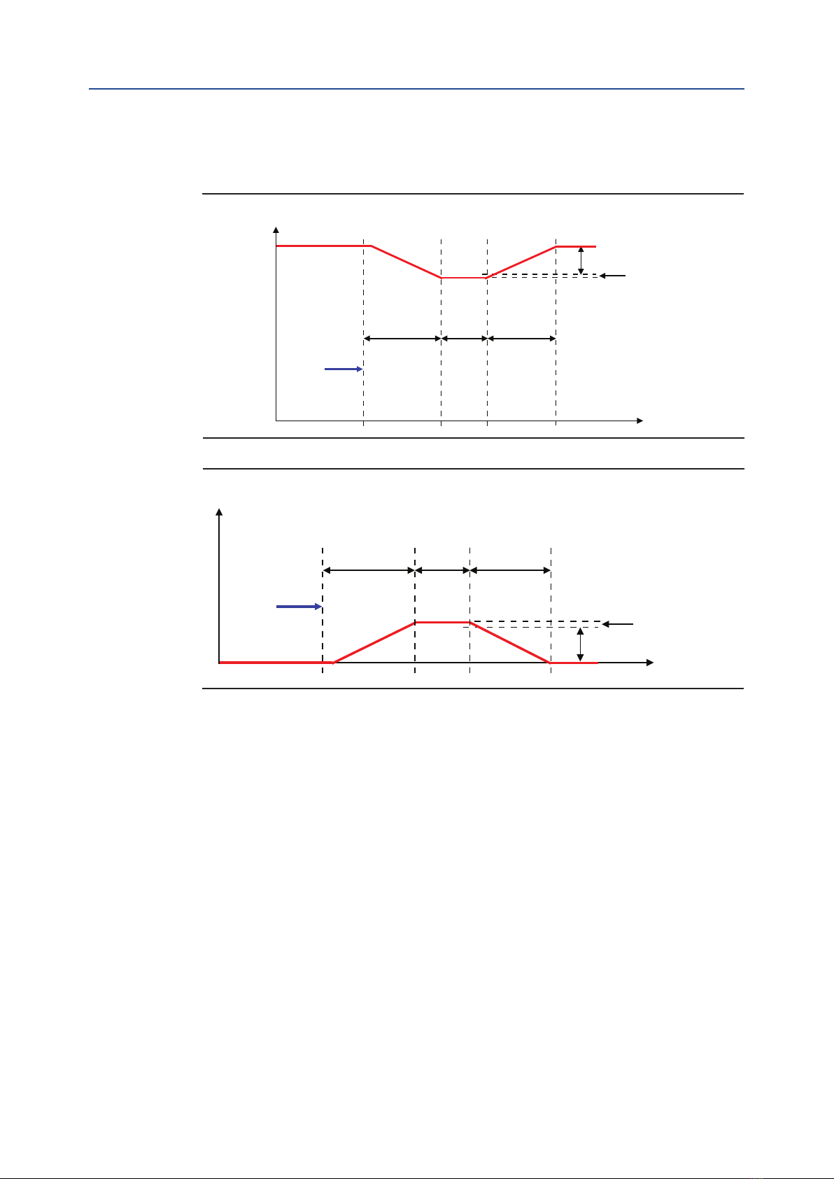
The following gures show the actuator position % versus time in case of PST in closing and
opening direction.
Figure 1
100 100
PST travel %
Over-travel % (OV-TR)
T-RET
T-PST Stay in
position
Time seconds
Position %
Cmd to
initiate
PST
PST in closing
direction
Position %
0
PST travel %
Time seconds
Cmd to
initiate
PST
PST in closing
direction
Over-travel % (OV-TR)
T-RET
T-PST Stay in
position
Figure 2

Installation, Operation and Maintenance Manual
DTDE 536 Rev. 1 March 2021
Parameters of PST 3
Section 2: Parameters of PST
Section 2: Parameters of Partial Stroke Test
The following parameters are available in the local operator interface of ICON3000, VIEW and SETUP
menu, ACTUATOR SETUP, PST SETUP routine, to set PST function behavior:
1. PST mode: OFF, AUTO, MANUAL
— OFF: PST function disabled
— AUTO: PST cycle carried out automatically and cyclically with time interval set by
the parameter PERIOD and at time set by the parameter HOUR of DAY
— MANUAL: PST cycle carried out on receiving of a remote hardwired PST signal
or by local command available in the “VIEW and SETUP menu, Maintenance
functions” of ICON3000
— MAN-AUTO: both automatic and manual mode initiate the PST function
2. PERIOD: time interval between PST’s in days, congurable from 1 to 1000, in PST mode “AUTO”
3. HOUR of DAY: hour of PST, in hour, congurable from 0 - 23, in PST mode “AUTO”
4. PST TRAVEL: position travel during PST cycle, in % of position, congurable from 5 - 40.
If actuator is fully open it moves from 100% to “100-PST TRAVEL %”, if actuator is fully
closed it moves from 0% to “PST TRAVEL %”
5. MAX T-PST: max time allowed carrying out the PST TRAVEL, measured in % of relevant
BASELINE time, congurable from 1 - 1000%
6. MAX PST T-RET: max time allowed to return to initial position, measured in % of relevant
BASELINE time, congurable from 1 - 1000%
7. PAUSE: time of stay in position of actuator, in seconds, congurable from 2 - 255 seconds
8. MAX PST OV-TR: max position over-travel allowed to actuator during PST cycle, in
percentage of position , congurable from 1 - 100

March 2021
Installation, Operation and Maintenance Manual
DTDE 536 Rev. 1
Command to PST Cycle4
Section 3: Command to PST Cycle
Section 3: Command to Initiate the PST Cycle
PST cycle initiates only if:
• actuator is fully open or closed
• local selector of actuator is in REMOTE or LOCAL
• local STOP, remote STOP (only in the option 4 wires mode) and ESD are not active
The parameter “PST mode” sets the following modes to initiate PST cycle:
• “AUTO”: the PST cycle initiates at the hour set by the parameter HOUR of DAY and when
the time past from the last PST is equal to parameter PERIOD. The test is performed if the
actuator local selector is in LOCAL or REMOTE.
• “MANUAL”: if the ICON3000 local selector is in REMOTE, the PST is performed on receiving
of the hardwired command on the ICON3000 terminal board. Terminal B4 is the input to
perform PST in open direction and terminal B5 is the input to perform PST in close direction.
Refer to relevant electrical diagram for wiring details. If the ICON3000 local selector is in
LOCAL, the PST can be initiated by the command available in the menu “VIEW and SETUP
menu, SETUP, MAINTENANCE routines, PST cmd”.
• “MAN-AUTO”: both conditions described in “AUTO” and “MANUAL” initiate PST action.

Installation, Operation and Maintenance Manual
DTDE 536 Rev. 1 March 2021
Reset of PST Cycle 5
Section 4: Reset of PST Cycle
Section 4: Reset of PST Cycle
PST cycle aborts in the following conditions:
• To move the ICON3000 Local selector to OFF, LOCAL or REMOTE while PST cycle
is in progress
• Alarm of electrical actuator ICON3000
• To press the Local STOP pushbutton
• To press the remote STOP command (only if option “4-wires” is used, see Installation,
Operation and Maintenance Manual of ICON3000, VCIOM-14012-EN, Remote Control)
• ESD command

March 2021
Installation, Operation and Maintenance Manual
DTDE 536 Rev. 1
PST Curves and Baseline6
Section 5: PST Curves and Baseline
Section 5: PST Curves and PST Baseline
During PST cycle the actuator position % and the relevant time are collected in the RAM memory
of ICON3000. At the end of PST cycle the PST prole (position versus time) is memorized in the
permanent memory. The memory contains up to 16 PST proles. When a new set of data is available
the oldest prole is deleted and the new one is stored.
By the command “SET PST REFERENCE”, available in the local operator interface, option “VIEW and
SETUP menu, SETUP, MAINTENANCE” routines, 1 out off 16 “PST curves” can be copied and frozen in
the “PST BASELINE” memory.
The BASELINE curve can also be done by the PST command, available in the “VIEW and SETUP menu,
SETUP, MAINTENANCE, PST cmd” routines. By selecting the option “BASELINE” the PST command
causes the PST cycle execution and the collected data are saved in the PST BASELINE memory.
The “PST BASELINE” can be updated only by a new “SET PST BASELINE” command.By the comparison
between PST BASELINE and PST curves, the ICON3000 can produce status and warning useful in
maintenance operation.
By PC or PDA and A-Manager software tool, the curves can be read from ICON3000 and then
visualized and compared in a graph.
Figure 3 Example of PST in opening
PST curve in opening: gray line
BASELINE curve: black line
Figure 4 PST curve details
PST curve details

Installation, Operation and Maintenance Manual
DTDE 536 Rev. 1 March 2021
PST Report and Warning 7
Section 6: PST Report and Warning
Section 6: PST Report and Warning
At the end of PST cycle the new data collected are compared with the BASELINE and the setpoints
“MAX T-PST, MAX PST T-RET, MAX PST OV-TR to produce the following status and warnings:
Table 2.
Warning can be viewed by the local operator interface of ICON3000 or by a PC/PDA connected
via Bluetooth interface. Warnings are also recorded in the warning log registers (see Installation,
Operation and Maintenance Manual of ICON3000, VCIOM-14012-EN, VIEW and SETUP menu,
maintenance routines).
Status Description Warning Note
Passed Test OK No message on the
ICON3000 display
Reset test aborted PST See reset conditions
T-PST failed time T-PST T-PST See parameter MAX
T-PST
T-RET failed time T-RET T-RET See parameter MAX
PST T-RET
OV-TR PST over-travel OV-TR See parameter MAX
PST OV-TR
Failed at least two of T-PST,
T-RET, OV-TR, reset Failed

March 2021
Installation, Operation and Maintenance Manual
DTDE 536 Rev. 1
Remote Signalling8
Section 7: Remote Signalling
Section 7: Remote Signalling
The following conditions can be individually congured to switch the auxiliary relays As1 - As8.
• PST active: PST cycle in progress.
• PST failed: it summarizes T-PST, T-RET, OV-TR and reset. The status of relay “PST failed”
can be reset by a manual reset of warning via actuator local operator interface or
alternatively by a new PST command.

Installation, Operation and Maintenance Manual
DTDE 536 Rev. 1 March 2021
Local Operator Interface 9
Section 8: Local Operator Interface
Section 8: Local Operator Interface
When PST cycle is in progress the display of ICON3000 shows the message “PST ON”.
The following paragraphs report the instructions to operate with PST function by the Local
Operator Interface of ICON3000 (refer to Installation, Operation and Maintenance Manual of
ICON3000, VCIOM-14012-EN for detailed instruction relevant to conguration options via ICON3000
Local Operator Interface).
8.1 Procedure to Initiate PST by Local Command
1. Move the local selector in OFF and then simultaneously press OPEN and STOP. Select
the language, enter the password and press YES to select SETUP MODE (see Installation,
Operation and Maintenance Manual of ICON3000, VCIOM-14012-EN, Local Controls).
2. Press NO and again NO until the display shows MAINTENANCE. Press YES.
3. Press NO to scroll the list of options and press YES when the display shows “PST cmd”.
4. Press YES to conrm “NEW BASELINE disabled”, press YES to execute a normal PST cycle,
press NO and then YES to execute a “NEW BASELINE”.
5. Press YES to conrm and then move the local selector in LOCAL.
6. PST cycle starts, the ICON display shows the message “PST ON”.
7. At the end of PST cycle the message “PST ON” disappears and actuator is available to
normal operations.
8.2 Procedure to Select the BASELINE
1. Move the local selector in OFF and then s and then simultaneously press OPEN and
STOP. Select the language, enter the password and press YES to select SETUP MODE
(see Installation, Operation and Maintenance Manual of ICON3000, VCIOM-14012-EN,
Local Controls).
2. Press NO and again NO until the display shows MAINTENANCE. Press YES.
3. Press NO to scroll the list of options and press YES when the display shows “PST REFERENCE”.
4. In the menu SEL. CURVE select the curve number. Press NO to change, press YES to conrm.
The most recent curve is the n° 16 is and the oldest one is the n°1.
5. Press YES to conrm. The display shows the message REFERENCE OK. Now the new
BASELINE is the curve selected at the previous step.
6. The display returns to “SET PST REFERENCE”. Press simultaneously YES and NO to exit
from menu.
-------------
LOCAL
PST ON
------------- next
REMOTE
PST ON

March 2021
Installation, Operation and Maintenance Manual
DTDE 536 Rev. 1
Local Operator Interface10
Section 8: Local Operator Interface
8.3 Procedure to Set PST Parameters
Detailed instructions of ICON3000 menu are in the Installation, Operation and Maintenance Manual
of ICON3000, VCIOM-14012-EN, Local Controls.
Move the local
selector in OFF
and then press
simultaneously
OPEN and
STOP
Press NO
to select
SETUP MODE
Press YES to
select SETUP
MODE
Press YES
to select
ACTUATOR
SETUP and
switch to
next step
Enter
password
Press NO to scroll
the list of languages
and press YES when
the display shows
the desired language
and to switch to
next step

Installation, Operation and Maintenance Manual
DTDE 536 Rev. 1 March 2021
Local Operator Interface 11
Section 8: Local Operator Interface
Press NO to scroll
the list of options
and press YES when
the display shows
“PST SETUP”
Press YES if desired
option is MANUAL
and switch to next
parameter PERIOD
Press NO to change
PERIOD. Press YES
to set the PERIOD
and switch to next
parameter
HOUR of DAY
Press NO to
change PST
TRAVEL. Press
YES to set the PST
TRAVEL and switch
to next parameter
MAX T-PST
Press NO to select
PST MODE.
Options available
are OFF, MANUAL,
MAN-AUTO
Press YES if
desired option
is MAN-AUTO
and switch to
next parameter
PERIOD
Press NO to
change HOUR
of DAY. Press
YES to set the
HOUR of DAY
and switch to
next parameter
PST TRAVEL
Press NO to
change MAX
T-PST. Press
YES to set the
MAX T-PST and
switch to next
parameter MAX
PST T-RET
Press NO to
change MAX PST
T-RET. Press YES
to set the MAX
PST T-RET and
switch to next
parameter PAUSE
Press NO to
change MAX
PST OV-TR.
Press YES to
set the MAX
PST OV-TR. and
switch to
PST SETUP
Press NO to
change PAUSE.
Press YES to set
the PAUSE and
switch to next
parameter MAX
PST OV-TR
Press
simultaneously
YES and NO to
exit from PST
SETUP menu

VCIOM-16358-EN ©2020 Biffi. All rights reserved.
The contents of this publication are presented for information purposes only,
and while every effort has been made to ensure their accuracy, they are not
to be construed as warranties or guarantees, express or implied, regarding
the products or services described herein or their use or applicability. All sales
are governed by our terms and conditions, which are available on request.
We reserve the right to modify or improve the designs or specifications of our
products at any time without notice.
Biffi Italia s.r.l.
Strada Biffi 165
29017 Fiorenzuola d’Arda (PC)
Italy
T +39 0523 944 411
For complete list of sales and manufacturing sites, please visit
Other manuals for ICON3000 Series
10
Table of contents
Other BIFFI Industrial Equipment manuals


Popular Industrial Equipment manuals by other brands


TTM
TTM MAG 250 Installation, Operating and Maintenance Instruction

Gamry Instruments
Gamry Instruments Faraday Shield Operator's manual

GSSI
GSSI UtilityScan 350HS quick start guide

REGULA
REGULA 7708 operating manual

Dixon
Dixon 200-PV-9 Maintenance & Operating Intructions

cytiva
cytiva Whatman operating instructions