BIFFI HLDA User manual

HLDA –Double acting - Doubled thrust hydraulic linear actuator
Use and maintenance manual
© Copyright by BIFFI Italia. All right reserved. Pag. 1
Contents may change without notice
MAN 668
Use and maintenance manual
HLDA
DOUBLED-THRUST DOUBLE
ACTING HYDRAULIC
LINEAR ACTUATOR
2
23/05/18
Updated data-plate
Ermanni
Orefici
Vigliano
1
30/03/17
Updated document
Ermanni
Orefici
Vigliano
0
05/05/99
Document release
Lazzarini
Aliani
Ziveri
Rev.
Date
Description
Prepared
Checked
Approved

HLDA –Double acting - Doubled thrust hydraulic linear actuator
Use and maintenance manual
© Copyright by BIFFI Italia. All right reserved. Pag. 2
Contents may change without notice
TABLE OF CONTENTS
1General warnings ................................................................ 4
1.1 GENERALITIES..........................................................................4
1.1.1Applicable regulation...............................................................4
1.1.2Terms and conditions..............................................................4
1.2 Identification plate .......................................................................5
1.3 INTRODUCING THE ACTUATOR..............................................5
1.4 DATA SHEET..............................................................................8
2Installation........................................................................... 8
2.1 CHECKS UPON ACTUATOR RECEIPT.....................................8
2.2 ACTUATOR HANDLING.............................................................9
2.3 STORAGE.................................................................................10
2.4 ACTUATOR ASSEMBLY ON THE VALVE ...............................11
2.4.1Types of assembly ................................................................11
2.4.2Assembly procedure..............................................................11
2.5 HYDRAULIC CONNECTIONS..................................................14
2.6 ELECTRICAL CONNECTIONS (IF ANY)..................................15
2.7 COMMISSIONING ....................................................................15
3Operation and use ............................................................. 17
3.1 OPERATION DESCRIPTION....................................................17
3.2 RESIDUAL RISKS.....................................................................18
3.3 OPERATIONS...........................................................................18
( refer to specific document: BIFFI operating diagram furnished )...18
3.3.1Emergency manual operation (MHP)....................................18
3.3.2Remote control operations :..................................................18
3.4 CALIBRATION OF THE ANGULAR STROKE ..........................21
3.5 CALIBRATION OF MICROSWITCHES (biffi limit switch box only)
23
3.5 CALIBRATION OF THE OPERATION TIME.............................25
4Operational tests and inspections...................................... 26
5Maintenance ...................................................................... 27
5.1 PERIODIC MAINTENANCE......................................................27
5.1.1Check and restore oil level in the hydraulic manual handpump
( refer to chapt. 7.2 table 3 )..................................................28
5.2 EXTRAORDINARY MAINTENANCE ........................................30
5.2.1Lubrication of mechanism .....................................................30
5.3 DISMANTLING AND DEMOLITION...........................................34
6Troubleshooting ................................................................ 36
6.1 FAILURE OR BREAKDOWN RESEARCH ...............................36
7Layouts.............................................................................. 37
7.1 Spare parts order ......................................................................37
7.2 parts-list for maintenance and replacing procedure...................38
8Date report for maintenance operations.................................. 44

HLDA –Double acting - Doubled thrust hydraulic linear actuator
Use and maintenance manual
© Copyright by BIFFI Italia. All right reserved. Pag. 3
Contents may change without notice
NOTE:
BIFFI Italia S.r.l pays the highest attention to collecting and verifying the
documentation contained in this user manual. However BIFFI Italia S.r.l. is not
liable for any mistakes contained in this manual, for damage or accidents due to
the use of the latter. The information contained is of exclusive reserved ownership
of BIFFI Italia S.r.l and may be modified without prior notice. All rights reserved.

HLDA –Double acting - Doubled thrust hydraulic linear actuator
Use and maintenance manual
© Copyright by BIFFI Italia. All right reserved. Pag. 4
Contents may change without notice
1General warnings
The manual is an integral part of the machine, it should
be carefully read before carrying out any operation and
it should be kept for future references.
1.1 GENERALITIES
BIFFI Italia S.r.l actuators are conceived, manufactured and
controlled according to the Quality Control System in compliance with
EN-ISO 9001 international regulation.
1.1.1 Applicable regulation
EN ISO 12100:2010: Safety of machinery –General principles for
design –Risk assessment and risk reduction
2006/42/EC: Machine directive.
2014/68/EU: Directive for pressure PED equipment
2014/35/EU: Directive for low voltage equipment
2014/30/EU: Directive for the electromagnetic compatibility
2014/34/EU: Directive and safety instructions for use in
hazardous area
1.1.2 Terms and conditions
Biffi Italia srl guarantees that all the items produced are free of
defects in workmanship and manufacturing materials and meet
relevant current specifications, provided they are installed, used and
serviced according to the instructions contained in the present
manual. The warranty can last either one year from the date of
installation by the initial user of the product, or eighteen months from
the date of shipment to the initial user, depending on which event
occurs first. All detailed warranty conditions are specified in the
documentation forwarded together with the product. This warranty
does not cover special products or components not warranted by
subcontractors, or materials that were used or installed improperly or
were modified or repaired by unauthorized staff. In the event that a
fault condition be caused by improper installation, maintenance or
use, or by irregular working conditions, the repairs will be charged
according to applicable fees. The warranty and Biffi Italia srl

HLDA –Double acting - Doubled thrust hydraulic linear actuator
Use and maintenance manual
© Copyright by BIFFI Italia. All right reserved. Pag. 5
Contents may change without notice
liability shall lapse in the event that any modification or
tampering whatsoever be performed on the actuator.
1.2 IDENTIFICATION PLATE
It is forbidden to modify the information and the marks without
previous written authorization by BIFFI Italia S.r.l.
The plate fastened on the actuator contains the following information
(Figure1).
Figure 1 –Data plate
1.3 INTRODUCING THE ACTUATOR
HLDA double acting & doubled thrust hydraulic linear actuators, are
suitable to operate the kind of linear valves with rising-stem or
requiring a high thrust value in the first phase of valve opening and
with lower values during the complete stroke ( wedge gate valves,
through conduit gate valves) for ON-OFF and modulating heavy-duty
service. The actuator is made up of an hydraulic cylinder and a
mounting pedestal complete with a joint for the coupling to the valve
stem of actuator output stem. The valve is actuated in opening and in
closing position by the actuator hydraulic cylinder that is pressurized
in one or in the other direction.
In the first part of the stroke, the total thrust section is obtained by the
double-piston

HLDA –Double acting - Doubled thrust hydraulic linear actuator
Use and maintenance manual
© Copyright by BIFFI Italia. All right reserved. Pag. 6
Contents may change without notice
When the double piston has completed the stroke, the remaining
stroke is performed only by the piston

HLDA –Double acting - Doubled thrust hydraulic linear actuator
Use and maintenance manual
© Copyright by BIFFI Italia. All right reserved. Pag. 7
Contents may change without notice
The section ratio between the first part of the stroke and the
remaining stroke is about two areas.
This type of solution, reduce the oil displacement of the actuator,
allowing lower volume of the accumulators for the emergency
strokes.
The linear stroke of the valve is adjustable by means of the external
mechanical stop for upward position and by the adjustment of the
coupling of valve stem to actuator joint for the downward position.
The actuator pedestal has a flange with threaded holes to fix the
actuator to the valve.
BIFFI can supply different types of control system following
Customer’s requirements.
The expected lifetime of actuator is approximately 25 years .
Figure 2 –Identification of actuator parts
Hydraulic cylinder
Valve coupling
Emergency hydraulic
accumulators
Lifting eyelets

HLDA –Double acting - Doubled thrust hydraulic linear actuator
Use and maintenance manual
© Copyright by BIFFI Italia. All right reserved. Pag. 8
Contents may change without notice
1.4 DATA SHEET
2Installation
2.1 CHECKS UPON ACTUATOR RECEIPT
❑Check that the model, the serial number of the actuator and the
technical data reported on the identification plate correspond with
those of order confirmation (Sect. 1.2).
❑Check that the actuator is equipped with the fittings as provided for
by order confirmation.
❑Check that the actuator was not damaged during transportation: if
necessary renovate the painting according to the specification
reported on the order confirmation.
❑If the actuator is received already assembled with the valve, its
settings have already been made at the factory.
If the actuator is delivered separately from the valve, it is
necessary to check, and, if required, to adjust, the settings of the
mechanical stops (Sect. 3.4) and of micro-switches (if any) (Sect.
3.5).
Supply fluid
Mineral oil or synthetic fluids
Design pressure
Output thrust
350 bar g
Double acting thrust up to 8000000 N
Operating temperature
Standard: from –30°C to +100°C
Optional: from –60° to +140°C
Applications
Gate, Globe valves

HLDA –Double acting - Doubled thrust hydraulic linear actuator
Use and maintenance manual
© Copyright by BIFFI Italia. All right reserved. Pag. 9
Contents may change without notice
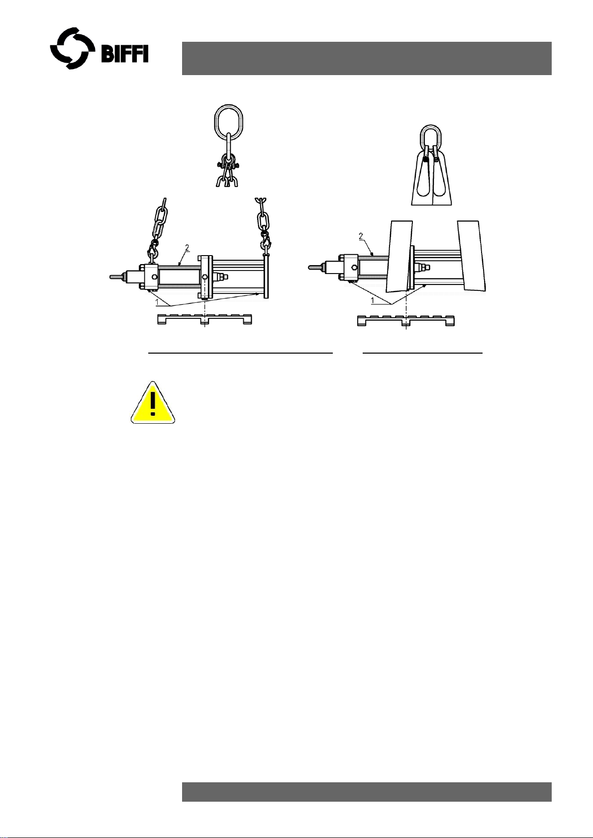
2.2 ACTUATOR HANDLING
The lifting and handling should be made by qualified staff
and in compliance with the laws and provisions in force.
The fastening points are appropriate for the lifting of the
actuator alone and not for the valve + actuator assembly.
Avoid that during the handling, the actuator passes above
the staff.
The actuator should be handled with appropriate lifting
means. The weight of the actuator is reported on the
delivery bill.
Picture 1 –Lifting points for HLDA actuators
1 = Lifting points ( obligatory )
HLDA –Double acting - Doubled thrust hydraulic linear actuator
Use and maintenance manual
© Copyright by BIFFI Italia. All right reserved. Pag. 10
Contents may change without notice
Picture 2 - Positioning by chains Positioning by slings
1 = point of support - 2 = don’t lay the actuator on tie-rods of
cylinder
3 = don’t lay the actuator on accessories ( manual hand-pump,
hydraulic control system etc. )
2.3 STORAGE
If the actuator needs storage, before installation follow these steps:
❑Place it on a wood surface in order not to deteriorate the area of
valve coupling.
❑Make sure that plastic plugs are present on the hydraulic and
electrical connections (if present).
❑Check that the cover of the control group and of the limit switch box
(if any) are properly closed.
If the storage is long-term or outdoor:
❑Keep the actuator protected from direct weather conditions.
❑Replace plastic plugs of hydraulic and electrical connections (if any)
with metal plugs that guarantee perfect tightness.
❑Coat with oil, grease or protection disc, the valve coupling area.
❑Periodically operate the actuator (Sect. 3.3).

HLDA –Double acting - Doubled thrust hydraulic linear actuator
Use and maintenance manual
© Copyright by BIFFI Italia. All right reserved. Pag. 11
Contents may change without notice
2.4 ACTUATOR ASSEMBLY ON THE VALVE
2.4.1 Types of assembly
The adapter pedestal in fabricated carbon steel is specifically
designed for adaptation to any type of valve with provision for local
indicator, limit switches and other accessories (on request).
Lift the actuator by safety-hook for chains using the lifting-points (see
sect. 2.2) on the top of actuator for handling, transporting and
assembling in vertical position (see picture 1). For handling,
transporting and assembling the actuator in horizontal position by
safety-hook for chains use the lifting-points on the top of cylinder
head-flange and on coupling flange (see picture 2).
2.4.2 Assembly procedure
Failure to comply with the following procedures may
impair product warranty. Installation, commissioning
and maintenance and repair works should be carried
out by qualified staff.
A non-conforming assembly could be the source of
serious accidents.
For actuator assembly on the valve:
Check that the assembly position, as shown on the
documentation, complies with system’s geometry.
Check the consistency of the parts of actuator-valve
coupling.
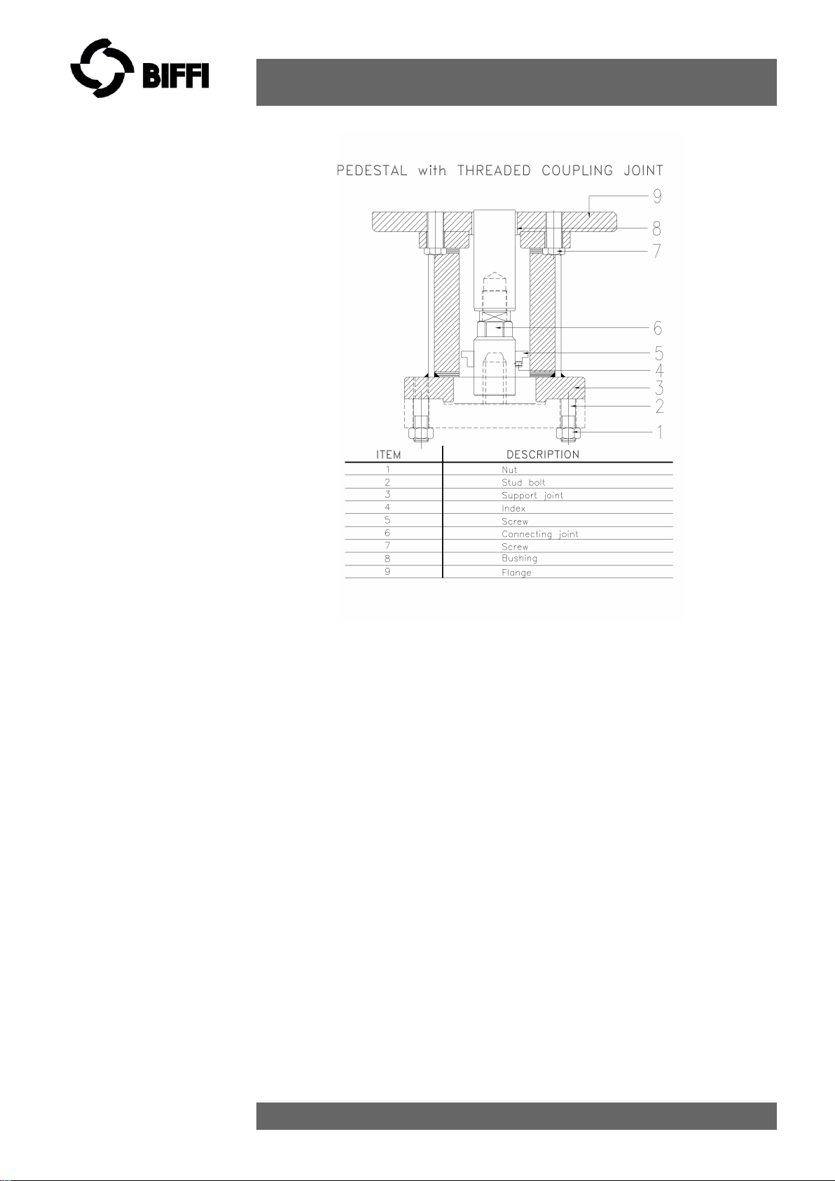
A) TO ASSEMBLE THE ACTUATOR ONTO THE VALVE BY BRACKET
WITH THREADED JOINT PROCEED AS FOLLOWS:
HLDA –Double acting - Doubled thrust hydraulic linear actuator
Use and maintenance manual
© Copyright by BIFFI Italia. All right reserved. Pag. 12
Contents may change without notice
1) Check that the coupling dimensions of the valve flange and stem,
or of the relevant extension, meet the actuator coupling
dimensions (valve stem and flange). Lubricate the valve stem with
grease in order to make the assembly easier.
2) Connect a sling to the support point of the actuator and lift it.
To make easier the assembly , the valve stem has to be in perfect
vertical position.
Note: the eyebolt is sized for the lifting of the only actuator (NOT
ACTUATOR+VALVE). Proper lifting points have to be foreseen for
the valve.
3) . Screw the actuator coupling joint onto the valve by rotating the
actuator, or screw down the valve stem stroke-ring with Red
Loctite 542 and fix the half-bearings. When the threaded holes of
the actuator flange are in correspondence with the holes on the
valve flange screw the proper stud bolts. Screw the nuts on the
stud bolts and tighten up the valve flange is in contact with the
actuator flange.
4) Tighten the nuts of the connecting stud bolts evenly with the
torque prescribed in the table. The stud bolts must be made of
ASTM A320 L7 steel, the nuts must be made of ASTM A194 grade
2 steel as minimum.
HLDA –Double acting - Doubled thrust hydraulic linear actuator
Use and maintenance manual
© Copyright by BIFFI Italia. All right reserved. Pag. 13
Contents may change without notice
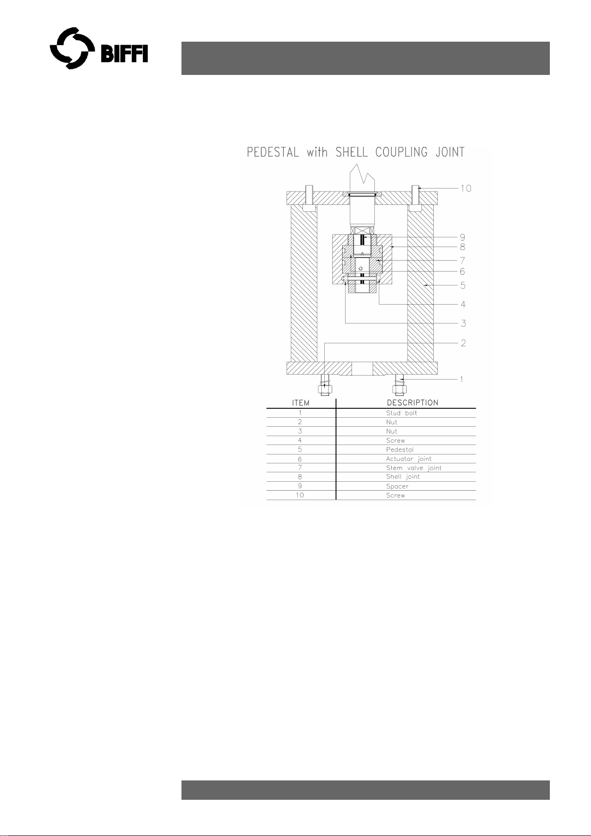
B) To assemble the actuator onto the valve by bracket with shell
joint, perform the following operations:
1) -Check that the coupling dimensions of the valve flange and stem, or of
the relevant extension, meet the actuator coupling dimensions (valve
stem and flange). Lubricate the valve stem with grease in order to make
the assembly easier
2) To make easier the assembly, the valve stem has to be in perfect
vertical position.
3) -Disassemble the two halves of actuator pedestal shell joint (item 8) by
unscrewing the retaining screws (item 4 ),therefore disassemble the
valve stem joint (item 7).
4) -Lift the actuator by utilizing the proper lifting eyelets, and unscrew the
nuts and the stud bolts from the actuator pedestal.
5) -Assemble the actuator onto the valve, and arrange it in its correct
vertical position proper to connection between valve stem and actuator
cylinder rod.
6) -Screw the valve stem joint (item 7) on valve stem up to reach the proper
position which allow the reassembly of the two halves of shell joint (item
8), tighten the joint fastening screws (item 4).

HLDA –Double acting - Doubled thrust hydraulic linear actuator
Use and maintenance manual
© Copyright by BIFFI Italia. All right reserved. Pag. 14
Contents may change without notice
7) -Screw the stud bolts (item 1) into the actuator pedestal flange, and
screw the nuts on the stud bolts.
8) -Tighten according to the nut (item 2) size torque requirements.
To operate refer to following table:
Table 1: nuts tightening torque
Threading
Tightening
torque (Nm)
M8
20
M10
40
M12
70
M14
110
M16
160
M20
320
M22
420
M24
550
M27
800
M30
1100
M33
1400
M36
1700
The screwing values in Table 1 were calculated considering the
materials ASTM A320 L7 for screws or tie rods and ASTM A194
gr.2H for the nuts.
2.5 HYDRAULIC CONNECTIONS
Check that the values of hydraulic supply available are
compatible with those reported on the identification
plate of the actuator.
The connections should be made by qualified staff.
Use pipes and connections appropriate as for type,
material and dimensions.
Use motor fluid with purity degree ISO 4406 17/14 or
NAS 1638 Class 8 (AS4059 Class 4B-F).

HLDA –Double acting - Doubled thrust hydraulic linear actuator
Use and maintenance manual
© Copyright by BIFFI Italia. All right reserved. Pag. 15
Contents may change without notice
For special applications the lower contamination degree is
required. Please refer to the documentation supplied.
❑Properly deburr the ends of rigid pipes
❑Properly clean the interior of pipes sending through them plenty of
the supply fluid used in the system.
❑Mould and fasten the connection pipes so that no irregular strains at
entries or loosening of threaded connections occur.
❑Make the connections according to the operating diagram.
❑Check the absence of leakages from hydraulic connections. If
necessary tighten the nuts of the pipe-fittings
2.6 ELECTRICAL CONNECTIONS (IF ANY)
Use components appropriate as for type, material and
dimensions
The connections should be made by qualified staff
Before carrying out any operation, cut line power off
Safety provisions as per CEI 64-8 regulation should be
complied with (same as IEC 60364).
Remove plastic plugs from cables entries
❑Screw firmly the cable glands.
❑Introduce connection cables.
❑Make the connections in compliance with applicable wiring diagrams
on the documentation supplied.
❑Screw the cable gland.
❑Replace the plastic plugs of unused entries with metal plugs.
2.7 COMMISSIONING
Installation, commissioning and maintenance and repair works
should be made by qualified staff.
Upon actuator commissioning please carry out the following checks:
❑Check that paint is not be damaged during transport, if necessary

HLDA –Double acting - Doubled thrust hydraulic linear actuator
Use and maintenance manual
© Copyright by BIFFI Italia. All right reserved. Pag. 16
Contents may change without notice
repair the damages to paint coat.
❑Check that the values of hydraulic supply available in the system are
compatible with those reported on the identification plate of the
actuator (Figure 2) and on the documentation supplied.
❑Check that the feed voltage values of the electric components
(solenoid valve coils, micro-switches, pressure switches, etc.) are
compatible with those reported on the identification plate of the
actuator (Figure 1).
❑Check that the setting of the components of the actuator control unit
(pressure regulator, pressure switches, flow control valves, etc.)
meet the plant requirements.
❑Carry out all kinds of operations and check their proper execution
(Sect. 3.3).
❑Check the absence of leakages in the hydraulic connections.
If necessary tighten the nuts of the pipe-fittings
❑Check proper operation of all the due signalling ( valve position,
hydraulic supply pressure etc. )
❑Make a complete functional test in order to verify all the operations
are executed according to operating schematic diagram supplied.

HLDA –Double acting - Doubled thrust hydraulic linear actuator
Use and maintenance manual
© Copyright by BIFFI Italia. All right reserved. Pag. 17
Contents may change without notice
3Operation and use
3.1 OPERATION DESCRIPTION
The supply fluid pressurizes the hydraulic-cylinder chamber relevant
to the operation to carry out (opening or closing) (see following
pages).
This pressure starts the linear motion of the piston and the
consequent motion of the valve stem that is coupled.
For local or remote operations, please refer to technical
documentation furnished with actuators.
The power and control systems are supplied on specific customer
demand.
For all the relevant information please refer to the specific
documentation supplied.

HLDA –Double acting - Doubled thrust hydraulic linear actuator
Use and maintenance manual
© Copyright by BIFFI Italia. All right reserved. Pag. 18
Contents may change without notice
3.2 RESIDUAL RISKS
The actuator has parts under pressure.
Use the due caution.
Use individual protections provided for by the laws and
provisions in force.
3.3 OPERATIONS
( refer to specific document: BIFFI operating diagram furnished )
3.3.1 Emergency manual operation (MHP)
Refer to applicable control schematic in supplied
documentation.
The HLA actuators can have an emergency manual override in
addition to the local and/or remote control system which controls the
oil supplied by a power pack for the “normal” actuator operation.
The emergency manual override mounted on the actuator, consists
of an hydraulic manual override and a hydraulic manual selector to
choose the actuator “Normal operation”, with oil supply from a power
pack, or the “Emergency manual operation”. For nominal pressure
until 105 bar the manual override is similar to chapter 7.2 table 3. For
nominal pressure upper to 105 bar the manual override will be OMFB
for carbon steel material, or dedicated model engineered by BIFFI for
stainless steel material
3.3.2 Remote control operations :

HLDA –Double acting - Doubled thrust hydraulic linear actuator
Use and maintenance manual
© Copyright by BIFFI Italia. All right reserved. Pag. 19
Contents may change without notice
Example of operating diagram for Double acting hydraulic linear
actuator with Remote control :

HLDA –Double acting - Doubled thrust hydraulic linear actuator
Use and maintenance manual
© Copyright by BIFFI Italia. All right reserved. Pag. 20
Contents may change without notice
Example of operating diagram for Double acting hydraulic linear
actuator with Power pack :
Table of contents
Other BIFFI Industrial Equipment manuals


