KAUP T 415B User manual

SAP 100603
en
Operating Manual
Original Operating Manual
1
Edition 09/14
Subject to modifications
Drum clamp
T 415B
T 405B
T 415B
Drum clamp with sideshift
T 405B
Drum clamp without sideshift

Operating Manual
2
Original Operating Manual
Contents Page
1. Introduciton ............................................................................................................................................. 4
1.1 Working with this manual......................................................................................................... 4
1.2 Warning notes and symbols..................................................................................................... 4
1.3 Copyright.................................................................................................................................. 4
1.4 CE-Mark................................................................................................................................... 5
1.5 Qualified and authorised personnel ......................................................................................... 5
1.6 Warranty claims based on defects........................................................................................... 5
1.7 Limits of applicable use............................................................................................................ 5
2. Safety aspects......................................................................................................................................... 6
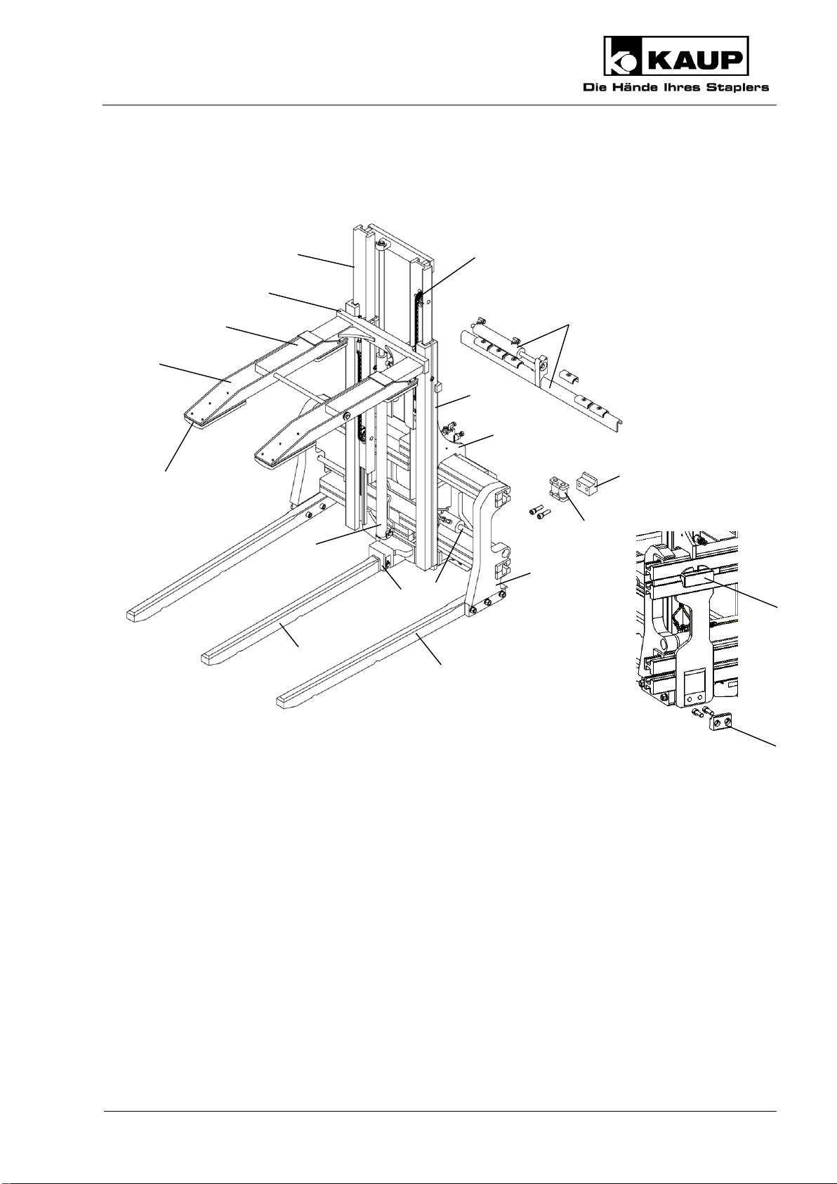
3. Design ...................................................................................................................................................... 7
3.1 Proper use of the equipment.................................................................................................... 8
3.2 Improper use............................................................................................................................ 8
4. Installation and checking out ................................................................................................................ 8
4.1 Installation................................................................................................................................ 8
4.1.1 Drum clamp with sideshift............................................................................................ 9
4.1.2 Drum clamp without sideshift..................................................................................... 10
4.2 Checking out .......................................................................................................................... 11
4.2.1 Bleeding the hydraulic system................................................................................... 11
4.2.2 Adjustment after putting into service ......................................................................... 12
5. Operation ............................................................................................................................................... 13
5.1 General................................................................................................................................... 13
5.2 Load handling......................................................................................................................... 14
5.3 Driving.................................................................................................................................... 14
6. Maintenance and servicing.................................................................................................................. 14
6.1 General................................................................................................................................... 14
6.2 Significant modification .......................................................................................................... 15
6.3 Schedule for routine maintenance and lubricants.................................................................. 16
6.3.1 Pressure plate............................................................................................................ 16
6.3.2 Load stabilizer............................................................................................................ 17
6.3.3 Clamp......................................................................................................................... 18
6.3.4 Mounting with sideshift .............................................................................................. 20
6.3.5 Mounting without sideshift ......................................................................................... 22
6.3.6 Chain adjustment and maintenance.......................................................................... 23
6.3.7 Identification plate and caution board........................................................................ 25

Operating Manual
Original Operating Manual
3
7. Troubleshooting.....................................................................................................................................26
8. Disposal..................................................................................................................................................28
9. Transport ................................................................................................................................................28
10. Decommissioning and storage ............................................................................................................28
11. Spare parts list (not part of the Operating Manual) ...............................................................................28
12. EC Declaration of Conformity (Summary)...........................................................................................28
Our service department in Aschaffenburg will be happy to answer your technical questions and to provide additional support.
Technical Support:
0049 (0)6021 865 395
0049 (0)6021 865 284
0049 (0)6021 865 352
Orders for spare parts Domestic
0049 (0) 6021 865205
0049 (0) 6021 865251
Orders for spare parts Export
0049 (0) 6021 865344
0049 (0) 6021 865348
Outside of normal business hours the Kaup –Service Hotline is available to you 365 days a year:
0049 (0) 172 6295 297
Monday - Friday: 17:00 –7:00 Uhr
Saturday und Sunday: 8:00 –18:00 Uhr
www.kaup.de

Operating Manual
4
Original Operating Manual
1. Introduciton
1.1 Working with this manual
This operating manual contains important information on how to operate the attachment properly,
safely and efficiently.
The operating manual shall be read, understood and applied by all personnel working on or with the
equipment, for example:
Installation and operating the equipment
Inspection, maintenance and repair
Transport and disposal
The manual must be kept available for ready reference at the equipment’s place of use.
The illustrations in this operating manual may deviate from the actual version
of the equipment.
1.2 Warning notes and symbols
The following symbols are used in this operating manual to highlight details of special importance:
Identifies details relating to do’s and don’ts for the purpose of avoiding injury
and property damage.
Specific details relating to the efficient use of the attachment and other advice.
Lists are denoted by a shadowed box.
Steps to be performed by the operator are denoted by a black dot.
(1)
In illustrations, particular elements have numbered pointers. Numbers in brackets in
the text refer to the corresponding elements.
1.3 Copyright
This documentation including all parts is copyrighted. Any use or change outside the narrow limits of
copyright law without permission from KAUP GmbH & Co KG is forbidden and liable to prosecution.
This applies, in particular, to reproduction, translation, microfilming as well as storage and
processing in electronic systems.

Operating Manual
Original Operating Manual
5
1.4 CE-Mark
KAUP-Attachments carry the CE-mark. The EC Declaration of Conformity ensures that the
attachment conforms to the EC machinery guideline.
1.5 Qualified and authorised personnel
Qualified and authorised personnel are equipped by way of their education and training to perform
the tasks assigned to them in accordance with accepted practice and safety regulations. They are
assigned tasks by the equipment owner.
1.6 Warranty claims based on defects
KAUP shall not be liable for any damage to the equipment resulting from:
Improper use / operation.
Modifications to components.
Inappropriate installation, maintenance, inspection and servicing.
Assignment of unqualified or non-authorised personnel.
Claims raised by third parties.
1.7 Limits of applicable use
KAUP-attachments are intended for use under the following climatic conditions:
Average ambient temperature for continuous operation:
+25°C
Allowable maximum ambient temperature, short term (up to 1h):
+40°C
Allowable minimum ambient temperature for attachments intended for
indoor use:
+5°C
Allowable minimum ambient temperature for attachments intended for
outdoor use:
-20°C
Standard models of KAUP-attachments are NOT suitable for:
Use in cold storage facilities.
Use in explosive environments.
Use in conjunction with hydraulic systems involving biological oils.
Use in rough environmental conditions (e.g. seawater)
The transport of acidic liquids.

Operating Manual
6
Original Operating Manual
2. Safety aspects
As the user, extend the safety instructions with generally applicable, legal and other
measures that ensure a safe and environmentally friendly operation of the
attachment.
Pay close attention to all safety- and danger-related signs on the attachment and in
this operating manual. Failure to observe these can result in severe injury or even
death.
Pay close attention to the operating manual provided by the manufacturer of the fork
lift truck.
Keep a safe distance away from moving, reciprocating or rotating parts of the
attachment to avoid danger of crushing, pinching or entanglement.
Notify the responsible department/person immediately of changes and faults in
operation of the attachment that affect safety.
The attachment shall be shut down.
Use aids to vision (e.g. mirrors, camera, etc.) where goods being transported obstruct
vision.
Only allow work on the attachment to be carried out by qualified and authorised
persons. Adhere to the legal minimum age in the country of operation!
The attachment should only be used for the purpose intended.
Never work on or with attachments while under the influence of drugs, alcohol or
medicines which affect reaction time.

Operating Manual
Original Operating Manual
7
3. Design
A beer keg clamp consists of a clamping body (1) on which slides with sliders (2) are moved with
hydraulic cylinders (3). Outer forks (4) are bolted to these slides. A middle fork (5) is inserted into a
mounting (6) and secured with a pin and linch pin. The load stabiliser consists of an outer frame (7)
that is welded to the clamping body (1).
A middle frame (8) is operated by a hydraulic cylinder (9) which then moves the inner slide (11) with
a chain (10). A pivoting pressure plate (13) is attached to the arm (12). This pressure plate (13) has
replaceable rubber elements (14). For sideshift versions, the beer keg clamp is installed to the fork
carriage using upper sideshift elements (15), roller bearing supported spacers (16), and lower hooks
(17), or for the no-sideshift versions, welded-on fork hooks (18) and bolted lower hooks (19) are
used.
15
11
2
1
with sideshift
3
4
5
9
7
8
6
10
12
13
14
17
16
without sideshift
18
19

Operating Manual
8
Original Operating Manual
3.1 Proper use of the equipment
The beer keg clamp is suitable for taking beer kegs of differing sizes with three forks in two rows,
and to stack and transport them. Multiple layers on top of each other can be transported using
locator boards and a load stabiliser. Taking only one row or one keg on the tip of the forks can be
approved with reduced hydraulic pressure. Make enquiries of the beer keg clamp manufacturer.
Goods can also be transported on pallets.
Proper use of the machine and/or equipment includes the following:
Observance of the operating manual at all times.
Observance of the technical data on the identification plate on the attachment.
Adherence to the specified inspection and maintenance instructions.
3.2 Improper use
Exceeding the allowable load capacity and load centre.
Dragging or pushing loads with the attachment
Transporting persons with the load or load handling devices
Mounting auxiliary equipment on the attachment such that the original mode of usage
is changed, (e.g. fork extensions) must be authorised by the manufacturer.
4. Installation and checking out
4.1 Installation
Installation and commissioning should be performed by qualified and authorised
personnel only.
Pay attention to a sufficient load-carrying capacity of the lifting means.
The following are examples of preferred lifting means:
Capacity
250 kg/M16
1200 kg/M16
2000 kg/M16
Part-no.
9710160008
0360010201
0360010301

Operating Manual
Original Operating Manual
9
4.1.1 Drum clamp with sideshift
Hoist the attachment at the position indicated (1).
Demount the lower hooks (2).
Mount the attachment on the fork carriage of the lift truck (3).
Check that the attachment is correctly seated in the centre lock (4).
Ensure correct seating of the spacers (7).
Mount the lower hooks (2), tightening the screws (5) with a torque of 190 Nm.
Connect the hose lines (6) to the hydraulic connectors on the lift truck.
1
2
3
4
7
5
6
6

Operating Manual
10
Original Operating Manual
Trucks equipped with attachments which hold the load by power (e.g. paper clamp) shall
feature control(s) with a secondary action to prevent unintentional release of the load. Also
take note in this respect of the operating instruction of the lift truck.
Before initial operation, check the functions and the identification of the attachment with the
movement directions of the operating elements (operating lever, joystick, etc.).
Mount the residual carrying capacity notice and identification of the operating elements (if
not already present) of the combination of lift truck/attached equipment on the lift truck.
4.1.2 Drum clamp without sideshift
Hoist the attachment at the position indicated (1).
3
3
1
4
5
6
6

Operating Manual
Original Operating Manual
11
Demount the lower hooks (2).
Mount the attachment on the fork carriage of the lift truck (3).
Check that the attachment is correctly seated in the centre lock (4).
Mount the lower hooks (2), tightening the screws (5) with a torque of 190 Nm.
Connect the hose lines (6) to the hydraulic connectors on the lift truck.
Trucks equipped with attachments which hold the load by power (e.g. paper clamp) shall
feature control(s) with a secondary action to prevent unintentional release of the load. Also
take note in this respect of the operating instruction of the lift truck.
Before initial operation, check the functions and the identification of the attachment with the
movement directions of the operating elements (operating lever, joystick, etc.).
Mount the residual carrying capacity notice and identification of the operating elements (if
not already present) of the combination of lift truck/attached equipment on the lift truck.
4.2 Checking out
KAUP-attachments are delivered pre-lubricated. If the attachment has been in storage
for a longer period, we recommend that it be lubricated again before being placed in
service. See 6. Maintenance and onwards.
Failure of the safety devices (e.g. the pressure relief valve and the non-return
valve) and incorrect connection of the controls to the actuators can cause
malfunctioning of the attachment and damage to it.
After mounting and before initial operation, check the functions and the
identification of the attached equipment with the movement directions of the
operating elements (operating lever, joystick, etc.).
4.2.1 Bleeding the hydraulic system
Start the lift truck.
Move the sideshifter repeatedly in both directions to maximum extent.
Repeatedly cycle fork positioner from the fully open to the fully closed position.
Inspect the hydraulic connections for leakage.

Operating Manual
12
Original Operating Manual
4.2.2 Adjustment after putting into service
The hydraulic system is under pressure. During work on hydraulic components
oil spurting out can cause injuries. Unload the system in accordance with the
operating instructions of the lift truck manufacturer. In the case of injuries
caused by high pressure oil, inform the works physician and seek out a
specialist immediately.
Synchronising the arms
The synchronization of arms is adjusted ex-factory. This can alter for different friction
conditions (wear), temperatures and volumes conveyed. Perform a readjustment. The
recommended working temperature of the hydraulic fluid is approx. 35 °C.
The synchronisation or speed of the cylinders can be set with two valves on the cylinder bottoms.
X
Setting the clamping pressure with a pressure limiting valve
Attachments are adjusted ex-factory to a pressure of 160 bar.
A change in pressure is necessary only, if the load
slips or
is damaged.

Operating Manual
Original Operating Manual
13
Make the settings in the numerical sequence and in the direction of the arrows.
The pressure indication on the manometer gauge drops after clamping.
This is not a malfunction of the attachment, being caused by the installation of a
transmission
5. Operation
5.1 General
At least once per working shift, the machine and equipment must be inspected for
visible damage and defects.
Repeat faults to your superior and have them rectified without delay.
Be aware of persons present in the area where you are working or driving and ensure
that they are not endangered.
Do not transport any load exceeding that specified on the residual load plate for the
particular combination of lift truck and attachment.
Operate the sideshifter only with the load raised freely (10 cm).
Close the load stabiliser to its smallest position for an empty run.
Ensure that fork arms and arms that clamp a load are closer together at the tips than
at the back. As a result you need a larger clearance for moving in.

Operating Manual
14
Original Operating Manual
5.2 Load handling
Set the forks to the necessary opening range for the size of the kegs.
Position the mast vertically and take up the load parallel to the floor. Move in the
direction of the drums as far as possible.
Only transport stable drums.
Raise the load about 300 mm and tilt the mast backwards.
Centre the load to the middle of the lift truck during take-up and transport.
5.3 Driving
Ensure that the drums and pallets are in a proper state.
Use a load stabiliser to secure the load when moving multiple layers.
Do not drive with the mast tilted forward.
Take care when driving that neither the attachment nor the load comes into contact
with the ground.
Driving with the load stabiliser opened may cause damage to supporting components.
During driving, make sure that the load stabiliser either abuts on the load or is closed
completely.
6. Maintenance and servicing
6.1 General
Regular maintenance is essential to ensure reliable operation and long service life of the KAUP
attachment.
Ensure that maintenance and servicing are performed by qualified and authorised
personnel only.
Lubrication and cleaning work on the attachment may also be performed by the lift truck
operator.
Perform maintenance and servicing work only when the attachment is parked securely
on a stable, level foundation. For installing and removing, it is recommended to use a
pallet to take the attachment. The attachment can thus be securely placed and
transported.
Pay attention to a sufficient load-carrying capacity of the lifting means.

Operating Manual
Original Operating Manual
15
Replace missing or defective warning signs on the attachment.
Do not use third party spare parts. Through poor quality or incorrect matching
they can result in a risk of accident. The EC Declaration of Conformity by the
manufacturer becomes invalid and you assume full responsibility in the case of
accident.
Use only original spare parts from the manufacturer.
The hydraulic system is under pressure. During work on hydraulic components
oil spurting out can cause injuries. Unload the system in accordance with the
operating instructions of the lift truck manufacturer. In the case of injuries caused
by high pressure oil, inform the works physician and seek out a specialist
immediately.
Screw connections can loosen due to vibration of the attachment. During routine
maintenance check that screw connections are correctly torqued and replace
screws which are visibly damaged.
Note the following tightening torques which are valid for screws with connecting surfaces according
to ISO 4762, ISO 4014, ISO 4032 etc.:
Screw/bolt rating
8.8
10.9
12.9
M6 thread
9,3Nm
14Nm
16Nm
M8 thread
23Nm
33Nm
39Nm
M10 thread
45Nm
66Nm
77Nm
Μ12 thread
77Nm
115Nm
135Nm
Μ16 thread
190Nm
280Nm
330Nm
Μ20 thread
385Nm
550Nm
640Nm
Failure of the safety devices (e.g. the pressure relief valve and the non-return
valve) and incorrect connection of the controls to the actuators can cause
malfunctioning of the attachment and damage to it.
After mounting and before initial operation, check the functions and the
identification of the attached equipment with the movement directions of the
operating elements (operating lever, joystick, etc.).
6.2 Significant modification
Significant modifications are, for example, those which affect the stability, performance, speed and
strength of components.
The EC Declaration of Conformity is invalidated by a significant modification of the attachment.
Modifications to the attachment may only be made with prior approval by the manufacturer.

Operating Manual
16
Original Operating Manual
6.3 Schedule for routine maintenance and lubricants
Lubricants approved and recommended by KAUP
Greases
Note
Lithium soap grease
NLGI Class 2
e.g. Avialith 2
Designation DIN51825:
K 2 K-30
Complex soap grease
NLGI Class 2
e.g. Turmogrease Gel M 5
Foundry quality
Teflon spray
e.g. Wieds or Rivolta
Only for plastic sections
The specified maintenance schedules can change as a result of the operating conditions
such as extreme cold, heat and dust or poor ground conditions and this must be taken
into account by the owner.
With other loads, such as fork arms with a length of over 2,400 mm or raised load
centres, amended/shorter maintenance intervals should be agreed by the user with the
manufacturer.
6.3.1 Pressure plate
Daily
Ensure that the screw (1) with plain washers (10) is mounted and tightened. This
screw is used as a limit stop and prevents uncontrolled moving out of the slide (2).
As necessary
Renew worn pressure plate linings (3) or damaged pressure plates (4) by removing
the screw (5) and washer (6) on the bearing pin (7). Pull the bearing pin (7) out to the
side. Demount screw (9) with washer and replace worn or damaged parts.
Afterwards, mount the screws (9) with washer, and bearing pin (7) with washers (6, 8)
and screw (5).
7
8
5
6
1
10
2
4
9
3

Operating Manual
Original Operating Manual
17
6.3.2 Load stabilizer
41, 26
23, 27
41
5
10
11
2
3
18
22
4
24
20
19
21
25
13
16
1
12
23
32

Operating Manual
18
Original Operating Manual
6.3.3 Clamp
Daily
Check all lines, hoses and connections for leakage and damage.
After 50h / every 500h thereafter
Check screws
(1) on the slide (2).
(3) on the picket (4) and clamping body (5).
(6) and nuts (7) on the forks (8) and slide (9).
Replace loose or damaged screws. Torque the screws as specified in Chapter 6.1
General.
6
7
8
9
26
27
30
31
34
35
39
38
40
37
5
29
28
15
14
36

Operating Manual
Original Operating Manual
19
Weekly
Grease:
Sliding pieces (10) by way of the greasing nipples (11).
Sliding pieces (12) by way of the greasing nipples (13).
Sliding pieces (14) by way of the greasing nipples (15).
Every 200h
Check wear on:
Sliding pieces (10, 12, 14).
As necessary
Renew worn sliders (10) by removing the screws (3) for the chain mount (4) on the
clamping body (5). Demount the nut (22) on the cylinder (23) and pull the middle
frame (24) with the slide (2) upwards out of the clamping body (5). Remove the
grease nipple (11) and screw (18) and replace slider (10). Remount the screw (18)
with grease nipple (11) and place the middle frame (24) and slide (2) into the
clamping body (5) from above. Connect the nut (22) with the cylinder (23) and secure
the chain mount (4) with the screw (3) onto the clamping body (5).
Renew worn sliders (12) by removing the screw (1) and washer (16). Demount the
screw (19), bush (20), pressure spring (21) and lock nut (22) on the slide (2). Pull the
slide (2) upwards out of the middle frame (24). Demount the grease nipple (13), bolt
(25) and replace slider (12). Remount the screw (25) with grease nipple (13) and
place the slide (2) into the middle frame (24) from above. Connect the screw (19),
bush (20), pressure spring (21) and lock nut (22) to the slide (2). Ensure that the
screw (1) and washer (16) is mounted on the slide (2).
Renew worn sliders (14) by removing the nuts (26) of the cylinder (27). Pull the slide
(9) out of the clamping body (5) to the side. Demount the grease nipple (15), screw
(28) and replace slider (14). Ensure correct seating of the axial retainer (29) during
installation of the new sliders. Mount the scrwe (28) and grease nipple (15) and push
the slide (9) into the clamping body (5). Remount the nuts (26) of the cylinder (27).
Renew defective cylinders (23) by removing the screw (3) for the chain mount (4) on
the clamping body (5). Demount the nuts (41) on the cylinder (23) and pull the middle
frame (24) with the slide (2) upwards out of the clamping body (5). Replace the
defective cylinder (23). Place the middle frame (24) and slide (2) into the clamping
body (5) from above. Connect the nut (41) with the cylinder (23) and secure the chain
mount (4) with the screw (3) onto the clamping body (5).
Renew the defective cylinder (27) by removing the nuts (26) of the cylinder (27). Pull
the slide (9) out of the clamping body (5) to the side. Replace the defective cylinder
(27) and push the slide (9) into the clamping body (5). Remount the nuts (26) of the
cylinder (27).
After installing or removing a cylinder (23, 27), always check the clearance between
the cylinder mount (32) and nut (41, 26) of the cylinder (23, 27). Cylinders are
installed with axial clearance of 1.5 to 2 mm.

Operating Manual
20
Original Operating Manual
Replace worn forks (8) by demounting screw (6), washer (31) and nut (7). Replace
worn forks (8) and mount bolt (6), washer (31) and nut (7). Ensure that the bushes
(30) are present.
Replace wear plates (33) by removing bolt (6), washer (31), nut (7), and bushing (30)
of the fork (8). Remove bolt (32) in slide (9), and replace wear plate (33). Reinstall
bolt (32), bushing (30), fork (8), bolt (6), washer (31), and nut (7). Ensure that the
bushes (30) are installed.
Replace wear plates (39) by removing the linchpin (34) of the pin (35) from the fork
(36). Pull the pin (35) out to the side and the fork (36) to the front of the support (37)
of the clamping body (5). Remove screw (38) and pin (40) and replace wear plate
(39). Reinstall screw (38) and pin (40), insert the fork (36) into the support (37) of the
clamping body (5) from the front, insert the pin into the fork (36) from the side, and
secure it using the linchpin (34).
Take forks out of service if the wear represents more than 10 % of the original
thickness of the fork.
Deformed forks are not safe to operate and must be excluded from further use.
Truing the forks may only be undertaken by the manufacturer of the forks or by a
company authorised by the manufacturer.
6.3.4 Mounting with sideshift
1, 12
8
7
11
6
4
5
10
9
1
3
8
12
2
This manual suits for next models
1
Table of contents
Other KAUP Forklift manuals