Big Sprinkler 1000R User manual
15250 W. Sunshine Road | Yukon, OK 73099 | 1-855-805-7901
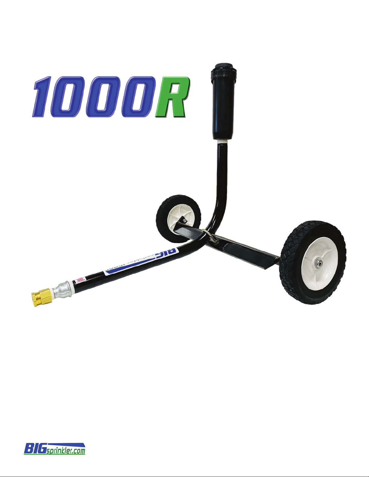
Thank you for purchasing the 1000R Wheeled Sprinkler Cart from BigSprinkler.comTM. This sprinkler cart
is an excellent and affordable option for irrigating a variety of areas such as a small or large lawn, gardens,
playgrounds, natural and artificial sports fields, horse arenas or round pens for dust control, and much
more. Our carts are fabricated with care and precision in our Yukon, Oklahoma facility with quality heavy
duty components.
The following manual is a guide for assembly, setup, and operation of your new BigSprinklerTM cart. Please
read and follow all instructions carefully.
We also offer accessories such as 3/4” garden hoses, larger pre-made hose kits with quick connects for
easy hook-up and booster pumps that will greatly enhance pressure and performance for your sprinkler cart.
1000R Wheeled Sprinkler Cart
Cart Assembly Instructions
Please read this manual carefully and follow all safety and assembly instructions below to ensure that your
cart is assembled correctly and operates properly upon start-up. If you have any questions please call 855-
805-7901.
Safety
Safety is the main priority and failure to follow these instructions may cause serious injury. BigSprinkler.com is not responsible for product failure,
property damage, or personal injury if these procedures and operation instructions are not followed.
•Beware of electric power lines
Irrigation water should never contact electric power lines or any other power source. Never let
any part of the sprinkler cart or any irrigation fittings or pipe come in contact with an electric
power source.
•Use caution up close to operating sprinkler heads
Pressurized water from the sprinkler head could cause serious damage to people or objects.
Never allow small children to play close to operating sprinkler heads!
!!
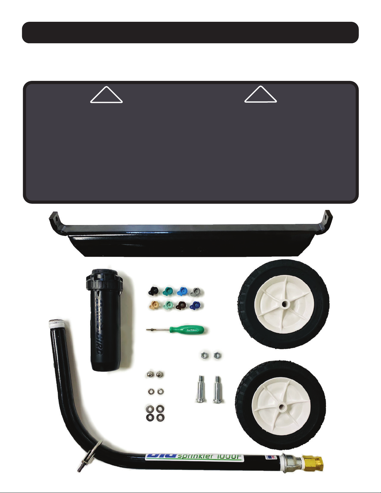
(2) Wheels – 8”
Rotor Sprinkler 1”
(#4 thru #18 Nozzles included)
Screw Driver
1/4”
(4) Flat Washers
5/16”
(2) Lock Nuts
3/8”
(2) Shoulder Bolts
3/8”
(2) Acorn Nuts
1/4”
Sprinkler Cart Axle
Sprinkler Cart Body
(2) Lock Washers
5/16”

Cart Assembly Instructions
STEP 2) MOUNTING WHEELS ONTO THE AXLE
Place the shoulder bolt through the middle on the front side of the wheel as shown in the image. Next,
continue to pass the threaded end through the hole at the end of the axle tab. To secure the wheel,
thread the 3/8” lock nut on the end of the bolt and tighten with a 9/16” wrench and the provided 1/4”
Hex Tool. Tighten until it stops. Repeat the same steps for the other wheel.
STEP 1) BODY & AXLE ASSEMBLY
First, assemble the axle to the main body. Place (1) flat washer on each of the threaded ends of the u-
bracket on the body. Next, align and insert the threaded ends of the u-bracket on the main body through
the 2 holes in the axle. Then, secure the axle to the body by placing (1) flat washer, (1) lock washer and (1)
1/4” acorn nut on each of the threaded ends. Tighten using a 9/16” wrench.
NOTE: Do not adjust the u-bracket mounted on the body. It is properly preset from the factory.
Front Side Back Side
123
4 5 6
U-Bracket
U-Bracket
Finished Body & Axle Assembly

STEP 4) Position sprinkler cart in area to be watered and attach cart to your hose. Your sprinkler cart is
now ready for operation. NOTE: Always run water through your garden hose to flush out before hooking it
up to your sprinkler cart. Doing so will prevent anything from clogging the sprinkler when running.
To make adjustments to the impact sprinkler please refer to the “Impact Sprinkler Adjustment” page.
Cart Assembly Instructions
STEP 3) INSTALLING THE IMPACT SPRINKLER HEAD
First, remove the thread protector cap to expose the taped threads, do not remove white thread tape.
Place the bottom of the sprinkler on top of the threads and slowly turn clockwise. NOTE: Make sure to begin
slowly so that the threads start correctly. If they are cross threaded, it will result with the threads being
damaged on both the cart and sprinkler.
Secure sprinkler head by tighteningwith a large enough crescent wrench or pipe wrench. CAUTION: Only
tighten sprinkler head by placing wrench on the lower base area of the sprinkler head to avoid damage to
the upper portion of the sprinkler.
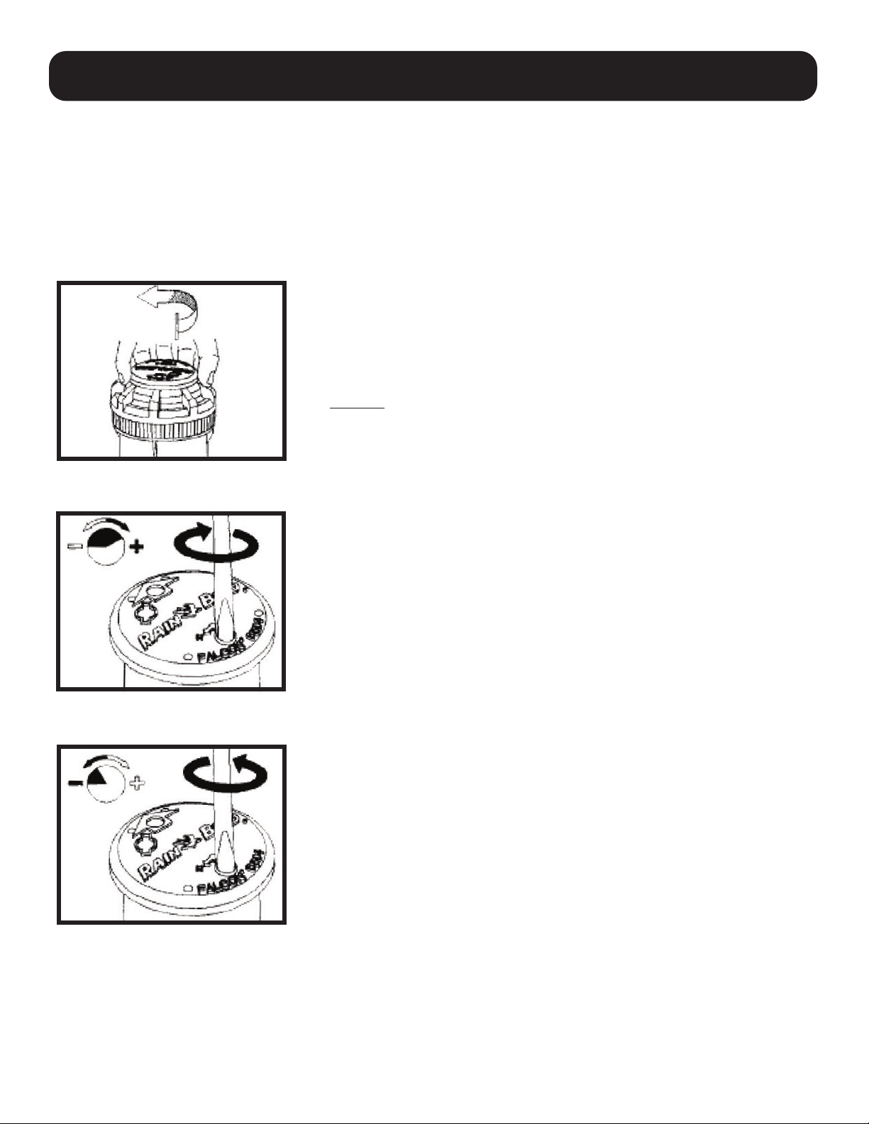
Arc Adjustment
The arc is adjustable from 400- 3600(PC units only). All part-circle
Falcon 6504 rotos are factory preset to approximately 180 degrees.
It can be adjusted from the right trip. The left trip is fixed.
Align Fixed Left Trip (A)
1. Pull up turret and turn the left trip point (counterclockwise).
Caution: If the rotor does not turn easily, first turn it right,
(clockwise) to the right trip point.
2. Next, turn the turret until the arrow points in the
direction you want to set the left edge trip.
To Increase the Arc (B)
1. While holding the nozzle turret at the fixed left stop, insert tool or
screwdriver into the adjustment socket.
2. Turn the screwdriver counterclockwise (+) to increase
the arc.
3. Each full turn of the counterclockwise turn of the
screwdriver will add 45 degrees of arc.
4. When the maximum arc of 360 degrees has been set, you will feel
some resistance in the adjustment screw. Do not adjust the rotor
beyond the maximum arc.
To Decrease the Arc (C)
1. While holding the turret at the fixed left stop, insert tool or
screwdriver into the arc adjustement socket.
2. Turn the srewdriver clockwise (-) to decrease the arc.
3. Each full clockwise turn of the screwdriver will remove 45
degres of arc.
4. When the minimum arc of 40 degrees has been set, you will feel
some resistance in the adjustment screw. Do not adjust the rotor
below the minimum arc.
(if ordered with part circle sprinkler)
A
B
C
Arc Adjustment
NOTE: The internal spring has been removed in order for the Rotor head to
operate with lower pressures. This will not change the sprinklers performance.

Arc Adjustment Slot
Arc adjustment slot—Only on part circle models
Pull Up Slot—Insert
rotor tool here and
turn 90 degrees
to pull stem up and
change nozzle size.
Nozzle Retainer Screw which also acts
as the radius adjustment to diffuse the
spray pattern and decrease sprinkler
throw.
CAUTION: Always use black plastic hold
up tool when changing nozzles. Hold
up tool will snap into the riser stem to
hold it in an extended position while
performing nozzle changes.
Nozzle Installation (D & E)
1. Insert the Pull up Tool into the pull-up slot, turn 90 degrees and lift up stem.
Clip the black plastic hold up tool onto the riser to support the riser in this
extended position.
2. Loosen the nozzle retainer screw until it no longer
obstructs the nozzle opening in the nozzle housing.
3. To remove the nozzle, insert the flat-head of the rotor tool supplied into the
lower right side of the nozzle to pry it loose.
4. To re-install a nozzle, insert the color coded nozzle firmly into the
opening until it is flush with the nozzle turret.
5. Tighten the nozzle retainer screw (which also acts as the radius
adjustment to decrease sprinkler throw) clockwise to secure
the nozzle. The screw threads must engage the nozzle surface
to ensure proper seating of the nozzle and hold it in place during
operation.
D
E
Falcon Rotor Sprinkler Head Settings
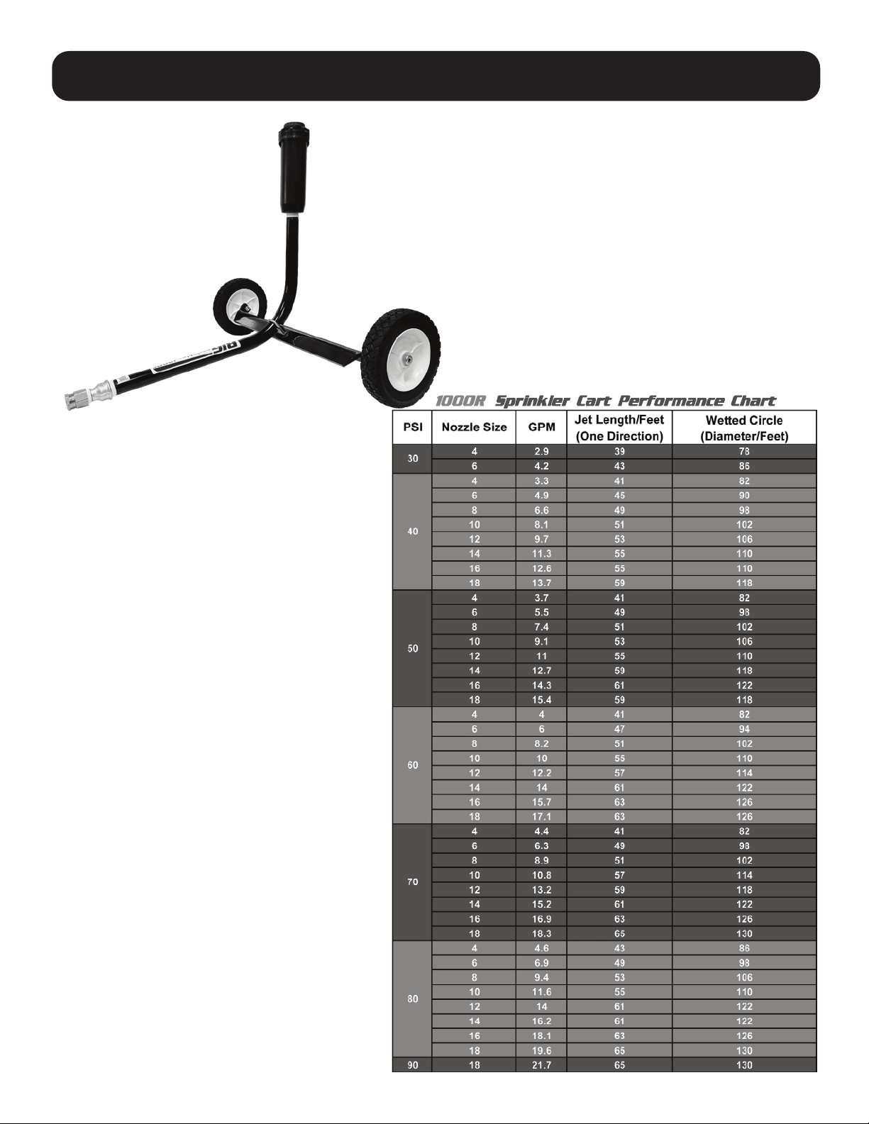
Notice: These
specifications are to be
used as a guide only and
have been calculated at
zero wind conditions.
Performances can
vary due to pressure,
terrain, wind, and field
conditions.
1000R Sprinkler Cart Chart

LIMITED WARRANTY AND REMEDY:
WARRANTY
BigSprinkler.comTM warrants to the original purchaser only of the products described in the face hereof
as of the date of the original invoice, that the product is merchantable and free from defects in
material and workmanship.
Warranty shall be provided by the original manufacturer of products sold on BigSprinkler.comTM for the
length of time specified by the manufacturer of the given product.
Sprinkler stands - 1 year
Sprinkler heads - 1 year
REMEDY
If BigSprinkler.comTM determines that the above warranty was breached with respect to any part or
component provided by the manufacturer of the product (and if all conditions set forth below have
been satisfied) then, BigSprinkler.comTM will (at BigSprinkler.comTM ’s option) provide purchaser a refund
of the purchase price less the freight costs to or from the customer, or provide a replacement product
of the same kind.
All remedies provided herein are for goods only, no labor or freight allowance for return goods is
implied.
This warranty extends only to the original purchaser of products purchased from BigSprinkler.comTM.
CONDITIONS TO ENFORCEABILITY AND CLAIMS:
1. Product has been maintained and operated within the guidelines outlined in the manufacturer’s
product guide and maintenance manual.
2. Product warranty shall be considered void if any component or function of the equipment has
been altered in any form other than what has been provided or intended by the original product
manufacturer.
3. Any return must be submitted on form provided by BigSprinkler.comTM in writing immediately and
in no event longer than 20 days from occurrence. You can reach our sales department through the
“contact us” form on our website should such an event occur.
4. Purchaser must return all goods within 30 days of BigSprinkler.comTM ’s authorization date, that
have been determined by BigSprinkler.comTM to be defective to the Purchaser with Purchaser being
responsible for freight.
LIMITATIONS:
BigSprinkler.comTM or it’s affiliates shall not be liable for any incidental or consequential damages
(including but not limited to, damages for injury to the person, property or lost turf, crops or profits)
by reason of any defect in the products sold or its manufacture, design, or function.
Warranty
Table of contents
Popular Irrigation System manuals by other brands


Senju Sprinkler
Senju Sprinkler HF-RES quick start guide

Tyco Fire Protection Products
Tyco Fire Protection Products CC2 manual

wesmartify
wesmartify essentials Smart Garden operating instructions

Tyco
Tyco EC-11 Series manual

Parkside
Parkside PTBS 30 A1 operating instructions

SNOWJOE
SNOWJOE AquaJoe AJ-IS10WB instructions

Rain
Rain SuperPro S075 S Setting instructions

Reliable
Reliable DH56 Dry installation instructions

Viking
Viking VK290 Technical data

Underhill
Underhill Mirage M-125 Operating and maintenance instructions

Tyco Fire Product
Tyco Fire Product CENTRAL ESFR-17 instruction manual

Fiskars
Fiskars 1027028 Original instructions