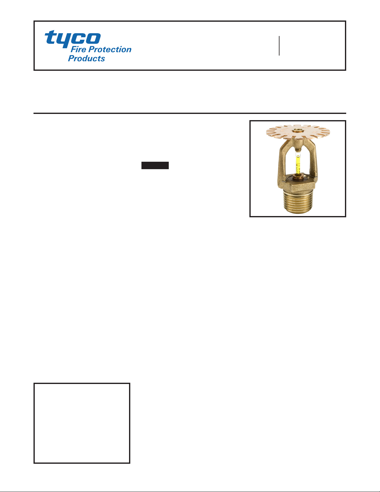
TFP632
Page 3 of 8
cal Manual” must be met. When using
1 inch (DN25) or larger pipe, a hanger
must be located at the truss nearest a
sprig for purposes of restraint. If using
3/4 inch (DN19) piping, all sprigs over
12 inches (305 mm) must be laterally
braced using methods described in
the NFPA standards.
Where the CPVC must be offset up
and over an obstruction and the pipe
exceeds the allowed horizontal posi-
tioning requirements specified above
as well as shown in Figure 2 and 3, ad-
ditional Model CC2 Sprinklers are to
be installed as shown in Figure 2 and
3 to protect the BlazeMaster CPVC
product.
A minimum lateral distance of 18
inches (460 mm) must be maintained
between the CPVC pipe and heat
pumps, fan motors, and heat lamps.
Steel Pipe
CC2 Temperature Rating (Steel
Pipe)
175° F (79° C)
Area Of Use (Steel Pipe)
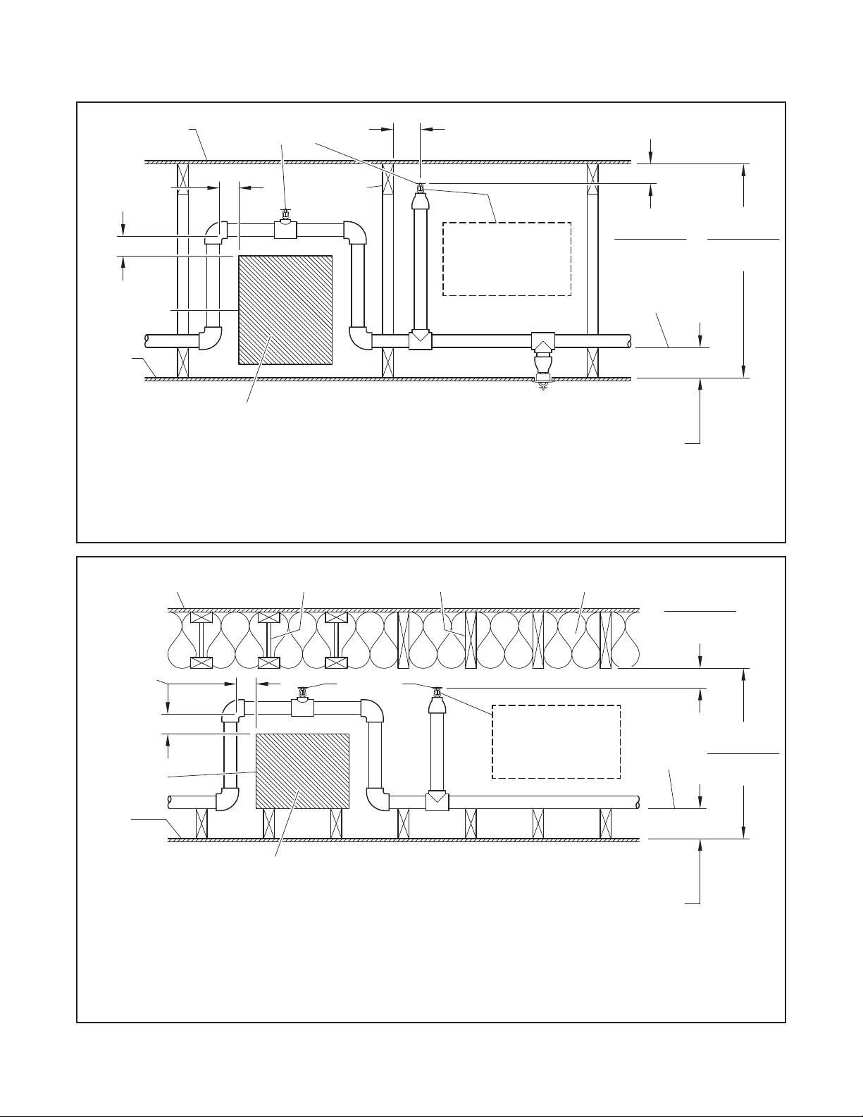
Horizontal (slope not exceeding 2:12)
combustible concealed spaces of
•
Unobstructedwoodtrussconstruc-
tion or unobstructed bar joist
construction(Fig.4)
•
Solidwoodjoistconstruction(Fig.
5)wheretheupperdeckandceiling
joistsmayhaveamaximumdepth
of12inches(300mm)andtypical
oncenterjoistspacingofminimum
16inches(400mm)
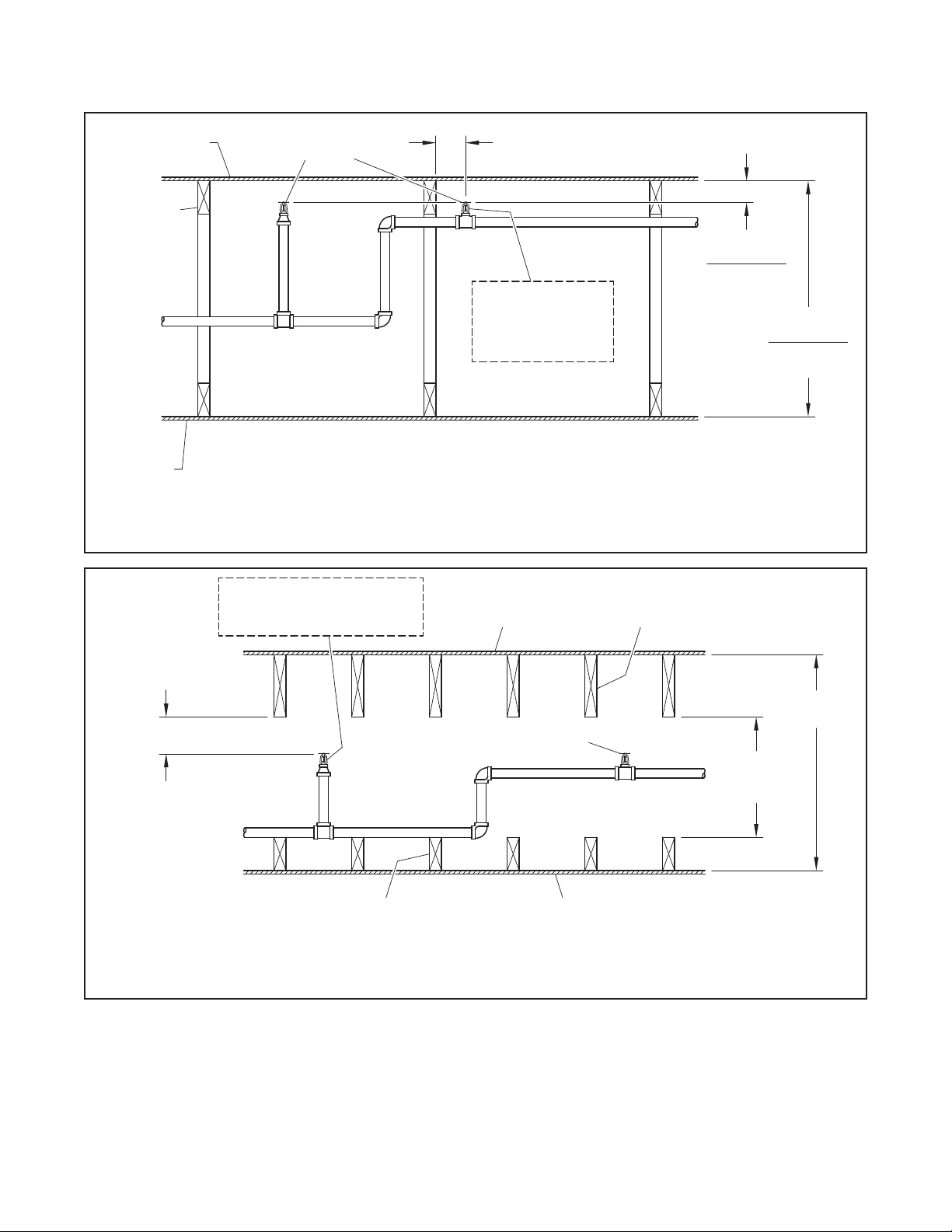
•
Non-combustible insulation lled
solidwoodjoistorwoodcomposite
joistconstruction(Fig.6)
•
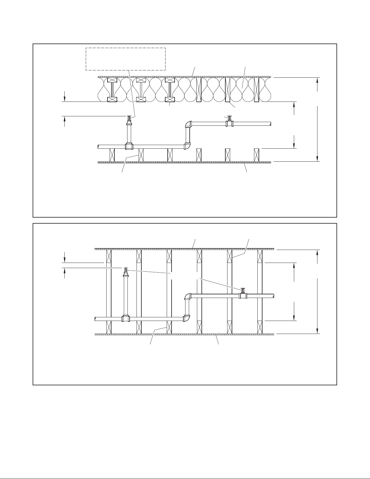
Obstructedwoodtruss construc-
tion(Fig.7)
NOTE: In order to be considered
“non-combustible insulation filled sol-
id wood joist or composite wood joist
construction”, the insulation (including
insulation provided with a combusti-
ble vapor barrier),must completely fill
the pockets between the joists to the
bottom of the joists, and the insulation
must be secured in place with metal
wire netting. The metal wire netting is
intended to hold the insulation in place
should the insulation become wetted
by the operation of the CC2 Sprinklers
in the event of a fire.
Concealed Space Area (Steel Pipe)
The area of the concealed space is
not limited; however,
•
for unobstructed wood truss
constructionorconcealedspaces
ofnon-combustible,unobstructed
bar joist construction (Fig. 4)
draft-curtains or full height walls
must be provided at 1000 ft2 (93
m2)areas.Thisdraft curtainshall
be at least 1/3 the depth of the
concealedspaceor8inches(200
mm), whichever is greater, and
be constructed using a material
that will not allowheat toescape
throughorabovethedraftcurtain.
•
for solid wood joist construction
(Fig.5)andobstructedwoodtruss
construction(Fig.7),blockingmust
beprovidedineachupperdeckand
ceilingjoistchannelatamaximum
32 feet (9,75 m) intervals. This
blockingshallbeinstalledtothefull
depthofthejoistsandbeinstalled
soastonotallowheattoescape
through or above the blocking.
Theblockingmustbeconstructed
usinganon-combustiblematerial
or the joist construction material.
Draftcurtainsmustprotrudebelow
thejoistaminimumof6inches(150
mm) or 1/3 the space, whichever
is greatest, and run parallel with
thejoistspacedat31feet(9,4m)
widthmaximumtolimittheareato
amaximumof1000ft2(93m2).The
draft curtain may be constructed
of 1/4 inch (6,4 mm) plywood to
preventheatfromescapingbeyond
thearea.
•
For non-combustible, insulation-
lledsolidwoodjoistorcomposite
woodjoistconstruction(Fig.6),the
requirement for draft curtains or
blockingdoesnotapply.
Concealed Space Size (Steel Pipe)
The minimum and maximum con-
cealed space depth is as follows:
For unobstructed wood truss con-
struction or concealed spaces of un-
obstructed bar joist construction (Fig.
4) the depth of the concealed space
is 36 inches (915 mm) maximum to 12
inches (305 mm) minimum.
For solid wood joist construction (Fig.
5), solid wood or composite wood joist
construction filled with non-combus-
tible insulation (Fig. 6), or obstruct-
ed wood truss construction (Fig. 7),
the maximum depth of the concealed
space is 54 inches from bottom of up-
per deck to top of ceiling, and the min-
imum depth is 6 inches from the bot-
tom of the upper deck joists to the top
of the ceiling joists.
System Type (Steel Pipe)
Light hazard, wet or dry pipe system
using steel pipe.
NOTES:
Use of the 4.2K sprinklers in
dry pipe systems is permitted by section
8.3.4.3 of NFPA 13 (2007 edition) where
piping is corrosion resistant or internally
galvanized.
Minimum Distance Between CC2
Sprinklers (Steel Pipe)
7 feet (2,1 m)
Maximum Distance Between CC2
Sprinklers (Steel Pipe)
12 feet (3,7 m)
Maximum Coverage Area (Steel
Pipe)
144 ft2(13,4 m2)
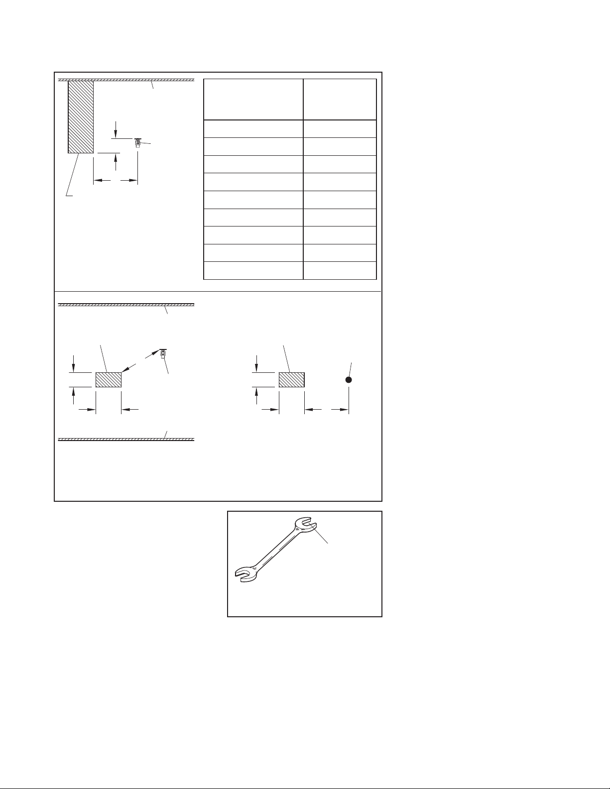
Deflector Position (Steel Pipe)
1-1/2 to 4 inches (40 to 100 mm) be-
low upper deck for wood truss con-
struction or concealed spaces of non-
combustible bar joist construction
(Fig. 4)
1-1/2 to 2 inches (40-50 mm) below
solid wood joist (Fig. 5) or top chord of
a wood truss that has a depth greater
than 4 inches
1-1/2 to 4 inches (40 to 100 mm) below
non-combustible insulation filled solid
wood joists or composite wood joists
(Fig. 6)
Remote Area (Steel Pipe)
The remote area for wood truss con-
struction or bar joist construction (Fig.
4) or solid wood joist construction
(Fig. 5) is 1000 ft2(93 m2) for wet pipe
systems or 1300 ft2(121 m2) for dry
pipe systems.
The remote area for non-combusti-
ble insulation filled solid wood joist
or wood composite joist construction
(Fig. 6) is to be calculated per the re-
quirements of NFPA 13.
Required Density (Steel Pipe)
0.10 gp m /f t 2(4,1 mm/min)
Minimum Operating Pressure (Steel
Pipe)
7 psi (0,48 bar)
Note: The minimum resulting flow for
the 4.2K is 11.1 gpm, and the mini-
mum resulting flow for the 5.6K is
14.8 gpm. Therefore, for coverage ar-
eas less than the maximum permitted
coverage area of 144 ft2, the 4.2K may
provide a hydraulic advantage. The
use of the CC1 sprinkler having a K
factor of 2.8, minimum operating pres-
sure of 10 psi, and resulting minimum
flow of 9.5 gpm may provide a further
hydraulic advantage for yet smaller
coverage areas when designing wet
pipe systems. The CC1 is described in
Technical Data Sheet TFP630.
Obstructions (Steel Pipe)
See Figure 8 in this data sheet for ob-
structions rules.