a. Base Part No. 10485 with 1/2"
(1 5 mm) NPTor
b. Base Part No. 10680 with 3/4"
(20 mm) NPT
To order the Cover Plate Assembly, re-
fer to: Part No. 09804.
NOTE:Specify temperature rating of
sprinklerandtemperatureratingandfin-
ishofcoverplateassembly(seeTable1
on page 58 d).
ACCESSORIES
Sprinkler Cabinet: Part No. 01731A
Capacity: six (6) sprinklers
Available since 1971.
Concealed Sprinkler Wrenches *:
A. Heavy Duty: Part No. 08336W/B
Available since 1993
B. Light Duty: Part No. 10366W/B**
Available since 1998
* A1/2"ratchetisrequired(notavailablefromVi-
king).
** Ideal for sprinkler cabinets.
5. AVAILABILITY AND SERVICE
Viking products are available through a
network of domestic, Canadian, and in-
ternational distributors. See the Yellow
Pagesofthetelephonedirectoryforalo-
cal distributor (listed under “Sprinklers-
Automatic-Fire”) or contact Viking.
Viking Technical Data may be found on
The Viking Corporation’s Web site at:
http://www.vikingcorp.com
The Web site may include a more recent
edition of this Technical Data page.
6. GUARANTEES
For details of warranty, refer to Viking’s
current price schedule or contact The
Viking Corporation directly.
7. INSTALLATION
WARNING: Viking sprinklersaremanu-
factured and tested to meet the rigid re-
quirements of the approving agency.
The sprinklers are designed to be in-
stalled in accordance with recognized
installation standards. Deviation from
the standards or any alteration to the
sprinkler or cover plate assembly after it
leaves the factory including, but not lim-
itedto: painting, plating, coating or mod-
ification, may render the sprinkler inop-
erative and will automatically nullify the
approval and any guarantee made by
The Viking Corporation.
A. Sprinklers must be installed in accor-
dance with the latest published stan-
dards of the National Fire Protection
Association, Factory Mutual, Loss Pre-
vention Council, Assemblee Pleniere,
Verband der Sachversicherer or other
similar organizations, and also with the
provisions of governmental codes, ordi-
nances, and standards whenever appli-
cable. Concealedsprinklers are decora-
tive sprinklers and may be considered
special purpose. Refer to the Authority
Having Jurisdiction prior to installation .
NOTE: Previous Model B-1 Cover Plate
Assembly Part Number 08310 may still be
used for ULC/UL installations .
B. Sprinklers must be handled with care.
Concealedsprinklers areprotected witha
plasticshell,whichshouldremaininplace
overthe sprinkler body during installation,
testing, and any time the sprinkler is han-
dled or shipped. The plastic protective
shellmustberemovedprior toplacing the
systeminservice. Seesection“I”belo w.
Prior to installation, sprinklers must be
stored in a cool, dry place in their origi-
nal shipping container. Never install
sprinklers that have been dropped,
damaged in any way, or exposed to
temperatures in excess of maximum
ambient temperature allowed. Such
sprinklers should be destroyed immedi-
ately .
C. Horizon®Mirage®Quick Response
ConcealedSprinklersmustbeinstalled
in neutral or negative pressure ple-
nums only.
D. U se care when locating sprinklers near
fixtures that can generate heat. Do not
installsprinklerswheretheywouldbeex-
posed to temperatures that exceed the
maximum recommended ambient tem-
peratureforthetemperatureratingused .
E. Horizon®Mirage ®Concealed Sprin-
klers are not intended for use in corro-
sive environments. Use only sprinklers
listed for corrosive environments when
subject to corrosive atmospheres.
F. Adequate heat must be provided when
Horizon ®Mirage®QuickResponse Ex-
tended Coverage Concealed Sprin-
klersare installedon wetpipe systems.
When installing sprinklers on dry sys-
tems, refer to appropriate installation
guides and the Authority Having
Jurisdiction.
G. Sprinklers must be installed after the
piping is in place to preventme chanical
damage. Before installation, be sure to
have the appropriate sprinkler model
and style, with the correct orifice size,
temperature rating, and response char-
acteristics. Install the sprinklers accord-
ing to the following steps :
1. Installallpipingand cutthe sprinkler
drop nipple to position the 1/2" or
3/4" (depending on the sprinkler)
NPT outlet of the reducing coupling
at the desired elevation. The drop
nipple must be perpendicular to the
ceilingand centeredin a2" (50mm)
diameter opening in the ceiling.
2. With the sprinkler in the plastic pro-
tectiveshell,applyasmallamountof
pipe-joint compound or tape to the
external threads of the sprinkler
only, taking care not to allow a
build-up inside the sprinkler inlet .
3. Use only the special wrenches de-
signed for installing Horizon ®Mirage ®
Concealed Sprinklers. With the sprin-
kler in the plastic protective shell,
place the unit into the wrench .
4. Turn the unit clockwise to thread the
sprinkler into the 1/2" or 3/4" (de-
pending on the sprinkler used) NPT
outlet of the coupling. DO NOT use
the fusible link to start or thread the
sprinkler into a fitting.
H.Afterinstallation,theentiresystemmust
be tested in accordance with recog-
nizedinstallationstandards.Thetestis
appliedaftersprinklerinstallationtoen-
sure that no damage has occurred to
thesprinklerduringshippingandinstal-
lation, and to make sure the unit has
beenproperlytightened.Ifathreadleak
occurs, normally the unit must be re-
moved, new pipe-joint compound or
tape applied, and then reinstalled. This
is due to the fact that when the joint seal
leaks, the sealing compound or tape is
washed out of the joint .
I. After testing, repairing of all leaks, and
installation and painting of the ceiling,
the cover plate assembly may be at-
tached.
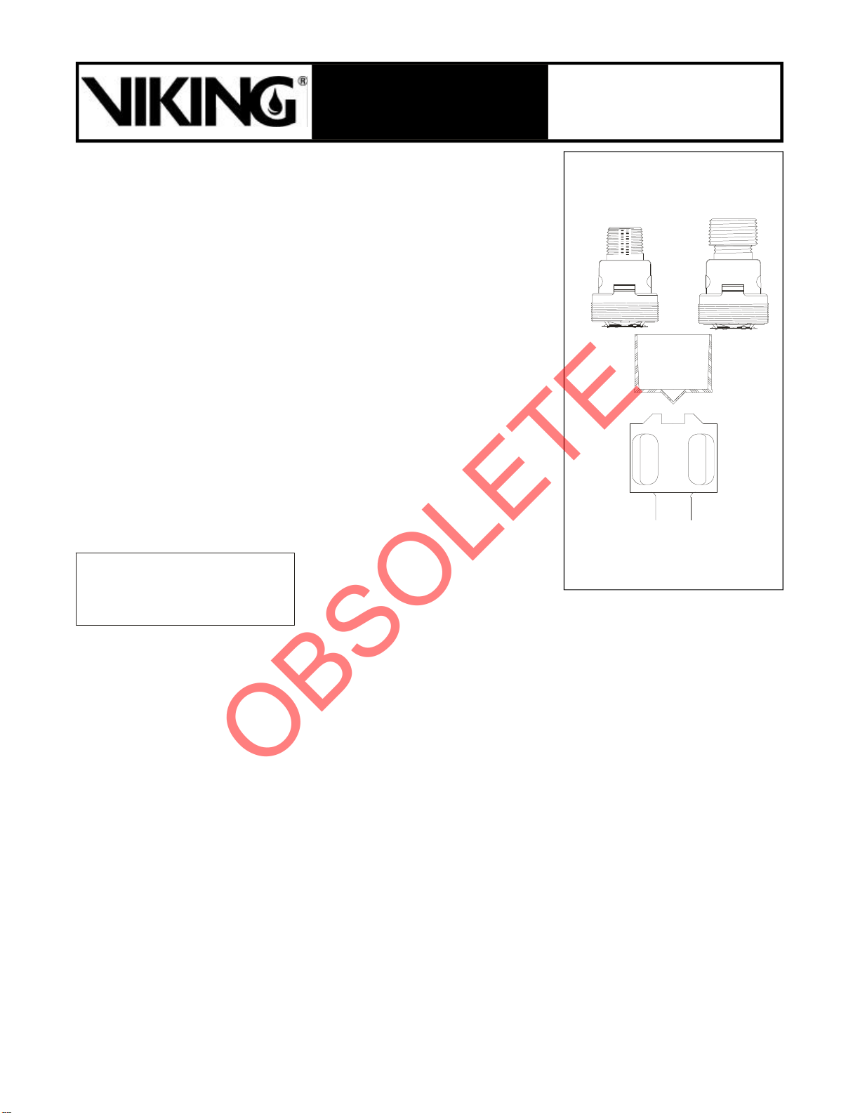
Sprinkler 58 b
1/2" NPT Sprinklers:
P/N 08498 (std. orifice)
P/N 10485 (large orifice)
3/4" NPT
Sprinkler:
P/N 10680
(large orifice)
Protective
Shell
May 25, 2000
TECHNICAL DATA
HORIZON®MIRAGE®
QUICK RESPONSE
EXTENDED COVERAGE
CONCEALED SPRINKLERS
Figure 1
Concealed Sprinkler Wrench** Part No.
08336W/B (shown) or Part No. 10366W/B
**A 1/2" ratchet is required (not available through Viking).


