BigTop 92721 User manual

ASSEMBLY INSTRUCTIONS
PORTABLE CANVAS
GARAGE
Logo Goes Here
92721
3491 Mission Oaks Blvd., Camarillo, CA 93011
Visit our Web site at http://www.harborfreight.com
®
Copyright©2005 by Harbor Freight Tools®. All rights reserved. No portion of this manual or any
artwork contained herein may be reproduced in any shape or form without the express written
consent of Harbor Freight Tools.
For technical questions and replacement parts, please call 1-800-444-3353.
TO PREVENT SERIOUS INJURY,
READ AND UNDERSTAND ALL WARNINGS
AND INSTRUCTIONS BEFORE USE.
Due to continuing improvements, actual product may differ slightly from the product described herein.

SKU 92721 For technical questions please call 1-800-444-3353. Page 2
Unpacking
When unpacking the Canvas Car Garage, check to make sure parts in the parts list and
diagram at the end of this manual are included. If any parts are missing or broken, please call
HARBOR FREIGHT TOOLS at 1-800-444-3353.
Contents
Unpacking ....................................................................................................... 2
Specifications ................................................................................................. 3
Safety Warnings and Precautions................................................................. 3
Assembly - Frame Assembly......................................................................... 5
End Frame Arches ........................................................................................................... 5
Middle Frame Arches ...................................................................................................... 5
Standing Frame Upright .................................................................................................. 6
Stabilizing at Floor Level ................................................................................................ 7
Assembly - Canvas Installation..................................................................... 8
Stretching the Canvas Over the Frame .......................................................................... 8
Door Installation .............................................................................................................. 9
Assembly Diagram ....................................................................................... 10
Maintenance.................................................................................................. 10
Parts List ....................................................................................................... 11
Parts Illustration ........................................................................................... 11

SKU 92721 For technical questions please call 1-800-444-3353. Page 3
Safety Warnings and Precautions
WARNING: When using product, basic safety precautions should always be
followed to reduce the risk of personal injury and damage to equipment.
Read all instructions before using this product!
1. Keep work area clean. Cluttered areas invite injuries. Canvas Car Garage can be hosed
off to clean.
2. Observe work area conditions. Keep work area well lit. Avoid sharp edges when
assembling. Assemble on a flat and leveled area.
3. Check for damaged parts. Before using any product, any part that appears damaged
should be carefully checked to determine that it will perform its intended function. Check
for any broken or damaged parts and any other conditions that may affect its operation.
Replace or repair damaged or worn parts immediately. Check that any of the components
are not cracked or have splits that could affect the function and performance.
4. Replacement parts and accessories. When servicing, use only identical replacement
parts. Use of any other parts will void the warranty.
5. Always check hardware and assembled parts after assembling. All connections should
be tight and hardware tightened.
6. Keep children away. Children must never be allowed in the work area. Do not let them
play in or near the Garage.
7. Dress Properly. Protective non skid footwear is recommended when setting up the Canvas
Garage. Wear restrictive hair covering to contain long hair.
SAVE THIS MANUAL
You will need the manual for the safety warnings and precautions, assembly
instructions, operating and maintenance procedures, parts list and diagram. Keep your
invoice with this manual. Write the invoice number on the inside of the front cover.
Keep the manual and invoice in a safe and dry place for future reference.
DESCRIPTION
ITEM
Specifications
The Portable Canvas Car Garage is made of breathable canvas that prevents condensation
inside the garage. UV treated for long life. Heavy duty steel frame with rope threaded
through grommets.
Material Thickness
Outside Dimensions
Anchors
Steel Tubing, Wall Tubing, 1.5” Dia.-
Support Braces, Frame, 1.13” Dia.-Canvas Cover, 0.04” Thick
16.8’ L x 9.8’ W x 9’ H
Zinc Plated Steel Spikes

SKU 92721 For technical questions please call 1-800-444-3353. Page 4
8. Always wear ANSI approved safety goggles and hardhat while setting up, taking
down, or maintaining this product.
9. Do not overreach. Keep proper footing and balance at all times.
10. Do not try moving assembled Canvas Car Garage. Do not lift the Canvas Car Garage.
This cumbersome product may require as many as 6 people to safely assemble it.
11. Weight on top of the garage can result in the Garage tipping or the canvas tearing,
resulting in property damage or SEVERE PERSONAL INJURY. Do not place anything
on top of the Canvas Car Garage. NEVER allow snow, plant material, or other debris to
accumulate on top of the Garage.
12. Avoid harsh conditions
.
The Canvas Car Garage could topple in strong winds causing
damage to property and personal property. Disassemble if weather conditions become
severe and could damage the Canvas Car Garage.Harbor Freight Tools is not responsible
for damage due to weather conditions and will not be held responsible for a Canvas Car
Garage exposed to and/or damaged by conditions such as high winds, heavy rain, snow
or ice under any condition.
13. You will need to remove the cover when you know that severe weather conditions are
approaching. And if covered, frequently check the anchoring system to ensure stability of
the Canvas Car Garage. Proper anchoring is your responsibility.
14. NEVER use any combustion-powered appliances (such as gasoline,
diesel, propane, or natural gas powered) or burn anything (such as a fire,
candle, or smoldering coals) within or near this tent. Carbon monoxide
will accumulate within this tent if such appliances are used, and this gas
is DEADLY in an environment lacking proper ventilation.
In addition, heat sources can ignite the canvas cover of this Garage. Make
certain that any burning heat sources or combustion-powered appliances
are kept at least 15’away from the Garage. Any non-combustion heaters
must be kept at least 3’ from the side of the Garage and must not be
pointed at the walls of the Garage. The canvas cover and doors of this
Garage are NOT fire retardant.
15. This Garage is not intended to contain animals.
16. Check and carefully adhere to all federal, state, and local ordinances and regulations
regarding any chemicals or flammable materials that you wish to store within this
Garage.
17. WARNING: The brass components of this product contain lead, a chemical known to the
State of California to cause birth defects (or other reproductive harm).
(California Health & Safety code § 25249.5,
et seq.
)
Warning: The warnings, cautions, and instructions discussed in this instruction
manual cannot cover all possible conditions and situations that may occur. It must be
understood by the operator that common sense and caution are factors which cannot
be built into this product, but must be supplied by the operator.

SKU 92721 For technical questions please call 1-800-444-3353. Page 5
Assembly - Frame Assembly
End Frame Arches
•Assemble end pieces and frame on the ground.
•Do not attempt to stand the frame upright until all parts of the arches are assembled.
•At least 6 people total are required to assemble this item safely.
1. Assemble the arch on the end of the Garage frame with two End Slope Tubes (6a)* and
the Three Way Curved Joint (9). Press to fit with a Rubber Mallet (not included). Connect
the Door Tube (7) as shown in the
Figure A and Drawing on Page 10.
You may need to
tap or hold the Door Tube in place while it is secured. Secure with Cap Nut & Bolts (12a).
*The End SlopeTubes (6a) have a hole in the middle to attach the DoorTube (7). Center SlopeTubes
(6a) have no such hole.
2. Assemble another Three Way Joint (9) to the end of the arch and attach a Wall Tube (3) to
it. Connect a second Wall Tube (3) under the first. Parts are pressure fitted together. (Use
a rubber mallet to tap together). Repeat for the other side of the arch.
See Figure B.
3. Assemble a Two Way Joint (11) to the bottom of each Wall Tube (3). The Two Way Joint
must be at a right angle to the assembled arch.
See Figure C.
4. Continue constructing the other end frame in the same manner. Set it aside.
Middle Frame Arches
1. On the ground, assemble two Center Slope Tubes (6b) to the angled tubes on a Four Way
Joint (8), forming an arch. The two free ends of the Four Way Joint (8), if assembled
properly, should be in a straight line.
2. On the other end of the Center Slope Tubes (6b), attach a Wall Tube (3) with another Four
Way Joint (8). Once again, the two free ends of the Joint must be in a straight line. Attach
another Wall Tube (3) into the bottom of the first. This will form a “horseshoe” shaped
middle frame.
3. Then attach a Three Way Bottom Joint (10) to the bottom of each WallTube (3). The Three
Way Bottom Joint must be at a right angle to the assembled arch. The Joint-Tube assembly
should look like a T after being connected.
Note: Tap all joints until they are flush.
See Figure B.
4. Set this assembly aside and continue constructing middle frames. There are a total of
three.
Figure A
Cap Nut & Bolt
(12a)
Door Tube (7)
Figure B
Slide Until
Flush

SKU 92721 For technical questions please call 1-800-444-3353. Page 6
Standing Frame Upright
1. Start with an assembled End Frame Arch of the Car Garage. Insert a Foundation Tube (2)
into the end of the Two Way Joint (11), being sure the small holes on the side of the
Foundation Tube are facing out from the center of the garage. See Figure C.
2. Using at least five assistants, erect the back End Arch and have two assistants hold it
erect. Using three assistants, erect one of the Middle Frame Arches next to the end of the
Foundation Tubes (2). Connect the Foundation Tubes (2) to the Three Way Bottom Joints
on both sides of the Middle Frame Arch. Have two assistants hold the Middle Frame Arch
up. Have an assistant support a sturdy ladder (not included) while Running Tubes (5) are
installed connecting the tops of the Arches from the Three Way Curved Joints (9) to the
Four Way Joints (8). Tap all connections securely together with a rubber mallet. Continue
to have all four assistants hold the assembly for now, it is not stable yet.
3. Locate one of the Wall Running Tubes (4) with a curved end. Attach the curved end to the
hole in the center of the Wall Tube (3) on the End Frame Arch. Secure with a short Cap
Nut and Bolt (12a), with the head of the Bolt facing toward the outside. See Figure D.
Secure the opposite end to the same place on the Middle Arch, using a long Cap Nut and
Bolt (12b). Repeat this step for the other side of the arch.
4. When this portion of the frame is assembled, move the frame to your desired location.
Choose an area that is level and free of stones or stumps. The first two arches should be
somewhat more stable now, so it can possibly be supported by only two assistants after
moving.
5. Attach the next Middle Arch by following Steps 1 & 2 on the previous page (all Three Way
Curved Joints (9) will be Four Way Joints (8), and all Two Way Joints (11) will be Three
Way Bottom Joints). Locate one of the Wall Running Tubes (4) with flat ends. Carefully
remove one of the long Cap Nut and Bolts (12b) and attach one end of the new Running
Tube (4) to it in addition to the first Running Tube. Secure the opposite end of the Tube to
the same place on the next Arch, using a long Cap Nut and Bolt (12b). Repeat this step
for the other side of the arch.
6. Repeat all procedures in step 5 again for the last Middle Arch.
Two Way
Joint (11)
Wall Tube (3)
End Frame
Foundation
Tube (2)
Figure C Figure D
Outside of
Frame
Curved End
Wall
Running
Tube (4)
Cap Nut &
Bolt (12a)
on inside of
Frame.

SKU 92721 For technical questions please call 1-800-444-3353. Page 7
7. Attach the End Arch by following Steps 1 & 2 on the previous page. Locate one of the Wall
Running Tubes (4) with a curved end. Attach the curved end to the hole in the center of
the Wall Tube (3) on the End Frame Arch. Secure with a short Cap Nut and Bolt (12a),
with the head of the Bolt facing toward the outside. Carefully remove one of the long Cap
Nut and Bolts (12b) and attach the other end of the Running Tube (4) to it in addition to the
first Running Tube. Repeat this step for the other side of the arch.
Stabilizing at Floor Level
1. Snap the rounded end of the right and left Foundation Plates (1) over the Foundation
Tubes (2). They will overlap in the center floor of the Garage.
2. Match up the holes and secure with Nut & Bolt (13). Space these Plates out for stability,
and secure into place with Spikes (14).
See Figures E & F and Drawing on Page 10.
Figure E Figure F
Rounded
End of
Foundation
Plate (1)
Spike
(14) Nut &
Bolt (13)
Foundation
Plate (1)
Foundation
Tube (2)

SKU 92721 For technical questions please call 1-800-444-3353. Page 8
Assembly - Canvas Installation
Stretching the Canvas Over the Frame
Choose a clean dry area to lay out the Canvas Garage Cover. Note: The Back of the Garage
Cover is already assembled to the roof and the sides of the Garage Cover. Use several people
to pull, tug, and position the Cover over the frame of the Garage.
1. Position the Canvas Garage Cover (16) face side up, being aware of length and height of
Garage frame in reference to the length and width of the Cover. Smooth the Cover along
the side of the frame. Fold in half lengthwise. Position the folded Cover as close to the
frame as possible. Attach a long rope (not provided) in holes on each end of the Cover.
These ropes will be used to guide and pull the Cover (16) over the top of the frame and
pulling down the sides and back.
See Figure G.
2. Use at least six people to help position the Cover (18) over the frame. It is suggested to
have a person on a ladder at each end of the frame to assist with lifting. For safety, have
someone to support the ladder so it will not topple over. Use two to four other people to
pull the ropes and shift the Cover (18) into position.
3. Snugly stretch the Front Gable Cover (18) at the peak of the roof frame.
See Figure H.
4. Slip the Hooks on the bottom of the Canvas Cover into the holes in the outer side of the
Foundation Tubes (2). This will help prevent wind from flapping the sides of the Garage.
See Figure J.
Underside
of Tarp
Outside of
Tar p
Frame
Rope
Rope
Figure G
Tar p Co ve r
(23)
Figure H
Front Gable
Cover (18)
Figure J
Hooks on
Canvas Cover Foundation
Tubes (2)

SKU 92721 For technical questions please call 1-800-444-3353. Page 9
Door Installation
1. Once the Canvas Garage Cover (16)
is snugly stretched over the frame, attach the right
and left Canvas Doors (17) with the hooks over the Door Tube (7).
See Figures K & L.
2. From the top of the Door (17), stick the rope loops through the grommets in the Canvas
Cover, capturing the side of the Door (17). Pass the loops through each other in sequence
as shown in
Figures M & N.
Repeat on other Door (17). At the bottom of the Door, tie the
Rope (15) to the corner tube on all four corners. Check periodically & tighten if needed.
Canvas
Door
Left (17a)
Canvas
Door
Right (17b)
Figure L
Door
Tube (7)
with
Hooks
Figure K
Figure N
tie off
Figure M
Rope
(15)

SKU 92721 For technical questions please call 1-800-444-3353. Page 10
Maintenance
1. Cover can be cleaned with soap & water.
2. For better and safer performance, keep all parts of this product clean and dry.
3. Periodically check to see that all hardware is in place and ropes are tight.
Assembly Diagram
5
5
5
5
7
6a
5
12a
4
3
11
10
14
2
8
12a
9
13 114
12b
6b
3

SKU 92721 For technical questions please call 1-800-444-3353. Page 11
PLEASE READ THE FOLLOWING CAREFULLY
THE MANUFACTURER AND/OR DISTRIBUTOR HAS PROVIDED THE PARTS DIAGRAM IN THIS MANUAL AS A REFERENCE
TOOL ONLY. NEITHER THE MANUFACTURER NOR DISTRIBUTOR MAKES ANY REPRESENTATION OR WARRANTY OF ANY
KIND TO THE BUYER THAT HE OR SHE IS QUALIFIED TO MAKE ANY REPAIRS TO THE PRODUCT OR THAT HE OR SHE IS
QUALIFIEDTO REPLACE ANY PARTS OFTHE PRODUCT. IN FACT,THE MANUFACTURER AND/OR DISTRIBUTOR EXPRESSLY
STATES THAT ALL REPAIRS AND PARTS REPLACEMENTS SHOULD BE UNDERTAKEN BY CERTIFIED AND LICENSED
TECHNICIANS AND NOT BY THE BUYER. THE BUYER ASSUMES ALL RISK AND LIABILITY ARISING OUT OF HIS OR HER
REPAIRSTOTHE ORIGINAL PRODUCT OR REPLACEMENT PARTSTHERETO, OR ARISING OUT OF HIS OR HER INSTALLATION
OF REPLACEMENT PARTSTHERETO.
Parts Illustration
18
17b
16
15
17a
Parts List
traPnoitpircseD.ytQtraPnoitpircseD.ytQ
1etalPnoitadnuoF611tnioJyaWowT4
2ebuTnoitadnuoF8a21”2)trohs(stloB&tuNpaC8
3ebuTll
aW02b21”4/1-2)gnol(stloB&tuNpaC6
4ebuTgninnuRllaW831tloB&tuN6
5ebuTgninnuR2141sekipS22
a6ebuTepolSdnE451epoR1
b6ebuTepolSretn
eC661revoCegaraGsavnaC1
7ebuTrooD2a71.tRrooDsavnaC1
85x"51(tnioJyaWruoF
3
/
4
5x"
3
/
4
)"9 b71.tLrooDsavnaC1
95x"51(tnioJdevruCyaWeerhT
3
/
4
)"6 81revoCelbaGtnorF1
01tnioJmottoByaWeerhT6
Table of contents
Popular Tent manuals by other brands

ShelterLogic
ShelterLogic 12'W x 8'H instructions
Skandika
Skandika Canopy Gotland 5 Setup & maintenance
weinor
weinor VertiTex II Instructions for assembly
Zempire
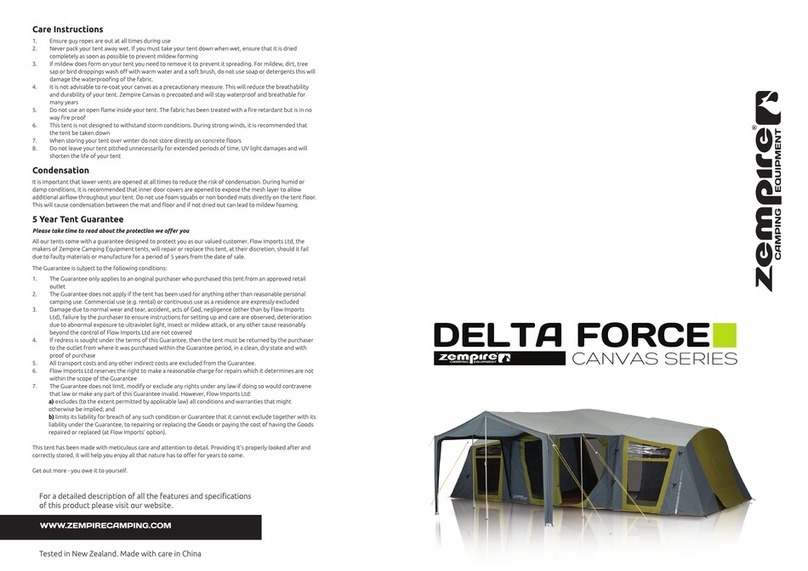
Zempire DELTA FORCE CANVAS Series instructions

Roam Adventure
Roam Adventure Vagabond user manual

skandika outdoor
skandika outdoor HAMMERFEST 6 Setup Instruction
