Bilanciai PS440-A Series Installation instructions

Italiano
English
Français
Deutsch
81320396 05/11/2018
Alimentatore PS440-A/xxx per terminali di pesatura
Istruzioni di sicurezza
Power supplier PS440-A/xxx for weighing terminals
Safety instructions
Alimentation PS440-A/xxx pour indicateurs de pesage
Consignes de sécurité
Versorgungsgerät PS440-A/xxx für Wägeterminals
Sicherheitsanweisungen


_____________________________PS440-A/xxx__
1
Table of Contents
1. Description........................................................................................................................... 3
2. Mechanical specifications ................................................................................................... 3
3. Electrical specifications ...................................................................................................... 4
4. Marking................................................................................................................................. 5
4.1 AREAS AND CATEGORIES...................................................................................... 5
5. Safety instructions for installation in hazardous areas.................................................... 6
5.1 WIRING DIAGRAM ................................................................................................ 7
5.1.1 Exe Connections .......................................................................................... 8
5.1.2 Exi Connections........................................................................................... 8
5.1.3 Conductor connections................................................................................ 8
5.2 CASING ................................................................................................................ 9
5.3 CABLE GLANDS .................................................................................................... 9
5.4 APPLICATION EXAMPLE........................................................................................ 9
6. Instructions for disposing of waste electrical or electronic equipment......................10
7. Example of Declaration of Conformity .........................................................................11

2

3
Foreword
_____________________ Note _____________________
Document relating to CESI 05 ATEX 023 certificate.
No changes are permitted without the approval of the Authorised Body
_______________________________________________
1.Description
Power supplier PS440-A/xxx accepts various voltages on the input, as indicated
in the following table:
PS440/230Vac: 230 Vac input voltage
PS440/115Vac: 115 Vac input voltage
PS440/24Vac: 24 Vac input voltage
Power supplier PS440/xxx provides the necessary voltages and interfacing
signals for operating weighing terminal D440IS, by means of intrinsic safety
circuits.
The power supplier is suitable for operation in areas where there is a risk of
explosion. It is made in compliance with directive ATEX 2014/34/UE and
according to standards EN60079-0, EN60079-7, EN60079-11, EN60079-18,
EN60079-26, EN60079-31, with the following protection modes:
GAS: Ex e mb [ia Ga], T4 Gb
DUST: Ex tb mb [ia Da] IIIC T100°C, T135°C Db
Ambient operating temperature
Tamb (-20°C ÷ +40°C) → T5/T100°C
Tamb (-20°C ÷ +55°C)→ T4/T135°C
The PS440-A/xxx comes in an IP66 protection degree polyester case with Ex-
e/Ex-t cable clamp (object of separate certification) for cable entry.
2.Mechanical specifications
Cable gland
M16x1.5
Cable diameter: 6.5 –12 mm
4
3.Electrical specifications
Mains power supply
L (line), N(neutral), T(ground)
PS440/230Vac
PS440/115Vac
PS440/24Vac
Pn=20VA
Fn=50/60Hz
Un =230Vac
Un =115Vac
Un =24Vac
Um=250V
Outputs (clean contacts)
Out1 terminals 1-2
Out2 terminals 3-4
Out3 terminals 5-6
Out4 terminals 1-2
UMAX=125Vac/dc
I MAX=200mA
Display power supply
Terminals 19(+) 16(-)
CPU Power supply
Terminals 18(+) 16(-)
Uo =12.24V
Io = 860mA
Po = 2.6W
Co 1.28uF
Lo 25µH
Input power supply
Terminals 17(+) 16(-)
Uo =17.6V
Io = 393mA
Po = 1.7W
Co 333nF
Lo 60H
Load cell power supply
Terminals 15(+) 14(-)
Uo =6.6V
Io = 231mA
Po = 381mW
Co 22F
Lo 500H
Output commands
C-Out 1 Terminals 13(+) 9(-)
C-Out 2 Terminals 12(+) 9(-)
C-Out 3 Terminals 11(+) 9(-)
C-Out 4 Terminals 10(+) 9(-)(not
connected)
Uo =6.6V
Io = 42mA
Po = 63mW
Co 40F
Lo 10mH
5
4.Marking
0722 CESI YY ATEX nnn
II 2(1) G Ex e mb [ia Ga] IIC T5, T4 Gb
II 2(1) D Ex tb mb [ia Da] IIIC T100°C, T135°C Db
Tamb (- 20°C ÷+ 40°C)T5/T100°C
Tamb (- 20°C ÷+ 55°C)T4/T135°C
0722
number of the Notified Body for ATEX surveillance (CESI)
CESI YY ATEX nnn
Number of certificate and body that issued it
II
group II (surface)
2 (1)
category of equipment
G
explosive atmosphere where gas, mist or vapour are present
Ex e mb [ia Ga]
IIC
protection method
group of gas
T5, T4
Gb
D
Ex tb mb [ia Da]
IIIC
gas temperature category
EPL GAS
explosive atmosphere with dust
protection method
conductive dust
T=100°C, 135°C
maximum surface temperature of casing
Db
EPL DUST
Operating ambient
temperature
- 20 °C ÷ + 40 °C (T5/T100°C)
- 20 °C ÷ +55 °C (T4/T135°C)
IP66
protection degree of casing
4.1 Areas and categories
Hazardous area
Categories according to
Directive 2014/34/UE
Equipment protection level
Gas, vapours or mist
Area 0
1G
Ga
Gas, vapours or mist
Area 1
1G or 2G
Ga or Gb
Gas, vapours or mist
Area 2
1G, 2G or 3G
Ga, Gb or Gc
Dust
Area 20
1D
Da
Dust
Area 21
1D or 2D
Da or Db
Dust
Area 22
1D, 2D or 3D
Da, Db or Dc

6
5. Safety instructions for installation in hazardous areas
Power supplier PS440/xxx (note 1) must be installed and serviced in compliance
with the installation and maintenance instructions for sites classified against the
risk of explosion, owing to the presence of gas and dust (example: EN 60079-
14, EN 60079-17 or other national norms/standards).
Warning: carefully read the technical specifications enclosed with both power
supplier PS440-A/xxx (note 1) and terminal D440IS.
Plate warning:
“DO NOT OPEN WHEN UNDER POWER”
Note 1:
Power supplier PS440-A/xxx is supplied for different powering voltage
ratings. The xxx suffix indicates the value and type of power input.

7
5.1 Wiring diagram
Figure 1 Block diagram of the connections
The terminal part of D440IS is not described in these Safety Notes. Please refer
to the related documentation for more details.

8
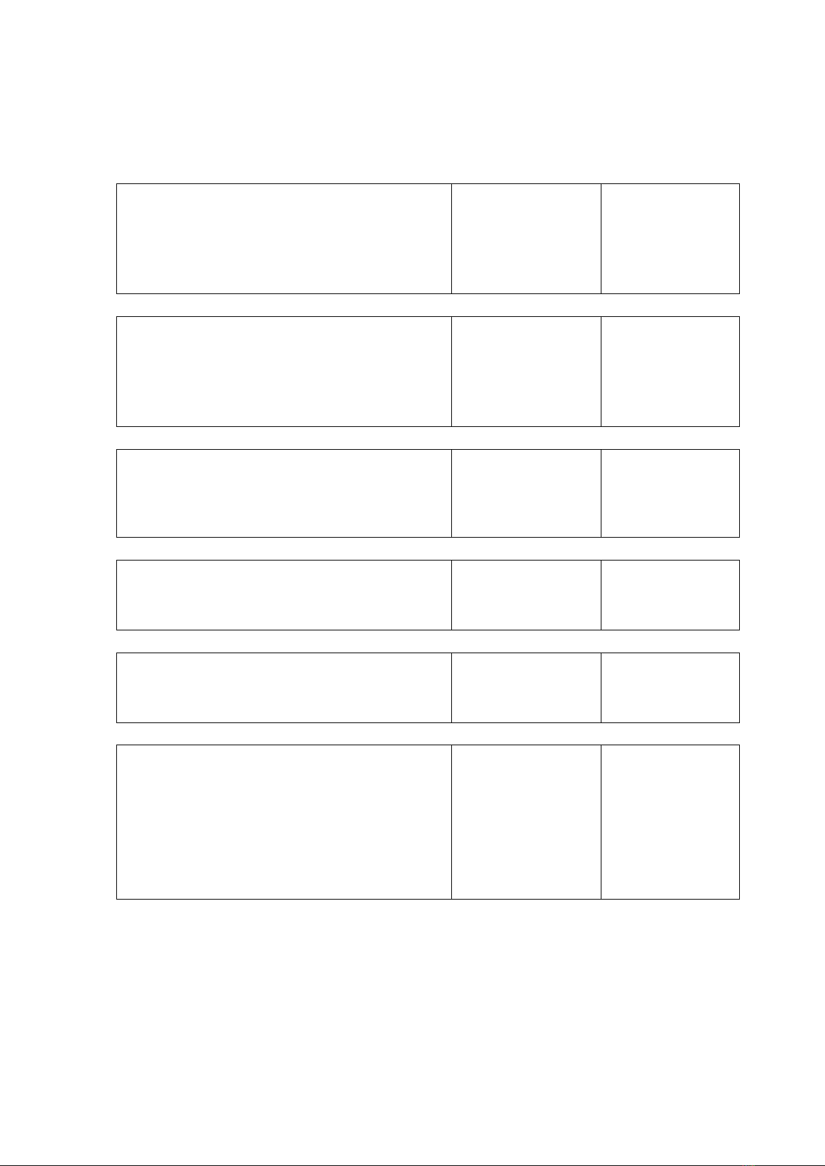
5.1.1 Exe Connections
Terminal N°
Signal
Description
L
Line
Power supply: line
T
Ground
Safety ground connection
N
Neutral
Power supply: neutral
5.1.2 Exi Connections
Terminal N°
Signal
Description
1
OUT1
Output 1
2
COM1
Common 1
3
OUT2
Output 2
4
COM2
Common 2
5
OUT3
Output 3
6
COM3
Common 3
9
GND_RELAY
Common relay command
11
C-Out3
Output 3 command
12
C-Out2
Output 2 command
13
C-Out1
Output 1 command
14
EXC-_EX
exi - load cell power supply
15
EXC+_EX
exi + load cell power supply
16
DGND
Digital ground
17
+14INPUT_EX
exi power supply of the inputs and of the
board 4-20 mA analog current output
18
+6V_EX
exi power supply for CPU
19
+6VDISP_EX
exi power supply for display
5.1.3 Conductor connections
Prepare conductors with insulated pins for connection to the terminals.
Keep the exi conductors separate from the non-exi ones.
9
5.2 Casing
The user must clean the casing regularly, to prevent a layer of dust from
forming.
5.3 Cable glands
Insert the conductors into the cable glands and then tighten these latter.
Unused cable glands must be closed with the supplied plugs.
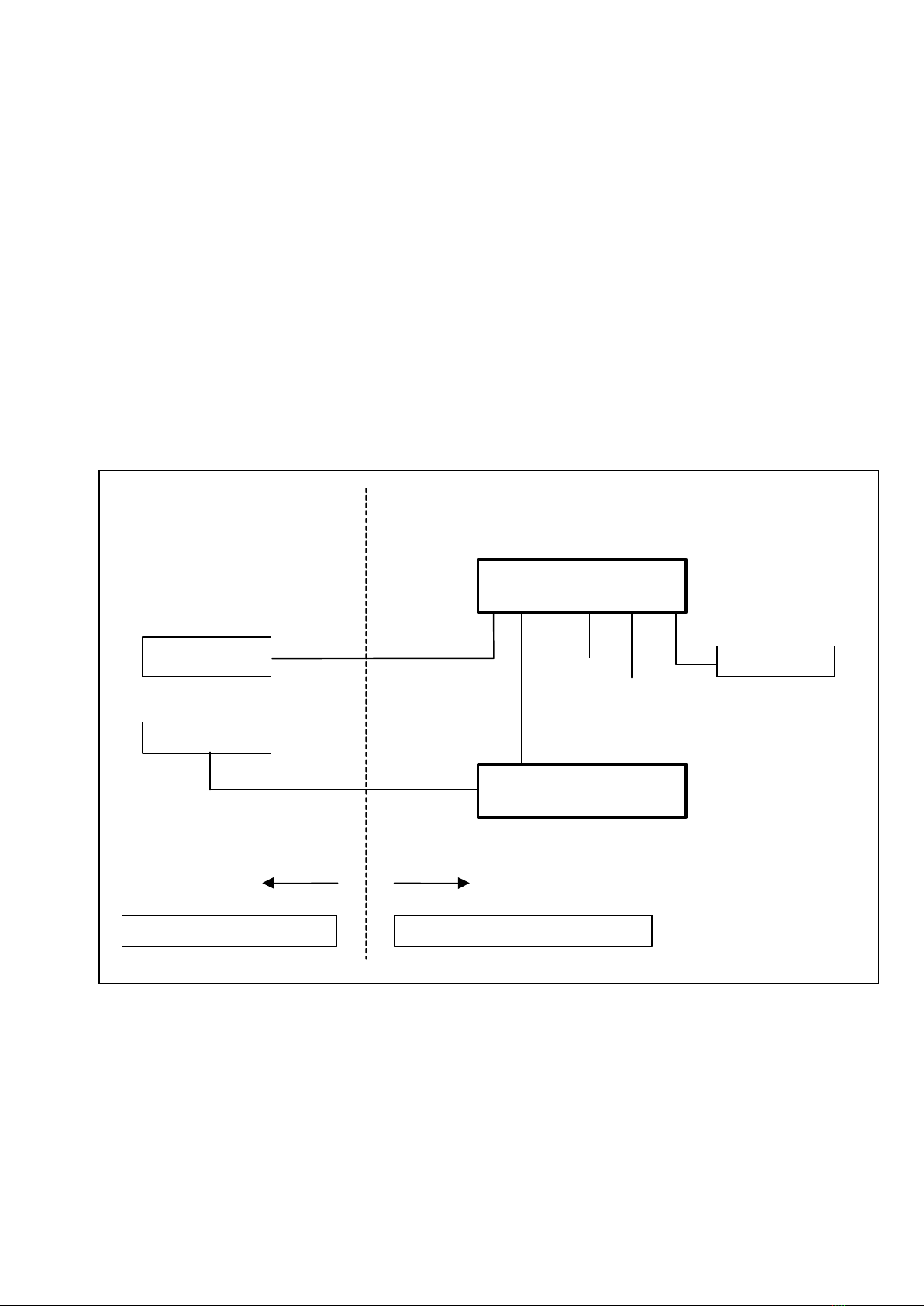
5.4 Application example
Figure 2 Application example
Note (*): optic fiber and analog output can be installed as alternatives
230
Vac
SAFE AREA
HAZARDOUS AREA
CELL 1…..4
L+N+T
D440
IS
PS440/230V
ac
PC
Optic fiber (*)
Input
Output
4-20mA (*)

10
6.Instructions for disposing of waste electrical or
electronic equipment
This symbol on the weighing instrument you have purchased
means that:
this electric or electronic appliance cannot be disposed of as
solid municipal waste;
it must be collected separately;
it can be returned to the dealer when a new one is purchased;
improper use or disposal of this appliance may pollute the environment or
damage the health of human beings;
failure to comply with the aforementioned instructions is punished by law.
In particular:
the external casing and the mechanical components are made of plastic
and/or metal materials;
the casing contains printed circuits with electronic components;
the electrical connections are made with insulated copper conductors;
WARNING
Dispose of this appliance by means of separate collection or take it back
to the dealer or to a differentiated collection centre.

11
7.Example of Declaration of Conformity EU
We
SOCIETÀ COOPERATIVA BILANCIAI A.R.L.
Via S. Ferrari, 16
41011 Campogalliano - MODENA
Hereby declare under our responsibility, that products:
PS440-A/230Vac: power supplier with 230 Vac input voltage, lot/SN: ....
PS440-A/115Vac: power supplier with 115 Vac input voltage, lot/SN:......
PS440-A/24Vac: power supplier with 24 Vac input voltage, lot/SN:..........
lot/SN: See SN on the front page
described in this declaration conform to the following directives:
- Directive 2014/34/UE (ATEX)
- Directive 2014/30/UE ( EMC)
- Directive 2014/35/UE (LVD)
- Directive 2014/31/UE (NAWI)
Conformity is demonstrated by compliance with the following standards:
EN 61000-6-3 :2007
EN 61000-6-4 :2007
EN 60079-0 : 2012 EN 60079-7 : 2015
EN 60079-11 : 2012 EN 60079-18 : 2015
EN 60079-26 : 2007 EN 60079-31 : 2014
EN 45501 :2015
Mark / Protection modes:
II 2(1) G Ex e mb [ia Ga] IIC T5, T4 Gb
II 2(1) D Ex tb mb [ia Da] IIIC T100°C, T135°C Db
Tamb (- 20°C ÷ + 40°C) T5/100°C
Tamb (- 20°C ÷ + 55°C) T4/135°C
CE type certificate N°: CESI 05 ATEX 023
ATEX/Q notified body for surveillance: CESI 0722
Campogalliano, 05.11.2018 Signed for and on behalf of:
12
SOC. COOP. BILANCIAI CAMPOGALLIANO A.R.L.
41011 Campogalliano (MO) Via Ferrari, 16
tel. +39 (0) 59 893611 –fax +39 (0) 59 527079
home page: http://www.coopbilanciai.it
E-mail: cb@coopbilanciai.it
servizio post-vendita after sales service service apres-vente
Kundendienstservice servicio post-venta serviço pós-venda
tel. +39 (0) 59 893612 –fax +39 (0) 59 527294
______________________________________________________________________
This manual suits for next models
1
Table of contents


