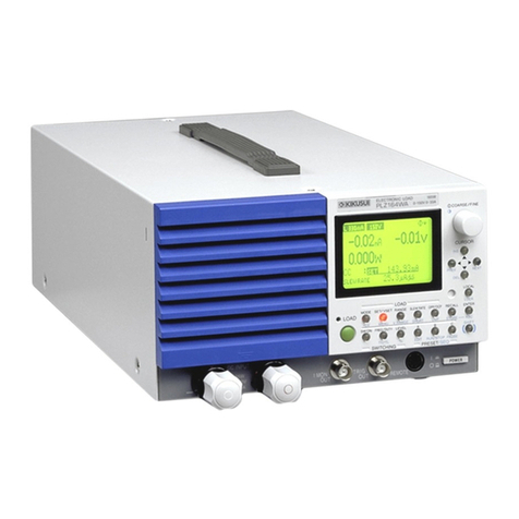
Kikusui PIA4800 Series User manual
Other Kikusui Power Supply manuals

Kikusui
Kikusui PCR-L Series User manual

Kikusui
Kikusui PWR401L User manual

Kikusui
Kikusui OT01-PCR4000LA/2 User manual
Kikusui
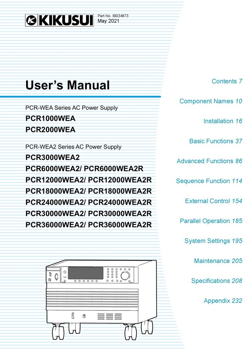
Kikusui PCR1000WEA User manual
Kikusui
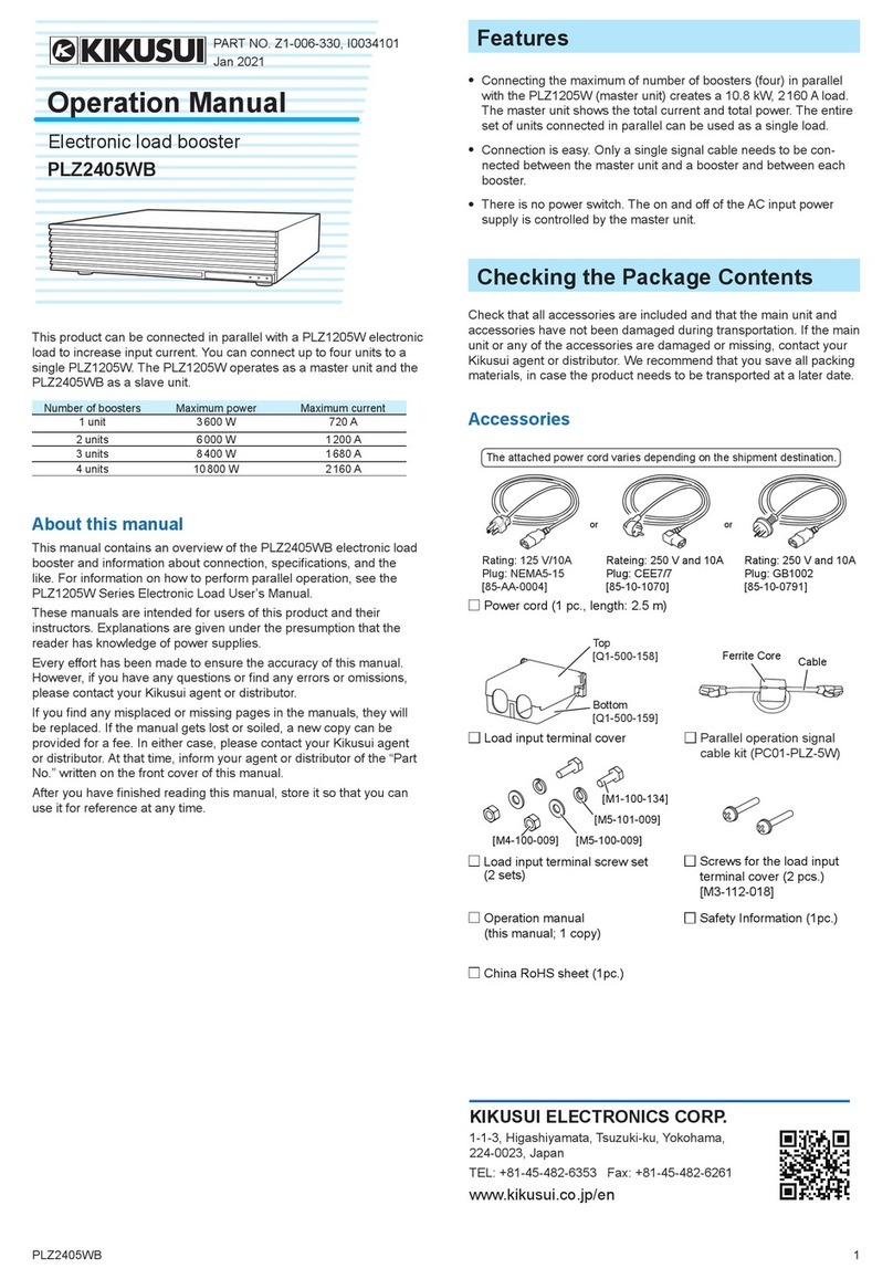
Kikusui PLZ2405WB User manual
Kikusui
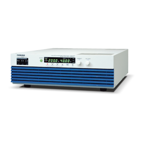
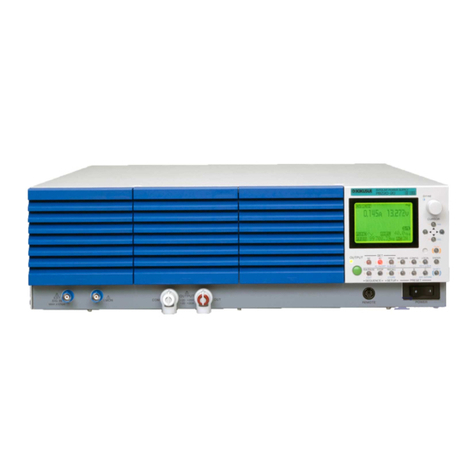
Kikusui PAT20-200T User manual
Kikusui
Kikusui PBZ Series User manual
Kikusui
Kikusui PVS 7.5-300 User manual

Kikusui
Kikusui PAB 18-1A User manual

Kikusui
Kikusui PAN16-10 User manual

Kikusui
Kikusui PAS 10-35 User manual
Kikusui
Kikusui PCR-M Series Use and care manual
Kikusui
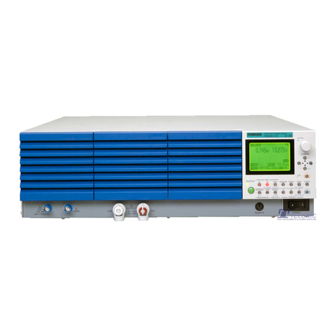
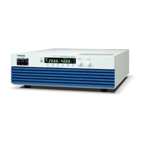
Kikusui PBZ20-20 User manual
Kikusui
Kikusui PAT-T Series User manual

Kikusui
Kikusui PCR-M Series User manual

Kikusui
Kikusui KDS6-0.2TR User manual
Kikusui
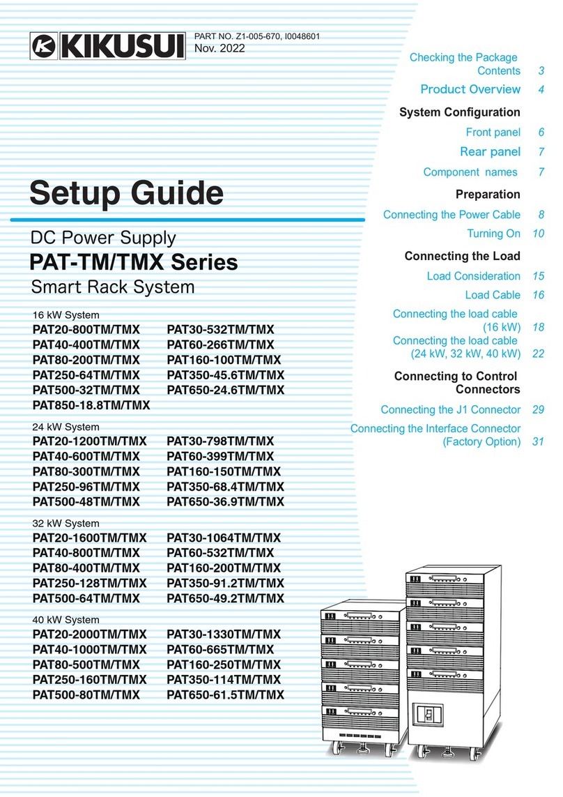
Kikusui PAT-TM Series User manual

Kikusui
Kikusui PXB Series User manual

Kikusui
Kikusui PMX32-3TR User manual
Kikusui
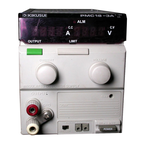
Kikusui PMC 18-1A User manual
Popular Power Supply manuals by other brands

Videx
Videx 520MR Installation instruction

Poppstar
Poppstar 1008821 Instructions for use

TDK-Lambda
TDK-Lambda LZS-A1000-3 Installation, operation and maintenance manual

TDK-Lambda
TDK-Lambda 500A instruction manual

Calira
Calira EVS 17/07-DS/IU operating instructions

Monacor
Monacor PS-12CCD instruction manual
