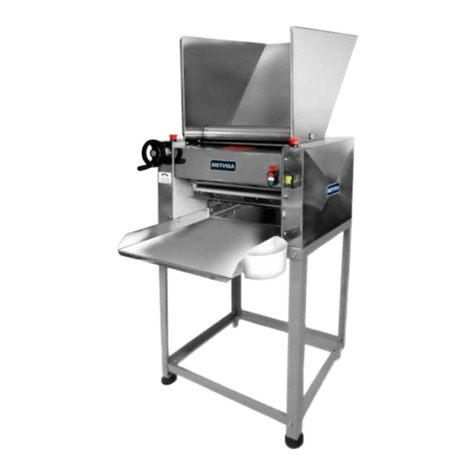
BIMG METVISA CLMM.390 User manual

1

2
INDEX
1.
Safety Information................................................................................................. 3
1.1
General warnings................................................................................................................ 3
2.
Technical Characteristics .................................................................................... 4
2.1
Main Components .............................................................................................................. 4
2.2
Technical Data.................................................................................................................... 5
3.
Installation............................................................................................................. 5
3.1
Arrangement of the Machine ............................................................................................ 5
4.
Machine Use ......................................................................................................... 7
4.1
Utility................................................................................................................................... 7
4.2
Commands.......................................................................................................................... 7
4.3
Operating Procedures......................................................................................................... 8
5.
Cleaning and Maintenance................................................................................. 10
5.1
Cleaning Procedures and Products Used ........................................................................ 10
8.
Annexes .............................................................................................................. 12
Electrical Schematic 60 Hz - Voltage 110 V or 220 V ...................................................... 12
Electrical Schematic 50 Hz - Voltage 220 V ..................................................................... 13
Exploded view drawing..................................................................................................... 14
List of Replacement Parts................................................................................................. 16
ATTENTION!
The characteristics, pictures and figures presented in this manual should be considered for
information. IMG BRASIL reserves the right to make such modifications as may be deemed
necessary without prior notice.

3
1. Safety Information
1.1 General Warnings
• Cautions / precautions must be observed when installing, using, maintaining and discontinuing use
of this equipment;
• Before carrying out any operation (assembly, use (use), maintenance and reuse after prolonged use
of the equipment), read the manual carefully;
• The machine must be used by trained personnel familiar with the use and safety regulations
described in this manual;
This appliance is not intended for use by persons (including children) with reduced physical, sensory
or mental capacities, or people with lack of experience and knowledge, unless they have received
instructions regarding the use of the appliance or are under the supervision of a person responsible
for their safety.
• It is recommended that children be supervised to ensure that they are not playing with the
equipment;
• In case of rotation of the personnel that will work with the equipment, the new operator must be
educated about the standards and the operation of the same one;
• The operator must use the Adequate PPE (equipment for individual safety). As for example: use
touches the hair avoiding that they lock in the moving parts of the machine;
• The operator must always be aware of situations that can cause a risk of accidents and avoid them.
For example: avoid working with sleeves of loose uniforms, where they can lock in moving parts,
causing accidents;
• After reading and clarifying all doubts, this manual should be carefully stored in an easily accessible
location, known to all persons who will operate the machine and make it available to those who will
carry out maintenance for any inquiries. Whenever any questions arise, be sure to check the manual.
Do not operate the machine in any way with doubts;
• In the installation, it is essential to make this manual available to the professionals who will do the
same;
• Never place your hands on rolling cylinders, or on or near moving parts;
• Before starting any cleaning and maintenance, it is essential to disconnect the equipment from the
mains;
• Periodically check the condition of the cables and electrical parts;
• Do not leave the machine switched on unattended.
ATTENTION!
Do not perform repairs on your own. Refer servicing to qualified service personnel. Only use
original parts in your machine.

4
2. Technical Features
2.1 Main Components
For the equipment described in this manual, safety in use, cleaning, maintenance and
maximum hygiene are guaranteed by the design and special project for all parts and also by using
stainless steel and other materials suitable for contact with food.
The machine was built with the following features:
• Front guard, side guards, back cover, roller support, channel, low table and slider (graduated ruler),
made of stainless steel, which has superior corrosion resistance to other steels. It is a material
resistant to the attack of several corrosive agents;
• The plastic scraper made of PE (polyethylene) plastic and the PVC plastic mixture roller are both
non-toxic, odorless, impact and corrosion resistant materials;
• The upper and lower roller cylinders are made of stainless steel, which withstands the attack of
several corrosive agents, such as most organic acids, organic substances in general, alkalis, oxysalts
etc.;
Note: Stainless steel is attacked by sulfuric acid, and also cannot withstand hydrochloric acid,
dilute sulfuric acid, chlorides and halides in general.
Below are the main components of the machine:
Note: For the exploded view
drawing with spare parts list, see
the annexes.

5
2.2 Technical Data
Model
Nominal Operational
Measurements*
Width x Height x Depth
(mm)
Net
weight
(approx.)
(kg)
Voltage
(V)
Rated
current
(A)
Capacity
(kg of mass)
CLMM390110M604
660x540x720
63.0
110
12.0
4
CLMM390220M501
660x540x720
63.0
220
5.8
4
CLMM390220M502
660x540x720
63.0
220
5.8
4
CLMM390220M504
660x540x720
63.0
220
5.8
4
CLMM390220M604
660x540x720
63.0
220
6.8
4
* Height and depth measurements considered with the mixing roll.
Noise level: 74 db.
ATTENTION!
Features like: model, serial number and voltage of the equipment are provided on the label
(figure below). Before installation, check that the power supply voltage of the appliance
corresponds to that of the mains.
3. Installation
3.1 Machine Layout
The connection to the mains and the arrangement for operation must be carried out by a
qualified professional. Check that the machine voltage matches the mains voltage.

6
It is essential to make this manual available to the professionals who carry out the
installation.
For ease of transportation, the machine is packed with the low table, mixing roller holder and
wheel handle crank disassembled.
To mount the crank, it is necessary to thread it onto the wheel handle. The fastening of the
mixing roller and the low table should be done using the washers and screws that come with the
machine.
Follow the guidelines below to assemble and secure the low table:
After fixing the table, place the machine on a stand with an average height of 80 cm in a
sufficiently wide, level, dry and stable area, away from heat sources, water faucets and areas with
high circulation of people. Install the machine leaving a free area on the front and a minimum distance
of 50 cm on the sides and back so there is enough space for inspection, maintenance, cleaning and
use.

7
ATTENTION!
The installation and the place where the machine will be disposed must comply with the
norms of risk prevention and safety at work (regulatory norm in force in your country).
The manufacturer shall not be liable for any direct or indirect damages caused by non-
compliance with these standards and other instructions presented in this manual.
4. Use of the Machine
4.1 Utility
This machine is exclusively intended for rolling various food mixtures.
ATTENTION!
The machine only rolls fine mixtures (e.g. lasagna, pasties etc.). It is not suitable for kneading
(e.g. bread dough).
4.2 Commands
The machine is composed of the on/off button, the wheel handle and the cursor.
The power button, wheel handle and cursor are positioned on the front of the machine.

8
View the description of each command below:
• On/Off Button - Used to turn the machine on and off. In position "1" it turns the device on, and turns
it off in position "0".
• Wheel Handle - This has the function of regulating the distance between the rolling cylinders. It
should be rotated clockwise to close the cylinders and counterclockwise to open them. As the handle
is rotated, the cursor will move.
• Cursor - Operated using the wheel handle. It indicates the thickness of the mixture by means of a
marking on the cursor and the scale label.
4.3 Operating Procedures
Before operating the machine, clean it well, especially of the components that will come into
contact with the mixture. Carry out cleaning with the machine disconnected from the mains. Follow
the cleaning instructions in item 5 of this manual (below).
After this initial care, confirm that the supply voltage of the mains is the same as that of the
machine and check the direction of rotation of the motor. To do so, start the machine and follow the
rotation of the lower roller cylinder, which must be rotating clockwise according to the image below.

9
ATTENTION!
If it is rotating counterclockwise, check that the electrical connection is reversed with
respect to the electrical wiring diagram (item 9 - Annexes) or contact your nearest
authorized service center.
• Operation: The machine can only be operated after verifying its ideal positioning, if the low table is
correctly fitted and fixed by the screws, according to the instructions in item 3.1 (Arrangement of the
Machine).
After checking these items, follow the operating procedure of the machine:
• Connect the power cord to the mains;
• Open the cylinders at the maximum (cursor at position 20 on the scale);
• Turn the power switch to "1" (on) and leave the machine on for a few seconds;
• Position it in front of the low table and throw some flour into the chute (enough for the mixture to
slide through);
• Place the mixture in the chute so that it is conducted by the cylinders, ensuring that your hands do
not pass the front guard on the machine;
• Remove the mixture from the low table;
• Close the cylinders gradually until the ideal thickness is obtained;
•When the mixture is longer than the low table surface, wrap the mixture on one of the rollers and fit it
onto the support. Guide the end of the mixture into the duct and unwind it until it is conducted by the
cylinders. Using the second roller, roll up the mixture again;
• After the process is completed, switch off the machine by switching the power button to the "0" (off)
position.
ATTENTION!
If the dough is stuck in the chute or one of the guards, turn the machine off by switching the
power button to the "0" (off) position, unplug the mains cord, and remove the mixture safely.
Throw more flour into the chute and perform the rolling operation again as instructed above.

10
ATTENTION!
Do not add all of the mixture at once with the cylinders closed. If you still notice that the
machine cannot process the mixture or that it is not processing, decrease the amount.
Only increase the mixture gradually so as not to impair the motor speed and performance,
as well as the working life of the machine.
Failure to comply with these guidelines will be considered an unsafe act and abusive use of
the machine.
In the case of any irregularities please contact your nearest authorized service center.
ATTENTION!
Never place your hands, fingers or objects (such as spoons and knives) directly into the
cylinders with the machine turned on as this may cause an accident.
5. Cleaning and Maintenance
5.1 Cleaning Procedures and Products Used
Your machine was built with first-line materials, so use it properly and you will obtain great
satisfaction. Always keep your machine clean and well-cared for, which will make it much more
durable.
Daily cleaning of the machine must be carried out for good operation and durability.
ATTENTION!
Before performing maintenance or cleaning, make sure that the appliance is switched off
and that the plug is disconnected from the mains.
ATTENTION!
Do not use water jet to clean the machine.
IMPORTANT
This machine is not intended to be immersed in water for cleaning.
Follow the instructions below to find out which parts can be immersed and the special care
to be taken with the other parts.

11
The removable part (mixing roller) must be removed from the machine and washed with water
and neutral soap. The remainder of the machine should be cleaned as many times as possible to
prevent the residue of the mixture from drying out and sticking to the parts. For cleaning, dilute soap
or mild detergent in warm water and apply with a damp, soft cloth on the cylinders and the outside of
the machine. With a cloth moistened with water, rinse and then wipe the parts with a dry cloth. Clean
the corners well, eliminating residue from the flour and mixture.
Never use abrasive products or sponges for cleaning as they may scratch or ruin the surface
of the parts. Do not spill water on the motor and electrical parts for cleaning, as turning it on
afterwards may cause electric shock or even burn the machine.
ATTENTION!
It is extremely important that the products used in cleaning ensure maximum cleanliness
and are not toxic.

12
6. ANNEXES
Electrical Schematic
Motor 60 Hz Voltage 110 V or 220 V

13
Electrical Schematic
Motor 50 Hz Voltage 220 V
NOTE: In the above Electrical Schematic, white wires are represented by pink.

14
Exploded View Drawing

15
Exploded View Drawing

16
Replacement parts
Position
Code
Description
Qty.
1
PEP028
PVC Foot
04
2
CRC356
Welded Right Side
01
3
ARL003
Flat Washer
32
4
MSA015
Low Table
01
5
PTC160
Welded Left Side Guard
01
6
PTC161
Welded Right Side Guard
01
7
PTC155
Front Guard
01
8
TAP154
Rear Cover with Reinforcement
01
9
RBT014
Rivet
08
10
CLH013
Chute
01
11
MTE245
Electric Motor 1 HP 60 Hz 220 V
01
MTE028
Electric Motor 1 HP 50 Hz 220 V
01
MTE244
Electric Motor 1 HP 60 Hz 110 V
01
12
CJT801
Welded Motor Support
01
13
PRS012
Hexagonal Screw
01
14
POS004
Hexagonal Nut
19
15
TCE021
Print Cable 110 V
01
TCE022
Print Cable 220 V
01
16
PMT026
Motor Pulley
01
17
SPD050
Side Spacer
02
18
EIX237
Cam Articulator Shaft
01
19
CJT786
Mounted Mixture Scraper
02
20
CJT258
Pulley Mounted on the Support
01
20.1
EGG032
Gear
01
20.2
CUB006
Gear Hub
01
20.3
ROL002
Bearing
02
20.4
POL011
Movement Pulley
01
20.5
SBT042
Movement Pulley Support
01
20.6
PRR012
Screw
03
20.7
PRS007
Hexagonal Screw
01
20.8
ARL003
Flat Washer
01
21
CAM001
Cams
02
22
MAC082
Left Bushing of the Cam Shaft
01
23
MAC069
Cam Shaft Bushing
02
24
CIL024
Lower Cylinder
01
25
MAC071
Lower Cylinder Bushing
02
26
MAC070
Regulator Cylinder Bushing
02
27
EGG014
Worm Gear
01
28
EGG042
Gear
01
29
EIX146
Worm Gear Shaft
01
30
CJT260
Mounted Gear
01
30.1
PRS027
Hexagonal Screw
04
30.2
ARL002
Flat washer
04
30.3
EGG043
Gear
01
30.4
CUB005
Gear Hub
01
31
CRC365
Cursor
01
32
MNL032
Cylinder Regulator Wheel Handle
01
33
ROL010
Bearing
04
34
COR005
Belt
02
35
CRT016
Chain
01
36
CAN037
Left Corner Bushing Guide
02
37
CAN036
Right Corner Bushing Guide
02
38
CJT264
Mounted Stretcher
01
38.1
HAT023
Welded Stretch Lever
01
38.2
SPD019
Stretcher Spacer
01
38.3
CJT263
Gear
01
38.4
ARL001
Flat washer
01
38.5
PRS002
Hexagonal Screw
01
39
CJT262
Gear
02
39.1
CUB007
Gear Hub
01
39.2
EGG028
Gear
01
39.3
PRR015
Screw
04

17
Replacement Parts
Position
Code
Description
Qty.
40
CRT015
Chain
01
41
MOL009
Stretcher Spring
03
42
CHE016
On/Off button
01
43
SBT416
Plastic Roller Support
02
44
SBT360
Stainless Steel Cable Gland Support - TCE021
01
SBT361
Stainless Steel Cable Gland Support - TCE022
01
45
TCM019
Cylinder Backboard
02
46
MOL008
Tipper Locking Spring
02
47
RLO018
Mixing Roller
02
48
APE005
Retaining Ring
01
49
MOL027
Right Scraper Spring
02
50
MOL026
Left Scraper Spring
02
51
PRD062
Hexagonal Screw
04
52
PNL006
Elastic Pin
09
53
ARL004
Flat Washer
33
54
PRS010
Hexagonal Screw
08
55
PRS014
Hexagonal Screw
10
56
PRS033
Stainless Steel Hex Screw
04
57
PRS008
Hexagonal Screw
06
58
PRS007
Hexagonal Screw
10
59
CBE001
Power Cable - CLMM390220M604 / CLMM390220M504
(*A, *B)
01
CBE007
Power Cable - CLMM390220M502
(*C)
01
CBE020
Power Cable - CLMM390220M501
(*D)
01
CBE003
Power Cable - CLMM390110M604
(*E)
01
60
POS017
Hexagonal Nut
04
61
ARL009
Flat Washer
04
62
PRT005
Allen Screw w/Head
05
63
PRR005
Mac. Screw Round
02
64
PRN001
Allen Screw S/C
09
65
PRN003
Allen Screw S/C
06
66
POS005
Hexagonal Nut
08
67
PRA014
Locking Hex. Screw
30
68
APE006
Retaining Ring
04
69
CRC699
Welded Left Side
01
70
CIL023
Upper Cylinder
01
71
BCH046
Rectangular Cap
01
72
PRS018
Hexagonal Screw
06
73
CBE033
Cable Splicing
04
74
CBE092
Ground Cable Splicing
01
73
TCE004
Terminal FIT
04
74
TCE013
Female Terminal
01
75
TCE033
Threaded Connector
05

18
Notes

19
Table of contents
Other BIMG Commercial Food Equipment manuals
Popular Commercial Food Equipment manuals by other brands

Diamond
Diamond AL1TB/H2-R2 Installation, Operating and Maintenance Instruction

Salva
Salva IVERPAN FC-18 User instructions

Allure
Allure Melanger JR6t Operator's manual

saro
saro FKT 935 operating instructions

Hussmann
Hussmann Rear Roll-in Dairy Installation & operation manual

Cornelius
Cornelius IDC PRO 255 Service manual

Moduline
Moduline HSH E Series Service manual

MINERVA OMEGA
MINERVA OMEGA DERBY 270 operating instructions

Diamond
Diamond OPTIMA 700 Installation, use and maintenance instructions

Diamond
Diamond G9/PLCA4 operating instructions

Cuppone
Cuppone BERNINI BRN 280 Installation

Arneg
Arneg Atlanta Direction for Installation and Use