BIMG Metvisa DG.10 User manual

1

2
INDEX
1.
Safety Information ................................................................................................ 3
1.1
General Instructions ........................................................................................................... 3
2.
Technical Specifications ..................................................................................... 4
2.1
Main Components ............................................................................................................. 4
2.2
Technical Data ................................................................................................................... 5
3.
Installation ............................................................................................................ 5
3.1
Device Layout .................................................................................................................. 5
3.2
Electrical Connection ........................................................................................................ 6
3.3
Security Measures and User Instructions........................................................................... 7
4.
Device’s Use ......................................................................................................... 8
4.1
Utility .................................................................................................................................. 8
4.2
Commands ......................................................................................................................... 8
4.3
Operating Procedures......................................................................................................... 9
5.
Cleaning and Maintenance ................................................................................ 12
5.1
Procedures for Cleaning and Products to be used .......................................................... 12
6.
Annex .................................................................................................................. 14
Wiring Diagram –Voltage ……......................................................................................... 14
Exploded Drawing ........................................................................................................... 15
Spare Parts List ............................................................................................................... 16
WARNING!
Features, photos and figures presented in this manual should be considered for information
purposes. BIMG BRASIL reserves the right to make modifications as may be necessary without
prior notice.

3
1. Safety Information
1.1 General Instructions
• There are care/precautions that should be observed when assembling, use, maintenance and
discontinue using this device;
• Before performing any operation (installation, use, maintenance and reuse after prolonged
interruption in the use of the device), read the manual;
• The device must be used by people trained and knowledgeable in use and safety requirements
described in this manual;
• This device is not intended for use by persons (including children) with physical, sensory or mental
capacities reduced, or people with lack of experience and knowledge, unless they have received
instructions regarding the use of the device or under the supervision of a person responsible for their
safety;
• It is recommended that children be supervised to ensure that they are not playing with the device;
• In case of alternation of staff to work with the device, the new operator must be instructed on the
rules and the operation of the device;
• The operator must use the appropriate PPE (personal protective equipment). For example: use cap
in hair preventing it from locking up in moving parts;
• The operator must always be alert to situations that can cause risks of accidents and avoid them.
For example: avoid working with loose sleeves uniforms, where they can lock in the moving parts,
causing accidents;
• After being held reading and clarified all doubts, this manual should be stored carefully in an easily
accessible place, known to all people who will operate the unit and placed the willingness of people to
carry out maintenance, for any queries. Whenever there is any doubt, be sure to consult the manual.
Do not operate in any way with any questions;
• Upon installation, it is essential to put this manual available for the professionals who will do the
same;
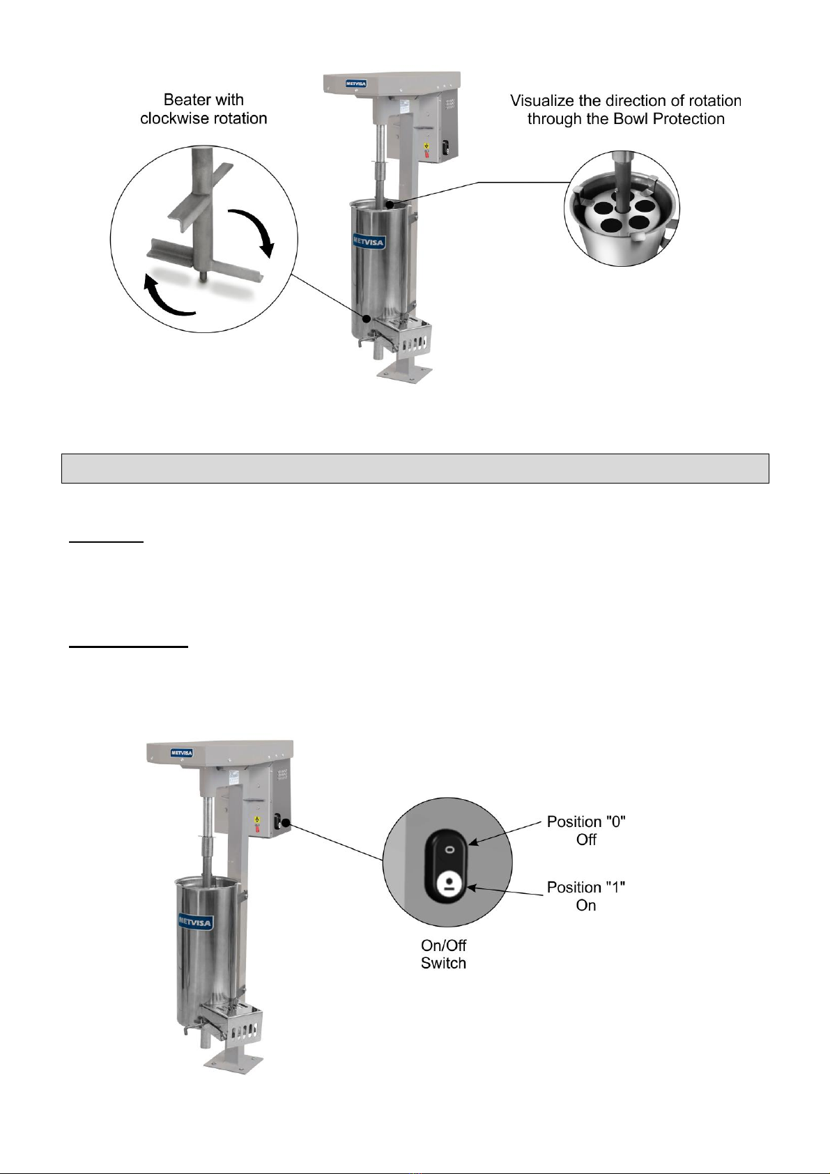
• Never place your hands, fingers or objects inside the Bowl with the power on, it might cause an
accident;
• Before you start cleaning and any maintenance, it is essential to disconnect the device from the
power network;
• Periodically check the condition of cables and electrical parts.
WARNING!
Do not make repairs yourself. Go to technical assistance authorized by the manufacturer.
Use only original parts in your device.

4
2. Technical Specifications
2.1 Main Components
To the device described in this manual, safety in use, cleaning, maintenance and maximum
hygiene are guaranteed by design and the special design of all parts, and also used stainless steel
and other suitable materials for the contact with fruit.
The device is designed with the following features:
• The Structure, Top Cover and Bottom Cover are produced in steel with epoxy paint, an excellent
anticorrosive protection;
• Axis, Semi Axis and Sleeves produced in galvanized stainless steel that protects parts from
corrosion;
• Bowl, Bowl Protection, Door, Lever, Beater and Strainer are produced in stainless steel, resistant
from attack by various corrosive agents, like most of the organic acids, organic substances in general,
alkalis, etc.
Note: Stainless steel is NOT resistant from attack by sulfuric acid, hydrochloric acid and
general chlorides and halides.
See below the main components of the device:
Note: To exploded drawing
with spare parts list, see
annexes.

5
2.2 Technical Data
Model
Nominal Measures
WidthxHeightxLength
(mm)
Net
Weight
(kg)
Voltage
(V)
Nominal
Current
(A)
Capacity
(L)
DG10110M60N4
362x1043x600
25,1
110
6,2
10
DG10220M50N1
362x1043x600
25,1
220
2,8
10
DG10220M50N2
362x1043x600
25,1
220
2,8
10
DG10220M50N4
362x1043x600
25,1
220
2,8
10
DG10220M60N4
362x1043x600
25,1
220
3,5
10
DG20110M60N4
356x1043x695
31,0
110
8,3
20
DG20220M50N1
356x1043x695
31,0
220
4,2
20
DG20220M50N2
356x1043x695
31,0
220
4,2
20
DG20220M50N4
356x1043x695
31,0
220
4,2
20
DG20220M60N4
356x1043x695
31,0
220
4,8
20
WARNING!
Features such as model, serial No. and electrical device voltage are indicated on the data
label (figure below). Before installation check if device’s voltage is according to the
electrical outlet.
3. Installation
3.1 Device Layout
The connection to the Electrical Outlet and the arrangement for the operation must be
performed by a qualified professional. Check if the device voltage is according to the electrical outlet.
During installation, it is essential to indicate this manual for the professionals who will make
it.
The device’s Base must be bolted on a plan surface, well leveled, dry and stable, away from
sources of heat and water taps. Install your device leaving a distance of at least 30 cm around it, and
with 1,30 m of high, enough space to perform inspection, maintenance, cleaning and use.

6
WARNING!
The installation and the place where it will be set must comply with the rules of prevention
of risk and safety at work (Regulatory Standard present on your country).
The manufacturer is not responsible for possible direct or indirect damages caused by non-
compliance with rules and instructions in this manual.
3.2 Electrical Connection
The device is supplied with a power cable to be connected to an electrical outlet. If the power
cable is damaged, it must be replaced by a new cable. The exchange must be carried out by the
manufacturer, dealer or qualified person in order to avoid risks.
The power cord plug varies depending on the country. The installation of the device must be
done by a technician qualified for this function and always observing the current regulatory standard
of the country, in special about ground connection (if applicable).
The equipments are supplied with an equipotential grounding terminal located in the case,
near the structure of the appliance.
The post identified in the figure below is an additional guard for the
grounding that is provided in the mains, it must be connected to a
grounding terminal bar, regardless of the connection to the mains, and
other products that have accessible metallic parts. And which are stationary, must also be
connected to this bus as well as the service bench itself, in case it is of metallic material . In
this way all these products will be under the same electrical potential avoiding undesirable
currents of leakage.

7
All device’s models described on this manual are single phase and mono-voltage, it is, 110 V
or 220 V. If necessary to change device’s voltage contact manufacturer or dealer.
WARNING!
Before connecting your device, always checks if the main supply voltage is the same as the
device voltage.
The device supply voltage is 110 V (60 Hz) or 220 V (50 Hz or 60 Hz), as can be seen in the
voltage label pasted on the power cord or as indicated on the identification label, which is
on the back of the device (see figure of this label in item 2.2 of this manual).
Make sure that the main voltage where the device will be installed is compatible with the
voltage shown in those labels.
For more details about the electrical part of the device, see the wiring diagram in the
manual.
IMPORTANT
The manufacturer is not responsible for possible direct or indirect damages caused by non-
compliance with rules and instructions in this manual.
3.3 Security Measures and User Instructions
The professional who sell the device must instruct the user about the correct operation and
must deliver him this instruction manual.
The user must be informed about the necessary safety measures and have to respect them,
and also respect all the measures described in this manual.
Your appliance has mechanical protections (see item 1.2 Mechanical Safety) that prevent
access to moving parts and electrical components. Removal or tampering with these safety
components can cause serious risks to the operator's upper limbs.
ATENÇÃO!
Before operating your appliance, check the direction of rotation of the beater .
Turn on the appliance and view through the bowl protection if the beater is rotating clockwise
as shown below.
If the beater is rotating counterclockwise, refer to the wiring diagram in item 6 Attachments or
contact your nearest authorized service center.

8
4. Device’s Use
4.1 Utility
This device was made only to extract pulp of Açaí and similar fruits.
4.2 Commands
The devide consists of only an On/Off switch located on the side of the case.

9
See description of each button:
• On/Off Switch –used to turn on an off the device. In position "1" turn on, in position "0" turn off.
4.3 Operating Procedures
Before operating your device, perform a cleaning of components that have contact with pulp
(Bowl, Bowl Protection, Strainers, Beater, etc.), to do so make sure that the device is disconnected
from the power outlet, then disassemble. Follow the cleaning instructions in section 5 of this manual.
Check the assembly and disassembly procedure described below.
• Disassembly:

10
• Assembly: The assembly procedure is the reverse of removal. When remounting the Strainer,
choose the suitable model to the process and mount it on the bottom of the Bowl with fold down. Use
screws and nuts to lock the Bowl Support on device’s structure. Mount the Beater’s Ledge on the
Strainer Hole. With one hand, lift the Bowl Protection and with the other hand mount the Beater on
Semi Axis. Mount the Protection inside the Bowl. Remove the Clamp to down the Sleeve, and then
remount the Clamp to lock the Sleeve. All parts must be mounted perfectly to avoid clamping or
abrasion, and to guarantee operator’s safety.
If any part has not been properly seated, repeat the operation and if not getting success,
contact technical assistance.

11
WARNING!
Never turn on the device with the Beater, Bowl or Bowl Protection out of position, because it
could cause accidents.
• Operation: Before turning on the device, be sure that the demountable components (Bowl, Beater e
Strainer) are well seated, the Door is locked by the Lever, and the device’s voltage is according to the
electrical outlet.
After verified all those items, follow the operation procedures:
•Connect the power cord to the electrical outlet;
• Set a container down the Bowl to store the pulp that exits from the Tube;
• Add fruits and some water;
• Turn the power switch to "1" (on), at which point the beater begins to rotate. Leave the appliance on
for a few seconds;
• Keep adding water until stops exiting pulp from the Bowl Tube;
• Place another container down the Gutter to collect waste from process;
• While device is turned on, open the Bowl Door using the Lever and add water on the Bowl to remove
all waste through the Gutter;
• After the process finishes, press position “0” (OFF) on the On/Off Switch.
WARNING!
Keep your device turned on when refill the Bowl with fruits.
If the device cannot process the pulp or stops processing, reduce the quantity of fruits,
before inserting on the Bowl. Do this not to prejudice speed and performance of the electric
motor, and the life cycle of the device.
WARNING!
Never place hands, fingers or objects (spoons and knifes) through Bowl Protection and on
other mobile parts while device is turned on, it might cause an accident.
Any irregularity contact the nearest authorized service.

12
IMPORTANT
The operator must use the appropriate PPE (personal protective equipment). For example:
use cap in hair preventing it from locking up in moving parts and appropriate gloves to
guarantee hygiene when handling fruits, also protects the operator during the pulp
processing.
5. Cleaning and Maintenance
5.1 Procedures for Cleaning and Products to be used
Your device was built with first class materials, so use it correctly and get great satisfaction.
Keep it always clean and well maintained, by doing this, your device will have longer life cycle.
You must do daily cleaning on the device for a good operation and durability.
WARNING!
Before performing maintenance or cleaning, ensure that the On/Off Switch is in position "0"
(off) and that the plug is disconnected from the mains.
WARNING!
Do not use water jet to clean the device.
IMPORTANT
This device is not intended to be fully immersed in water for cleaning.
Follow the instructions below to learn which parts can be immersed and which one needs
special care.
Demountable parts (Bowl, Strainers and Beater) should be removed from the device and
washed with water and soap. Thoroughly clean the corners, eliminating waste from the food.
When washing the Beater but the waste stills on Bowl Protection and it is necessary to remove
the Protection, loose the screws from Beater Axis using appropriate tool.
The device must be cleaned as many times as possible, to prevent dry food waste from
sticking on parts. For cleaning, dilute soap or mild detergent in warm water and apply with a soft cloth.
With a cloth humidified with water rinse the device and then, dry the parts with a soft dry cloth.
Never use abrasive products or sponges and substances containing acids or chlorine to clean
the metal parts, as they may scratch or damage the surface of the parts causing corrosion. Do not
spill water on the engine and electrical parts for cleaning, otherwise, turning it on may cause electric
shock or even burn the unit.

13
WARNING!
Once the cleaning of the Bowl Protection is finished, reset the Protection and the screws on
the Beater Axis.
Never operate the device without the Bowl Protection locked with screws and seated on the
Bowl, it might cause an accident.
IMPORTANT
The manufacturer is not responsible for possible direct or indirect damages caused by non-
compliance with rules and instructions in this manual.
WARNING!
It is extremely important that the products used in cleaning ensure maximum hygiene and
are nontoxic.

14
6. ANNEX
Wiring Diagram

15
Exploded Drawing

16
Spare Parts List
Posição
Código
Descrição
Quant.
Aplicação para o Modelo
1
CJT911
Assemble Structure
1.1
ETR130
Structure
01
*
1.2
ROL006
Bearing
02
*
1.3
EIX047
Semi Axis
01
*
1.4
APE004
Locking Ring
01
*
1.5
PNL009
Elastic Pin
01
*
1.6
LUV005
Sleeve
01
*
2
CRC1040
Bottom Cover
01
*
3
MTE283
Electric Motor 1/3 cv –127 V –60 Hz
01
DG.10
MTE284
Electric Motor 1/3 cv –220 V –60 Hz
MTE030
Electric Motor 1/3 cv –220 V –50 Hz
MTE285
Electric Motor 1/2 cv –127 V –60 Hz
01
DG.20
MTE286
Electric Motor 1/2 cv –220 V –60 Hz
MTE003
Electric Motor 1/2 cv –220 V –50 Hz
4
POL003
Pulley
01
*
5
GAB191
Case
01
*
6
PMT007
Motor Pulley
01
*
7
COR037
Belt
01
*
8
CJT123
Beater
01
DG.10
MTR004
DG.20
9
EIX108
Semi Axis
01
*
10
BOJ011
Bowl
01
DG.10
BOJ012
DG.20
11
PIA008
Strainer Ø 1,8 mm
01
DG.10
PIA011
DG.20
PIA007
Strainer Ø 1 mm
01
DG.10
PIA010
DG.20
12
CJT913
Assemble Door
01
DG.10
CJT914
DG.20
12.1
ALV006
Lever
01
*
12.2
ARL039
Flat Washer
02
*
12.3
BCH041
Door Rubber
01
DG.10
BCH040
DG.20
12.4
CRC068
Door
01
DG.10
CJT243
DG.20
12.5
POS139
Screw
03
*
12.6
PRR011
Screw
01
*
13
BCH042
Door Spacer
02
*
14
TAP151
Top Cover
01
*
15
PRR010
Screw
02
*
16
POS020
Hex Nut
03
*
17
TCE021
Rubber Eyelet Small
01
DG.10 / DG.20 ( 220 V)
TCE022
Rubber Eyelet Big
01
DG.20 ( 127 V)
18
CBE023
Electric Cable –Model 01
01
DG.10/20 - 220 V 50 Hz
CBE029
Electric Cable –Model 02
DG.10/20 - 220 V 50 Hz
CBE001
Electric Cable –Model 04
DG.10 - 110 V 60 Hz
CBE002
Electric Cable –Model 04
DG.20 - 110 V 60 Hz
CBE030
Electric Cable –Model 04
DG.10/20 220 V 50 e 60 Hz
19
RBT001
Rivet
22
*
20
PRA008
Screw
02
*
21
CHE064
On/Off Switch
01
*
22
CRC1176
Shielding Sheet
02
*
23
ARL003
Flat Washer
08
*
24
POS004
Hex Nut
10
*
25
PRS012
Screw
02
*
26
PRL006
Clamp
01
*
27
PTC062
Bowl Protection
01
DG.10
PTC069
DG.20
28
PRN001
Screw
03
*
29
PRF002
Screw
02
*
30
ARL004
Flat Washer
04
*
31
POS005
Hex Nut
03
*
32
BCH058
On/Off Switch Frame
01
*
33
SBT360
Rubber Eyelet Holder –Small
01
*
SBT361
Rubber Eyelet Holder –Big
01
*
34
RBT004
Rivet
02
*
35
CJT386
Terminal
01
*
36
TCE007
Grounding Terminal
01
*
37
PRR020
Screw
01
*
38
PRS037
Screw
01
*
39
PTC153
Top Gutter Protection
01
DG.10
PTC154
01
DG.20
40
POS018
Hex Nut
02
*
41
FIA008
Plastic Clamp
01
*
42
TCE004
Fit Terminal
04
*
43
CBE083
Electric Cable Amendment
02
*
* Item applicable to all Fruit Pulp Engine models.

17
Notes

18
Notes

19
This manual suits for next models
11
Table of contents
Other BIMG Commercial Food Equipment manuals