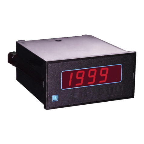
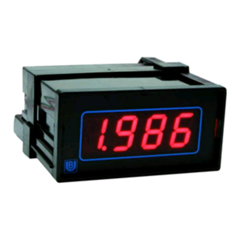
Binding Union UNICO 93 Series User manual

Binding Union s.r.l.
STRUMENTI DI MISURA
UNICO 93
series
A1 A2 HI LO HD UNICO
%
RESETHOLDPEAKAL2AL1
MEASURE SELECT ENTER
TECHNICAL MANUAL

Technical Manual (mtu9300.doc48)
BINDING UNION srl - via Cuorgnè, 21 - 10156 Torino - Italy - Tel. +39 - 011 - 2625414 - Fax +39 - 011 - 2625428 - E-mail binding@binding.it
www.binding.it
2
MICRO 93
Sommario - Summary
1. INTRODUZIONE - INTRODUCTION ........................................................................................3
2. IDENTIFICAZIONE MODELLO - MODEL IDENTIFICATION ..................................................4
3. CARATTERISTICHE TECNICHE - TECHNICAL SPECIFICATIONS ......................................5
4. FUNZIONI - FUNCTIONS.........................................................................................................5
5. INSTALLAZIONE - INSTALLATION.........................................................................................6
6. CONNESSIONI ELETTRICHE - ELECTRICAL CONNECTION...............................................7
7. MODO OPERATIVO - OPERATING MODE.............................................................................8
8. MODO PROGRAMMAZIONE - PROGRAMMING MODE........................................................9
9. SIGNIFICATO DELLE FUNZIONI - PURPOSE OF FUNCTION ...........................................11
10. OPZIONI - OPTIONS..............................................................................................................14

Technical Manual (mtu9300.doc48)
BINDING UNION srl - via Cuorgnè, 21 - 10156 Torino - Italy - Tel. +39 - 011 - 2625414 - Fax +39 - 011 - 2625428 - E-mail binding@binding.it
www.binding.it
3
MICRO 93
INTRODUZIONE INTRODUCTION
Vi ringraziamo per la scelta che avete effettuato
acquistando la nostra apparecchiatura. Questo
strumento è uno nell’ampia gamma di indicatori,
trasmettitori e sistemi di misura da noi prodotti. Saremo
lieti di inviarVi, se lo desiderate, il nostro “Catalogo
Generale”.
Per usare correttamente questo prodotto e sfruttare al
massimo le sue funzioni, Vi consigliamo di leggere
attentamente questo manuale prima dell’utilizzo.
L’ indicatore UNICO 93 è una apparecchiatura
altamente sofisticata che offre prestazioni di notevole
rilievo adatte a soddisfare anche gli utilizzatori più
esigenti.
Lo strumento utilizza largamente componenti elettronici
allo stato dell'arte e si avvale dell' uso di un
microprocessore HCMOS (High Speed CMOS), che
consente una notevole velocità di elaborazione ed
ottime capacità di calcolo.
Le sue caratteristiche standard sono:
•funzionamento a microprocessore HCMOS
•circuiti campionatori ad alta velocità
•autocalibrazione dei circuiti di acquisizione
•autozero dei comparatori di ingresso
•autodiagnosi delle funzioni interne
•circuiti di ingresso con banda passante
programmabile tramite filtro di media digitale
•programmabilità tramite tastiera di tutte le funzioni
operative
•protezione accesso alla programmazione
•possibilità di misurazione diretta dei segnali in
ingresso (misurazione "sul campo")
•due soglie di allarme open-collector configurabili
per pilotaggio relè esterni
•visualizzazione dei picchi minimo e massimo
•configurazione delle opzioni tramite tastiera
•ritenzione dei dati in assenza di alimentazione
tramite memoria non volatile (EEPROM)
•possibilità funzione di Tara
•alimentazione ausiliaria per sensori e trasduttori
•alimentazione standard 90...270 Vac switching
•uscite BCD parallele optoisolate, possibilità di
configurazione delle uscite BCD in sistema multiplo
indirizzabile (opzione)
•possibilità di alimentazione isolata in continua
10...40Vdc (opzione)
We thank you very much for purchasing our item.
This instrument is one among the wide range of displays,
transmitters and measuring devices of our production. If
you wish to have more information, we will be glad to
send you our “General Catalog”.
In order to use this product correctly and enjoy its full
benefits, please read this instruction manual carefully
before initial operations.
Unico 93 instrument is a highly sophisticated instrument
which incorporates significant performance features
targeted at the most demanding applications
The instrument uses state-of-the-art technology including
an HCMOS (High Speed CMOS) microprocessor which
results in high processing speed and excellent overall
performance.
The major features of the instrument are summarized
below:
•HCMOS microprocessor based
•high-speed sampling circuitry
•self-calibrating acquisition circuitry
•autozero of input comparators
•self-test of internal functions
•programmable bandwidth on input achieved with
digital averaging filter
•keyboard programmability of all operational functions
•password protection for access to the programmable
functions
•direct measurement capability of the input signals
(i.e. “in-the-field” measurements)
•two completely configurable open collector alarm
thresholds
•display of max/min levels of the measured signal
•keyboard configurability of the options
•data storage in non-volatile memory (EEPROM)
during power loss/removal
•tare function
•auxiliary power supply output for sensors and
transducers
•standard power supply 90...270Vac switching
•opto-isolated parallel BCD output, supports
connection of the BCD outputs in an individually
addressable multi-drop system (optional)
•may be powered from an isolated DC supply at
10...40Vdc (optional)

Technical Manual (mtu9300.doc48)
BINDING UNION srl - via Cuorgnè, 21 - 10156 Torino - Italy - Tel. +39 - 011 - 2625414 - Fax +39 - 011 - 2625428 - E-mail binding@binding.it
www.binding.it
4
MICRO 93
IDENTIFICAZIONE IDENTIFICATION
A1 A2 HI LO HD
RESETHOLDPEAKAL2AL1
MEASURE SELECT ENTER
TX RX
A
B
Ogni indicatore ha una etichetta
collegamenti (B) in poliestere metallizzato,
isolata, autoestinguente, con stampa
indelebile all’acqua, riportante i dati per
l’identificazione del modello,
l’alimentazione ausiliaria, il numero di
matricola assegnato, il campo di misura,
l’eventuale opzione interna e la
descrizione dei morsetti disponibili.
Inoltre in dotazione vengono fornite 15
etichette (A) complete di unità
ingegneristiche.
A = Engineering unit labels
mA mV A V
°C Hz %RH %
WkW kg/cm2
mbar bar mmHg
L1
Each indicator is supplied with a
connection label (B) made of metallized
polyester, nonconducting, self
extinguishing, water resistant print, with
the following data: model identification,
auxiliary supply, serial number, range,
internal options and description of
available pins.
Instrument is provided with 15
Engineering unit labels
Code INSTRUMENTS Range Accuracy Input Impedance Protection
9304 Signal processing 0/4...20 mA 0.05% 100
Ω
±
50 mA
9310 DC Voltmeter 0....2 V 0.05% 1 M
Ω
±
10 V
9312 DC Voltmeter 0....20 V 0.05% 1 M
Ω
±
100 V
9313 DC Voltmeter 0....200 V 0.05% 1 M
Ω
±
300 V
9314 DC Voltmeter 0....500 V 0.05% 1 M
Ω
±
800 V
Code POWER Code OPTIONS
S Standard 90...270Vac 00 None
K Optional 10...30Vdc / Vac 10 Programmation
11 Neutral executions
12 Custom design
49 Remote HOLD function for BCD
68 BCD output
91 Tropicalization Treatment
95 Conformity certificate
99 Binding Union calibration certificate

Technical Manual (mtu9300.doc48)
BINDING UNION srl - via Cuorgnè, 21 - 10156 Torino - Italy - Tel. +39 - 011 - 2625414 - Fax +39 - 011 - 2625428 - E-mail binding@binding.it
www.binding.it
5
MICRO 93
CARATTERISTICHE SPECIFICATIONS
caratteristiche generali general specification
Tecnica di conversione : Integrazione doppia rampa
Regolazione dello zero : automatica ad ogni ciclo
Precisione : 0.05% ±1 digit
CMRR : 86dB typ.
Linearità : ±1 LSB typ.
Coefficiente di temperatura : 5ppm /°C (5-50°C)
Banda passante : 15.9 Hz ±10%
Frequenza di campionamento : 12.5 Hz
Tempo di conversione : 80 ms
Aggiornamento lettura : da 1:1 a 100:1
Uscita allarmi : 0.1A 45Vdc Open collector
Isteresi allarmi : da 0 a 999 digit
Ritardo allarmi : da 0 a 9 sec.
Punti decimali : 5
Indicazione fuori scala : OFL / -OFL
Impostazione parametri : tramite tastiera frontale
Blocco della lettura : attivabile da tastiera
Visualizzazione picchi : massimo e minimo
Alimentazione sensori : 24Vdc ±4% 30mA max.
Peso : 400grammi
Categoria d’installazione : (cat. di sovratensioni) II
Grado inquinamento : 2 (CEI EN61010-1)
Conversion technique : dual slope integration
Zero control : automatic every cycle
Accuracy : 0.05%
±
1 digit
CMRR : 86dB typ.
Linearity :
±
1 LSB typ.
Temperature coefficient : 5ppm/°C (5-50°C)
Bandwidth : 15.9 Hz
±
10%
Sampling frequency : 12.5 Hz
Conversion time : 80 ms
Reading update : from 1:1 to 100:1
Alarms output : 0.1A 45Vdc Open collector
Alarms hysteresis : from 0 to 999 digit
Alarms delay : from 0 to 9 sec.
Decimal points : up to 5
Display Over range : OFL/-OFL
Parameters programming : by keyboard
Reading hold : by keyboard
Peaks displaying : maximum and minimum
Sensors power supply : 24Vdc
±
4% 30 mA max.
Weight : 400 grams
Installation category : (overvoltage category) II
Pollution degree : 2 (CEI EN61010-1)
FUNZIONI FUNCTIONS
MEASURE
A1 A2 HI LO HD TX RX
PEAK
SELECT
HOLD
ENTER
RESET
AL 2AL 1
ANNOUNCERS
OPERATE MODE
COMMANDS
PROGRAM MODE
COMMANDS
DECIMAL
POINT
KEYBOARD
DIGIT 5 DIGIT 4 DIGIT 3 DIGIT 2 DIGIT 1
pannello frontale front panel
In Figura 3 è mostrato il pannello frontale dello strumento
che include sette annunciatori di rispettivi eventi, cinque
digit per la visualizzazione dei dati e una tastiera
composta da cinque pulsanti per l' immissione o il
controllo dei parametri operativi. Ogni pulsante della
tastiera ha una doppia funzione ed assume un significato
diverso in relazione al modo di funzionamento. Nel
MODO OPERATIVO la tastiera agisce secondo le
definizioni impresse al di sopra dei pulsanti mentre, nel
MODO PROGRAMMAZIONE, ne assume i significati
delle diciture sottostanti.
The instrument’s front panel is illustrated in figure and
shows the seven event announcers, five digits for data
display and one keyboard consisting of five keys for
the entry or change of operating parameters.
Each key on the keyboard has a double function, which
depends on the operating mode effective at the time of
keypress. The functions indicated above the keys are
effective when the instrument is in OPERATING
MODE, while those below the keys are active in
PROGRAMMING MODE (according to the following
chart).
annunciatori announcers
segnala l’ intervento dell’ allarme 1 A1 announcer allarm 1
segnala l’ intervento dell’ allarme 2 A2 announcer allarm 2
segnala il picco massimo di lettura HI announcer max peak
segnala il picco minimo di lettura LO announcer min peak
segnala il blocco della lettura HD announcer hold function
Annunciatore non attivo TX disabled
Annunciatore non attivo RX disabled

Technical Manual (mtu9300.doc48)
BINDING UNION srl - via Cuorgnè, 21 - 10156 Torino - Italy - Tel. +39 - 011 - 2625414 - Fax +39 - 011 - 2625428 - E-mail binding@binding.it
www.binding.it
6
MICRO 93
display (Digit) display
I display normalmente misurano il valore presente in
ingresso espresso in unità ingegneristiche
5.4.3.2.1 Display normally shows the input actual value in
engineering units.
Altezza delle cifre 14.2mm 5.4.3.2.1 Characters height : 14.2 mm
Questo display visualizza il numero 1 e il segno
negativo
5 This display shows the number 1 and minus sign
Se supera il fondo scala OFL When end scale value is exceeded
Se scende sotto l’inizio scala -OFL When bottom scale value is undergone
punti decimali decimal points
Se accesi indicano l’ inizio delle cifre decimali 5.4.3.2.1.When lighted, show beginning of decimal figures
modo operativo operating mode
Premendolo si visualizza il limite dell’allarme 1 AL1 When pressed, alarm 1 limit is shown
Premendolo si visualizza il limite dell’allarme 2 AL2 When pressed, alarm 2 limit is shown
Premendolo si visualizza il picco massimo e minimo PEAK When pressed, max and min peak is shown
Premendolo si blocca la lettura HOLD When pressed, reading is held
Premendolo abbinato al tasto PEAK permette di
resettare i picchi, se abbinato al tasto AL2 si otterrà
la visualizzazione continua del valore di picco
RESET When pressed with the PEAK key, it allows to
reset peaks; when pressed with the AL2 key,
peak value will be continously displayed.
modo programmazione programming mode
Aumenta il valore della cifra selezionata (0...9) ÏIt increases the value of the selected figure (0..9)
Seleziona la cifra da modificare tra i digit 5 4 3 2 1 ÎIt selects the figure to be changed among the
digits : 5 4 3 2 1
Misura il valore in ingresso e lo acquisisce come
inizio o fondo scala (InLo InHI)
MEASURE It measures the input value and uses it as bottom
or end scale value ( InLo InHI )
Seleziona la funzione desiderata SELECT It selects the wished function
Permette di entrare nella funzione selezionata ENTER It allows to enter in the selected function
INSTALLAZIONE INSTALLATION
dimensioni fig.4 dimensions
Spessore del pannello da 1...8mm Panel thickness 1...8mm
96mm
48
92+0.5
-0
45 +0.5
-0
5107mm
44
A
B
C
montaggio dello strumento mounting of the instrument
Dopo la preparazione di un foro nel luogo d’installazione,
l’indicatore viene inserito dalla parte frontale togliendo i
cursori (C) che poi, riposizionati come in origine,
serviranno per bloccare l’indicatore sul pannello.
After practicing a hole in the place of installation,
insert the instrument by front side removing the
sliders (C) that can be used to hold the indicator on
the panel itself.
precauzioni warning
Verificare che i valori di ingresso e di alimentazione
presenti sulla “Etichetta collegamenti” corri
spondano a quelli richiesti. Controllare che tensione
e frequenza di alimentazione rientrino nelle
tolleranze previste. E’ consigliabile inserire sempre
dei fusibili di protezione sull’alimentazione. In fase
di installazione separare il cablaggio da eventuali
barre di potenza, relè, teleruttori, SCR, ecc. La
verifica scrupolosa dello schema di inserzione è
doverosa in quanto banali errori di collegamento
possono danneggiare a volte irreparabilmente lo
strumento
.
Check out that input values and power supply
indicated in the “Wiring Label” correspond to the
order. Check that main voltage and frequency lay
within the tolerance boundaries. It is always
advisable to insert protection fuse on the power
supply. During installation never run the signal
cables in the same conduit or raceway with AC
power lines, conductors that feed motors,
solenoids, SCR controls, that must be kept apart
from relays, contactors, transformers. It is advisable
to check carefully the connection diagrams,
because even banal connections faults may result
in serious damage or may even destroy the
instrument.

Technical Manual (mtu9300.doc48)
BINDING UNION srl - via Cuorgnè, 21 - 10156 Torino - Italy - Tel. +39 - 011 - 2625414 - Fax +39 - 011 - 2625428 - E-mail binding@binding.it
www.binding.it
7
MICRO 93
CONNESSIONI ELETTRICHE ELECTRICAL CONNECTION
alimentazioni power supply
L’alimentazione alternata (codice S) si collega ai
morsetti 11 (GND), 12 (L), 13 (N). L’alimentazione in
continua (codice K) si collega ai morsetti 11 (GND) 12
(+) 13 (-). Lo strumento utilizza alimentatori switching
ad alta frequenza con ingresso a range esteso. Al fine
di garantire i livelli di disturbo previsti dalle attuali
norme CE relative alla compatibilità elettromagnetica,
si raccomanda di collegare il morsetto di massa dello
strumento (morsetto n° 11) ad una efficace presa di
terra .
Alimentazione standard (S):90...270 Vac 50....60Hz
Potenza assorbita : ≤4 VA
Rigidità dielettrica : ≥2300 Vac 50 Hz
Resistenza isolamento : ≥100 Mohm
Alimentazione opzionale (K) : 10....30 Vdc / Vac
Potenza assorbita : ≤3 W
Corrente di spunto : ≤1.5A
Rigidità dielettrica : ≥500 Vac
Resistenza di isolamento : ≥100MO
AC power supply (code S) has to be connected to
terminal boards 11(GND), 12 (L), 13 (N). DC power
supply (code K) has to be connected to terminal
boards 11(GND), 12 (+), 13 (-).
The instrument is powered by a high frequency
switching power supply with universal input. To
guarantee the EMC requirements of European
Standard CE , we recommend to connect the
instrument ground terminal (terminal board n° 11) to an
effective earth .
Standard power supply (S) : 90...270 Vac 50....60Hz
Power :
≤
4 VA
Dielectrical strength :
≥
2300 Vac 50 Hz
Insulation resistance :
≥
100 Mohm
Optional power supply (K) : 10....30 Vdc / Vac
Power :
≤
3 W
Inrush current :
≤
1.5A
Dielectrical strength :
≥
500 Vac
Insulation resistance :
≥
100MO
MODEL 9310 MODELS 9312 - 9313 - 9314
0...1.9999 Vdc differential input
PROGRAMMING
1234 13
POWER
7
ALARM
56 8 1291011
12
V.out(-)
V.out(+)
N
L
INLO
COM
INHI
GND
19.999 Vdc - 199.99 Vdc - 500.0 Vdc
PROGRAMMING
1234 13
POWER
7
ALARM
56 8 1291011
1
2
V.out(-)
V.out(+)
N
L
-V IN
+V IN
GND
MODEL 9304 Alarm connection MODEL 9304
PROGRAMMING
1234 13
POWER
7
ALARM
56 8 1291011
1
2
V.out(-)
V.out(+)
N
L
-mA IN
+mA IN
GND
456789
RL2 RL1
+V
-V
PROGRAMMING
1234 13
POWER
7
ALARM
56 8 12
91011
1
2
L
transmitter
2 wire
(-)
(+)
GND
N
Per ingresso 4...20 mA programmare InLO
= 4000. Lo schema di sinistra si riferisce al
collegamento come milliamperometro e
strumento di processo. Lo schema di destra
riguarda l’utilizzo con trasmettitori o sensori
che utilizzano la tecnica due fili, in questo
caso lo strumento funge anche da
alimentatore
Schema collegamento
allarmi per pilotaggio relè
esterni
Electrical connection for
external relay
For input 4...20 mA programming InLO =
4000. Diagram on the left refers to the
connections as milliamperometer or process
instrument. Diagram on the right is for
transmitters or sensors that employ two
wires technique. In this case the instrument
supplies the transmitter.

Technical Manual (mtu9300.doc48)
BINDING UNION srl - via Cuorgnè, 21 - 10156 Torino - Italy - Tel. +39 - 011 - 2625414 - Fax +39 - 011 - 2625428 - E-mail binding@binding.it
www.binding.it
8
MICRO 93
MODO OPERATIVO OPERATING MODE
autodiagnosi self test
All’accensione lo strumento esegue automaticamente
l’autodiagnosi a l’autocalibrazione. Questa fase dura
circa 1 secondo e viene rappresentata sul display dal
messaggio “SELF”. Se il test di calibrazione viene
superato positivamente lo strumento entrerà nel
“MODO OPERATIVO” ed inizierà a visualizzare i valori
acquisiti. Diversamente l’indicazione “SELF” rimarrà
visualizzata in modo permanente indicando un guasto.
Once powered, instrument automatically performs self
test and autocalibration. This phase lasts about one
second and its result is shown on the display by the
message “SELF”. If self test is okay the instrument
enters the “OPERATING MODE” showing the acquired
values. On the contrary, if the message “SELF” is
continuously displayed, a failure is occurring.
modo operativo operating mode
Nel modo operativo lo strumento esegue la misura
della grandezza fisica in ingresso secondo le
predisposizioni programmate dall’utente. Tuttavia sono
possibili alcune operazioni di verifica e controllo
agendo sulla tastiera del pannello frontale.
a) Verifica soglia Allarme 1. Alla pressione del
pulsante “AL1” il display presenterà il valore di soglia
impostato per l’allarme 1. Al rilascio del pulsante verrà
ripristinato il valore della grandezza in ingresso.
b) Verifica soglia Allarme 2. Come sopra ma
premendo “AL2”.
c) Lettura dei valori di picco minimo e massimo. Il
pulsante “PEAK” permette la visualizzazione ciclica di
entrambi i valori. Premendo una prima volta il pulsante
“PEAK” si accenderà l’annunciatore “Hi” indicando che
la lettura si riferisce al valore massimo. Rilasciando il
pulsante verrà ripristinato il valore della grandezza in
ingresso. Premendo una seconda volta il pulsante
“PEAK” si accenderà l’annunciatore “Lo” e sul display
verrà visualizzato il valore di picco minimo.
N.B. Premendo contemporaneamente i pulsanti
“RESET” e “AL2” si otterrà la visualizzazione continua
del valore di picco massimo sul display (segnalata
dall’accensione dell’annunciaore “HI”), premendoli una
seconda volta si visualizzerà il valore del picco minimo
(accensione annunciatore “LO”). Quando è abilitata
questa funzione i pulsanti frontali non sono operativi se
non per tornare al modo programmazione. Per tornare
al funzionamento normale senza perdere i valori di
picco è sufficiente entrare ed uscire dalla
programmazione.
d) Azzeramento dei valori di picco. L’azzeramento dei
valori di picco avviene mantenendo premuto il tasto
“RESET” e premendo il tasto “PEAK”.
e) Sospensione aggiornamento display (Hold).
Premendo il tasto “HOLD” si accende l’annunciatore
“HD” e si sospende l’aggiornamento del display. Il
pulsante “HOLD” e di tipo bistabile cioè ad una prima
pressione sospende l’aggiornamento, mentre ad una
successiva pressione lo ripristina.
f) Segnalazione superamento soglie di allarme. I due
annunciatori “A1” e “A2” relativi agli allarmi 1 e 2
indicano, quando accesi, che la corrispondente soglia
e’ stata superata.
In operating mode the instrument performs the
measurement of the input value according to the user’s
settings. Nevertheless, it is possible to make some
controls simply using the front panel keyboard.
a) Alarm 1 threshold check. By pressing “AL1”key the
display shows the threshold setting for alarm 1. If the key
is depressed the display shows again the normal input
value.
b) Alarm 2 threshold check. As for alarm 1 but pressing
“AL2”.
c) Maximum and Minimum Peak. “PEAK” key allow the
cyclic reading of both minimum and maximum peak
values. If “PEAK” key is pressed once the “Hi” announcer
turns on, meaning that the reading refers to the maximum
peak value. By depressing “PEAK” key the display shows
again the normal input value.
If “PEAK” key is pressed a second time the “Lo”
announcer turns, the display will show the minimum peak
value.
NOTICE
Maximum peak value is continuously displayed by
pressing “RESET” and “AL2” together (announcer “HI” is
on ), while minimum peak value is continuously displayed
by pressing together the same keys a second time
(announcer “LO” is on ). When this function is enabled,
front keys are not available but for going back to the
programming mode. Normal operating mode without losing
peak values is achievable by making a programming
cycle.
d) Peak value reset. Peak value reset is performed by
holding “RESET” key on and by pressing “PEAK” key.
e) Display hold. If “HOLD” key is pressed the announcer
“HD” turns on and the display updating is stopped.
”HOLD” key is a bistable type that performs the hold
function at the first pressing while allows the display
updating at the second pressing.
f) Alarm over threshold . Announcers “A1” and “A2”
represent the status of the alarms 1 and 2 and show, when
they are on, that the corresponding threshold has been
overcome.

Technical Manual (mtu9300.doc48)
BINDING UNION srl - via Cuorgnè, 21 - 10156 Torino - Italy - Tel. +39 - 011 - 2625414 - Fax +39 - 011 - 2625428 - E-mail binding@binding.it
www.binding.it
9
MICRO 93
MODO PROGRAMMAZIONE PROGRAMMING MODE
Per modificare le predisposizioni interne dello
strumento e’ necessario entrare nel modo
programmazio ne. Tale operazione si effettua
mantenendo premuto il tasto “RESET” e premendo il
tasto “HOLD”. A questo punto sul display comparirà la
richiesta di password con il messaggio “PASS”.
Rilasciando i pulsanti “HOLD“ e “RESET” il display
presenterà la password di default “ - - - - ” ed aspetterà
l’immissione, tramite i pulsanti Ïe Îdella password
definita dall’utilizzatore. Se non si desidera inserire una
password è sufficiente passare alla voce successiva
usando il tasto “SELECT”. Il funzionamento dei tasti
Ïe Îsegue le regole del “ROLLING MODE” . Se la
password e’ corretta , la successiva pressione del
pulsante “SELECT” permetterà di accedere alle
funzioni interne dello strumento, diversamente
comparirà il messaggio “FAIL” e dopo circa un
secondo lo strumento ritornerà nel modo operativo.
a) Implementazione delle funzioni interne. Le funzio
ni interne vengono selezionate agendo sul pulsante
“SELECT” sul display compariranno i nomi delle
funzioni interne nell’ordine riportato nella
“PROGRAMMING TABLE” .
b) Modifica dei parametri. Per modificare uno
specifico parametro di una funzione e’ necessario
selezionare la funzione con il tasto “SELECT” ed
attivare il programma di modifica tramite il tasto
“ENTER” .
In questo modo il display indicherà il parametro
associato alla funzione. Se il parametro e’
predeterminato esso sarà modificabile agendo sul
pulsante Ïmentre se e’ selezionabile sarà modificabile
tramite i pulsanti Ïe Îe potrà assumere qualsiasi
valore numerico.
c) Memorizzazione dei parametri. La
memorizzazione del parametro modificato avviene con
la pressione del tasto “SELECT” .Tale operazione
determinerà inoltre il posizionamento del display sul
nome della funzione successiva. Se il valore del
parametro modificato non e’ coerente verrà ripristinato
il valore precedente. Se non si desidera modificare il
parametro di una determinata funzione e’ sufficiente
premere il pulsante “SELECT” senza agire sui
pulsanti Ïe Î
d) Uscita dal modo programmazione. Per ritornare
al modo operativo e’ necessario mantenere premuto il
tasto “ENTER” e premere il tasto “SELECT”. In
questo modo sul display comparirà il messaggio
“SAVE” per indicare che i parametri modificati sono
stati salvati.
To modify instrument’s internal settings it is necessary to
enter programming mode. This operation is performed by
holding “RESET” key on and by pressing “HOLD” key . At
this time the display shows the password request with the
message “PASS” .
By depressing “HOLD” and “RESET” keys the default
password “ - - - - ” is displayed and the instrument
waits the user’s password to be entered by means of Ï
and Îkeys. The password entering can be avoided by
pressing “SELECT” key.
The operation of these keys (
Ï
and
Î
)is according to
the “ROLLING MODE” rule.
If the password is right the following actuation of
“SELECT” key allows the user to access the internal
function settings of the instrument, otherwise a “FAIL”
message is displayed and after a time of about a second
the instrument goes back to the operating mode.
a) Internal functions implementation. Internal functions
are selectable by operating “SELECT” key. The display
shows internal function names according to the order
shown in the “PROGRAMMING TABLE”.
b) Parameter adjustment. For adjusting a function
specific parameter it is necessary to select the function by
means of the “SELECT” key and to initiate the modifying
program by operating the “ENTER” key.
In this way the display shows the actual function
parameter value. If the parameter is a predetermined
type it is adjustable by using Ïkey.
If the parameter is a selectable type it is adjustable by
means of Ïand Îkeys and it may be any numerical
value selected by the user.
c) Parameter saving. For saving the modified parameter
it is necessary to operate the “SELECT” key. As a result
of this operation the display shows the name of the
function that follows. If the modified parameter value is
not coherent with the limit of the function the previous
value is shown. To avoid the saving of a modified
parameter it is necessary to operate the “SELECT” key
without using
Ï
and
Î
keys.
d) Quit programming mode. To quit programming mode
and return to operating mode hold “ENTER” key on and
press “SELECT” key. In this way the display shows the
message “SAVE” to indicate that all modified parameters
have been saved in the instrument memory.

Technical Manual (mtu9300.doc48)
BINDING UNION srl - via Cuorgnè, 21 - 10156 Torino - Italy - Tel. +39 - 011 - 2625414 - Fax +39 - 011 - 2625428 - E-mail binding@binding.it
www.binding.it
10
MICRO 93
PROGRAMMING TABLE
HPAS
- - - - no
ISEL
In 2
In 3
NEW
VALUE
0
In 1
rAr
AVEr
dECP
5
no
YES
FAIL
ENTER
SELECT
ENTER ENTER
YES
ENTER
ENTER
SELECT SELECT
SELECT SELECT
SELECT SELECT
SELECT
SELECT
SELECT InLo
0000
NEW
VALUE
ENTER
SELECT
MEASURE
SELECT
SELECT InHi
1.9999
NEW
VALUE
ENTER
SELECT
MEASURE
SELECT
SELECT
dILo
0000
NEW
VALUE
ENTER
SELECT
SELECT
SELECT dIHI
1.9999
NEW
VALUE
ENTER
SELECT
SELECT
SELECT
SELECT
SELECT
SELECT
SELECT
SELECT
SELECT
SELECT
UPdn
00
NEW
VALUE
ENTER
SELECT
SELECT
SELECT
AL1
1.9999
NEW
VALUE
ENTER
SELECT
SELECT
SELECT
POL1
UP
dn
ENTER
SELECT
SELECT
SELECT
HYS1
000
NEW
VALUE
ENTER
SELECT
SELECT
SELECT
Con1
no
YES
ENTER
dLY1
0
NEW
VALUE
ENTER
SELECT
SELECT
SELECT AL2
1.9999
NEW
VALUE
ENTER
SELECT
SELECT
SELECT POL2
UP
dn
ENTER
SELECT
SELECT
SELECT HYS2
000
NEW
VALUE
ENTER
SELECT
SELECT
SELECT Con2
no
YES
ENTER
SELECT
SELECT
SELECT dLY2
0
NEW
VALUE
ENTER
SELECT
SELECT
SELECT
Addr
00
NEW
VALUE
ENTER
SELECT
SELECT
SELECT
75
SPEd
9600
ENTER
SELECT
SELECT
SELECT
Adch
no
YES
ENTER
SELECT
SELECT
SELECT
SoLc
0000
NEW
VALUE
ENTER
SELECT
SELECT
SELECT
EoLc
0000
NEW
VALUE
ENTER
SELECT
SELECT
SELECT
OSEL
An1
An2
ENTER
SELECT
SELECT
SELECT
WRONG
PASSWORD
BACK TO
OPERATING MODE
SELECT
SELECT
SELECT

Technical Manual (mtu9300.doc48)
BINDING UNION srl - via Cuorgnè, 21 - 10156 Torino - Italy - Tel. +39 - 011 - 2625414 - Fax +39 - 011 - 2625428 - E-mail binding@binding.it
www.binding.it
11
MICRO 93
9. Significato delle funzioni Function explanation
HPAS
Password - Valore di default (- - - -) Password - Default value (- - - -)
Se si inseriscono dei simboli diversi da quelli di default l’ingresso
al Modo Programmazione viene impedito finchè non si inserisce
l’esatta Password.
If symbols other than those of Default are inserted, input to the
programming mode is inhibited, as long as the correct password
is not introduced.
Pulsanti attivi: ÏÎSELECT ENTER Active keys: ÏÎSELECT ENTER
Tipo dato inseribile: Parametro ad ingresso selezionabile Type of insertable data: Parameter with selectable input
Digit attivi: || || Digit 4 || Digit 3 || Digit 2 || Digit 1|| Active digits: || || Digit 4 || Digit 3 || Digit 2 || Digit 1|
Possibili valori digit: Qualsiasi combinazione dei caratteri: 0 1 2
3 4 5 6 7 8 9 A b C d E F blank c H h J L n o P r U u Y - = O
Digit possible values: Every character mix : 0 1 2 3 4 5 6 7 8 9
A b C d E F blank c H h J L n o P r U u Y - = O
rAr
Tara - Valore di default (no) Tare - Default value (NO)
Se abilitata (yes) permette nel normale funzionamento (modo ope
rativo) di azzerare il segnale presente agli ingressi premendo i
pulsanti RESET e AL1. Questa funzione non influisce sui valori di
taratura impostati, comportandosi quindi come una vera Tara.
When activated (yes), it allows in normal operation (operating
mode) to zero the input signal, by pressing the keys RESET and
AL1. This function does not influence the preset tare value, and
therefore behaves as a real Tare.
Pulsanti attivi: AL1 RESET Active Keys: AL1 RESET
Tipo dato inseribile: Parametro ad ingresso predeterminato Type of insertable data: Parameter with preset input
Digit attivi: || || Digit 4 || Digit 3 || Digit 2 || || Active digits: || || Digit 4 || Digit 3 || Digit 2 || ||
Possibili diciture display: yes no Possible display text: yes no
Significato diciture: yes = tara inserita no = tara disinserita Text meaning: ...yes = inserted tare no = disinserted tare
ISEL
Selezione del segnale in ingresso - funzione non abilitata Input Signal Selection - function not activated
InLo
Valore minimo del segnale in ingresso - Valore di default: 0000 Min. Input Signal value - Default value : 0000
Nel modello 9304 va impostato il numero 4000 se si intende misu
rare un segnale 4...20mA. Può ugualmente essere molto utile nel
caso in cui il segnale derivante da sensori non sia esattamente a
zero, in tal caso con segnale minimo applicato, entrare nella fun-
zione e premere il pulsante MEASURE, lo strumento misurerà il
valore presente ai suoi ingressi e lo acquisirà come valore di zero.
In the 9304 model, if you intend to measure a 4 to 20 mA signal,
you must key in 4000. It can be also very useful when the signal
delivered by the sensors, is not exactly zero. Then with min.
signal applied, enter in the function and press the key
MEASURE, the instrument will measure the actual value at its
inputa and will handle it as zero value.
Pulsanti attivi: ÏÎMEASURE SELECT ENTER Active Keys: ÏÎMEASURE SELECT ENTER
Tipo dato inseribile: Parametro ad ingresso selezionabile Type of insertable data: Parameter with selectable input
Digit attivi: || Digit 5 || Digit 4 || Digit 3 || Digit 2 || Digit 1 || Active digits: || Digit 5 || Digit 4 || Digit 3 || Digit 2 || Digit 1|
Possibili valori digit: qualsiasi combinazione 0-1-2-3-4-5-6-7-8-9 Digit possible values: Every character mix : 0 1 2 3 4 5 6 7 8 9
InHI
Valore massimo del segnale in ingresso - Valore default: 19999 Min. Input Signal value - Default value : 19999
Normalmente corrisponde al fondo scala dello strumento 19999.
Si possono compensare eventuali errori con il tasto MEASURE, il
funzionamento è uguale alla voce InLo ma con segnale massimo
applicato agli ingressi.
It normally corresponds to the instrument scale end 19999.
With the key MEASURE possible errors can be offset, operation
is the same as at position InLo, but with max signal applied to the
inputs.
Pulsanti attivi: ÏÎMEASURE SELECT ENTER Active keys: ÏÎMEASURE SELECT ENTER
Tipo dato inseribile: Parametro ad ingresso selezionabile Type of insertable data: Parameter with selectable input
Digit attivi: || Digit 5 || Digit 4 || Digit 3 || Digit 2 || Digit 1 || Active digits: || Digit 5 || Digit 4 || Digit 3 || Digit 2 || Digit 1|
Possibili valori digit: qualsiasi combinazione 0-1-2-3-4-5-6-7-8-9 Digit possible values: Every character mix : 0 1 2 3 4 5 6 7 8 9
dILo
Valore minimo del dato sul display - Valore di default: 0000 Min. data value on Display - Default value : 0000
Da utilizzare quando lo strumento deve visualizzare un valore
minimo diverso da quello in ingresso.
It must be used when the instrument must display a minimu value
other than the input one.
Pulsanti attivi: ÏÎSELECT ENTER Active Keys: ÏÎSELECT ENTER
Tipo dato inseribile: Parametro ad ingresso selezionabile Type of insertable data: Parameter with selectable input
Digit attivi: || Digit 5 || Digit 4 || Digit 3 || Digit 2 || Digit 1 || Active digits: || Digit 5 || Digit 4 || Digit 3 || Digit 2 || Digit 1|
Possibili valori digit: qualsiasi combinazione 0 1 2 3 4 5 6 7 8 9 Digit possible values: Every character mix : 0 1 2 3 4 5 6 7 8 9
dIHI
Valore massimo del dato sul display - Valore di default: 19999 Max. data value on Display - Default value : 19999
Pulsanti attivi: ÏÎSELECT ENTER Active Keys: ÏÎSELECT ENTER
Tipo dato inseribile: Parametro ad ingresso selezionabile Type of insertable data: Parameter with selectable input
Digit attivi: || Digit 5 || Digit 4 || Digit 3 || Digit 2 || Digit 1 || Active digits: || Digit 5 || Digit 4 || Digit 3 || Digit 2 || Digit 1|
Possibili valori digit: qualsiasi combinazione 0 1 2 3 4 5 6 7 8 9 Digit possible values: Every character mix : 0 1 2 3 4 5 6 7 8 9

Technical Manual (mtu9300.doc48)
BINDING UNION srl - via Cuorgnè, 21 - 10156 Torino - Italy - Tel. +39 - 011 - 2625414 - Fax +39 - 011 - 2625428 - E-mail binding@binding.it
www.binding.it
12
MICRO 93
dECP
Posizione del punto decimale sul display - Valore di default: 5 Decimal Point Position on Display - Default value: 5
Pulsanti attivi: ÏSELECT ENTER Active Keys: ÏSELECT ENTER
Tipo dato inseribile: Parametro ad ingresso selezionabile Type of insertable data: Parameter with selectable input
Digit attivi: || || || || || Digit 1 || Active digits: || || || || || Digit 1|I
Possibili valori digit: || 0 1 2 3 4 5 || Digit possible values: II 0 1 2 3 4 5 II
Significato digit: 0 = nessun punto decimale
1= punto decimale a destra digit 1 - 2 = a destra digit 2
3= a destra digit 3 - 4 = a destra digit 4 - 5= a destra digit 5
Digit meaning: 0 = no decimal point
1= decimal point,on the right to digit 1 ; 2= on the left to digit 2
3= on the right to digit 3 ; 4= on the right to digit 4 ; 5= on the
right to digit 5
AVEr
Filtro di media - Valore di default: no Averaging Filter - Default value : no
Se abilitato (yes) inserisce un filtro digitale per effettuare una
operazione di media sul valore misurato
When activated ( yes ), a digital filter is activated to average the
measured value
Pulsanti attivi: ÏSELECT ENTER Active Keys: ÏSELECT ENTER
Tipo dato inseribile: Parametro ad ingresso predeterminato Type of insertable data: Parameter with preset input
Digit attivi: || || Digit 4 || Digit 3 || Digit 2 || || Active digits: || || || Digit 4|| Digit 3 || Digit 2|I
Possibili diciture display: yes no Possible display text: yes no
Significato diciture display: yes=filtro inserito no=disinserito Meaning of display text: yes = filter active no = filter non active
Updn
Ciclo di aggiornamento del dato - Valore di default: 00 Data Updating Cycle – Default value: 00
Definisce quanti cicli di acquisizione deve effettuare lo strumento
prima di eseguire controlli ed operazioni di scalatura sul dato ed
aggiornare il display. Il tempo necessario per effettuare 1 ciclo è di
80 msec (Updn = 00) impostando Updn = 01 lo strumento
aggiornerà la visualizzazione ogni 160 msec, e cosi via.
It defines how many cycles, the instrument must perform before
making controls and scaling on the data and before refreshing
thew display. Necessary time for 1 cycle is 80 ms (Updn = 00)
while setting Updn = 01, the instrument will refresh the disply
every 160 ms and so on
Pulsanti attivi: ÏÎSELECT ENTER Active Keys: ÏÎSELECT ENTER
Tipo dato inseribile: Parametro ad ingresso selezionabile Type of insertable data: Parameter with selectable input
Digit attivi: || || || || Digit 2 || Digit 1 || Active digits: || || || || Digit 2 || Digit 1 ||
Possibili valori digit: tutte le combinazioni di 0 1 2 3 4 5 6 7 8 9 Digit possible values:– every mix of 0 1 2 3 4 5 6 7 8 9I
AL 1 / AL2
Valore di soglia degli Allarmi 1 e 2 - Valore di default: 19999 Threshold value for alarms 1 and 2 - Default value: 19999
Definisce in corrispondenza di quale valore l’allarme 1 o 2 diventa
attivo. Al superamento del valore impostato l’annunciatore
corrispondente (A1 / A2) si illumina.
It defines for which value alarm 1 or 2 becomes active. Once the
preset value is exceeded, corresponding announcer (A1/A2)
lights up.
Pulsanti attivi: ÏÎSELECT ENTER Active Keys: ÏÎSELECT ENTER
Tipo dato inseribile: Parametro ad ingresso selezionabile Type of insertable data: Parameter with selectable input
Digit attivi: || Digit 5 || Digit 4 || Digit 3 || Digit 2 || Digit 1 || Active digits: || Digit 5 || Digit 4 || Digit 3 || Digit 2 || Digit 1 |
Possibili valori digit: tutte le combinazioni di 0 1 2 3 4 5 6 7 8 9 Digit possible values: every mix of 0 1 2 3 4 5 6 7 8 9I
POL1 / POL 2
Polarità Allarme 1 e 2 - Valore di default: UP Polarity Alarm 1 and 2 - Default value: UP
Definisce la polarità dell’intervento dell’allarme UP = l’allarme sarà
attivato con valore visualizzato dallo strumento uguale o superiore
al valore impostato alla voce AL1 / AL2
dn = l’allarme sarà attivato con valore visualizzato uguale o
inferiore al valore impostato alla voce AL1/AL2
It defines to polarity of the alarm intervention : UP = alarm is
activated when the value displayed by the instrument is higher or
equal to the preset value for AL1 /AL2
Dn = alarm is activated when the value displayed by the
instrument is lower or equal to the preset value for AL1 /AL2
Pulsanti attivi: ÏSELECT ENTER Active Keys: ÏSELECT ENTER
Tipo dato inseribile: Parametro ad ingresso predeterminato Type of insertable data: Parameter with preset input
Digit attivi: || || || Digit 3 || Digit 2 || || Active digits: || || || Digit 3 || Digit 2 || |
Possibili diciture display: UP dn Possible display text: UP dn
Significato diciture display: UP = allarme di max dn = minima Meaning of display text: UP = alarm of max dn = alarm of min
HYS1 / HYS2
Isteresi Allarme 1 o 2 - Valore di default: 000 Hysteresis Alarm 1 and 2 - Default value: 000
Definisce, in relazione alla polarità selezionata, il valore in digit da
addizionare o sottrarre al valore di soglia dell’allarme (AL1 / AL2)
per consentire il ritorno alla condizione di riposo dell’allarme.
L’isteresi agisce sempre in senso contrario alla polarità
dell’allarme.
It defines in correspondence to the preset polarity the digit value
to be added or deducted to the alarm threshold value ( AL1 /AL2)
to allow the return to the alarm normal condition. Hysteresis
always acts in the versus opposite to the alarm polarity
Pulsanti attivi: ÏÎSELECT ENTER Active Keys: ÏÎSELECT ENTER
Tipo dato inseribile: Parametro ad ingresso selezionabile Type of insertable data: Parameter with selectable input
Digit attivi: || || || Digit 3 || Digit 2 || Digit 1 || Active digits: || || || Digit 3 || Digit 2 || Digit 1 |
Possibili valori digit: tutte le combinazioni di 0 1 2 3 4 5 6 7 8 9 Digit possible values: every mix of 0 1 2 3 4 5 6 7 8 9I

Technical Manual (mtu9300.doc48)
BINDING UNION srl - via Cuorgnè, 21 - 10156 Torino - Italy - Tel. +39 - 011 - 2625414 - Fax +39 - 011 - 2625428 - E-mail binding@binding.it
www.binding.it
13
MICRO 93
Con1 / Con2
Contatto Allarme 1 e 2 - Valore di default: no Alarm contact 1 and 2 – Default value: no
Abilita il comando dei relè esterni. It enables the control of external relays
Pulsanti attivi: ÏSELECT ENTER Active Keys: ÏSELECT ENTER
Tipo dato inseribile: Parametro ad ingresso predeterminato Type of insertable data: Parameter with preset input
Digit attivi: || || Digit 4 || Digit 3 || Digit 2 || || Active digits: || || Digit 4 || Digit 3 || Digit 2 ||
Possibili diciture display: yes no Possible display text: yes no
Significato diciture display:yes=contatto inserito no=disinserito Meaning of display text: yes = contact on no = contact off
dLY1 / dLY2
Ritardo intervento contatto 1 o 2 - Valore di default: 0 Delay Contact 1 and 2 – Default value: 0
Definisce dopo quanto tempo dall’evento di allarme il comando
deve azionare il relè esterno corrispondente. Questa funzione è
attiva solo se Con1 o Con2 sono abilitati. Il ritardo d’intervento va
moltiplicato per il numero di salti di ciclo impostati in Updn.
It defines the delay after the alarm event when the control must
activate the corresponding external relay. This function is only
active if Con 1 and Con 2 are enabled. Intervention delay time is
multiplied by the number of cycle jumps preset in Updn.
Pulsanti attivi: ÏSELECT ENTER Active Keys: ÏSELECT ENTER
Tipo dato inseribile: Parametro ad ingresso selezionabile Type of insertable data: Parameter with selectable input
Digit attivi: || || || || || Digit 1 || Active digits: || || || || || Digit 1 ||
Possibili valori digit: 0-1-2-3-4-5-6-7-8-9 Digit possible values: 0 1 2 3 4 5 6 7 8 9I
Addr
Indirizzo interfaccia BCD - Valore di default: 00 BCD Port Address - Default value: 00
Questa funzione è attiva solo se l’interfaccia BCD parallela
(opzioni) è installata
This function is enabled only if parallel BCD port ( option ) is
installed
Pulsanti attivi: ÏÎSELECT ENTER Active Keys: ÏÎSELECT ENTER
Tipo dato inseribile: Parametro ad ingresso selezionabile Type of insertable data: Parameter with selectable input
Digit attivi: || || || || Digit 2 || Digit 1 || Active digits: || || || || Digit 2 || Digit 1 ||
Possibili valori digit: tutte le combinazioni 0-1-2-3-4-5-6-7-8-9 Digit possible values: every mix of 0 1 2 3 4 5 6 7 8 9I
SPEd
Velocità seriale di comunicazione - funzione non abilitata Serial Port communication Speed - function not implemented
Adch
Inserzione Caratteri di testa e coda - funzione non abilitata Leading/Trailing Character Insertion -function not implemented
SoLc
Caratteri di testa - funzione non abilitata Start of Line Characters – function not implemented
EoLc
Caratteri di coda - funzione non abilitata End of Line Characters – function not implemented
OSEL
Selezione del tipo di segnale in uscita - funzione non abilitata Output Signal Selection – function not implemented
CODICI DI ERRORE DISPLAY ERROR CODES
Ingresso minimo ≥ingresso massimo E = 03 Minimum input ≥maximum input
Ingresso massimo ≤ingresso minimo E = 04 Maximum input ≤minimum input
Display minimo ≥display massimo E = 05 Display minimum ≥display maximum
Display massimo ≤display minimo E = 06 Display maximum ≤display minimum
Soglia allarme 1 fuori scala E = 10 Alarm 1 threshold out of range
Polarità allarme 1 fuori scala E = 11 Alarm 1 polarity out of range
Isteresi allarme 1 fuori scala E = 12 Alarm 1 hysteresis out of range
E = 13
E = 14
Soglia allarme 2 fuori scala E = 15 Alarm 2 threshold out of range
Polarità allarme 2 fuori scala E = 16 Alarm 2 polarity out of range
Isteresi allarme 2 fuori scala E = 17 Alarm 2 Hysteresis out of range
E = 18
E = 19
Indirizzo > 63 E = 20 Address > 63
Errore checksum in lettura E = 97 Checksum error during reading
Errore verifica dopo scrittura E = 98 Memory error after writing
Errore funzionale E = 99 Functional error

Technical Manual (mtu9300.doc48)
BINDING UNION srl - via Cuorgnè, 21 - 10156 Torino - Italy - Tel. +39 - 011 - 2625414 - Fax +39 - 011 - 2625428 - E-mail binding@binding.it
www.binding.it
14
BCD OUTPUT
OPZIONE 68 68 OPTION
1234
(+)
(-)
PWR
PWR
B
1
A
54321
AB
12 4 8
TENS
5432 6
12 4 8
UNITS
13756 8 12910 11
1561413121110987
12 4 8
10K
THOUSANDS
1110987
12 4 8 A0
HUNDREDS
15141312
A1 A2 A3 A4
ADDRESS
HOLD
DAV
OVER
POL
(18...27 Vdc)
USCITA BCD OPTO ISOLATA OPTOISOLATED BCD OUTPUT
La scheda d’interfaccia per uscite BCD (Binary Coded
Decimal) parallele permette il collegamento degli
strumenti serie 93 con apparecchiature di acquisizione
dati che interrogando lo strumento permettono la
trasmissione dei dati calcolati da Micro 93.
La scheda d’interfaccia consente inoltre la costruzione
di una rete di strumenti (fino ad un massimo di 32)
collegati in parallelo secondo il sistema Bus
Handshake.
The BCD (Binary Coded Decimal) parallel interface
output allows interconnection of the series 93
instruments with data acquisition equipment that have
BCD compatible inputs.
The BCD interface has been designed to network
series 93 instruments (up to 32) using the “Handshake
Bus” method.
caratteristiche specifications
Codice di trasmissione: BCD(Binary Coded Decimal)
Trasmissione : Bus parallelo
Metodo : Bus Handshake
Isolamento galvanico : 500 Vdc
Indirizzo interfaccia : da 0 a 31 selezionabile da
pulsantiera (funz. Addr)
Aggiornamento dei dati: ≤80 ms
Alimentazione : da 18 a 27 Vdc
Assorbimento : 15 mA max uscite OFF,
40 mA max uscite ON
Livello logico basso ingresso: min 0 V,
max 0,5 Vdc @5 µA
Livello logico alto ingresso: min 18 V,
max 35 V @ 400 µA
Livello logico basso uscita: 0.5 V max @ 5 µA sink
Livello logico alto uscita: (alimentazione - 2V) min
@ 10 mA source
Massima corrente in uscita: 50 mA source senza
protezione contro corti circuiti
Potenza dissipata : 100 mW per transistor
Output data coding : BCD (Binary Coded Decimal)
Transmission mechanism : parallel Bus
Method : Handshake Bus
Galvanic insulation : 500 Vdc
Terminal address : from 0 through 31DEC selectable
via instr. keyboard (Addr. Funct.)
Data update time :
≤
80 ms
External supply : from 18 to 27 Vdc
Consumption : 15 mA max with outputs OFF
40 mA max with outputs ON
Input logic zero level :min. 0 V, max 0.5 V @5 µA
Input logic one level : min 18 V, max 35 V @400 µA
Output logic zero level : 0.5 V max @5 µA sink
Output logic one level : (external supply value minus
2V) min @ 10 mA source
Maximum output current : 50 mA source, without
short circuit protection
Dissipated power : 100 mW for single transistor

Technical Manual (mtu9300.doc48)
BINDING UNION srl - via Cuorgnè, 21 - 10156 Torino - Italy - Tel. +39 - 011 - 2625414 - Fax +39 - 011 - 2625428 - E-mail binding@binding.it
www.binding.it
15
BCD OUTPUT
interrogazione strumento instrument polling
L’interrogazione viene effettuata inviando sulle linee di
selezione un codice corrispondente all’indirizzo dello
strumento desiderato. Alla ricezione del codice lo
strumento attiverà i buffers di comunicazione
dell’interfaccia inviando come risposta il valore
codificato in forma BCD parallela. L’interfaccia
prevede, per i sistemi che necessitano di un segnale di
sincronizzazione, una uscita “dato disponibile” DAV
(Data Available) che consente, in corrispondenza del
suo fronte di salita, l’acquisizione di dati stabilizzati
sulle linee di uscita evitando così eventuali
sovrapposizioni di informazioni (garbaged data).
Polling is performed by sending the instrument a code
corresponding to its address via the selection lines.
Upon reception of this interrogation code, the
instrument program will activate the output buffers and
thus send out its BCD coded value via the parallel
interface. For those systems requiring synchronisation
between instrument and data acquisition equipment,
the parallel interface provides a “Data Available” (DAV)
output strobe. The rising edge of this strobe pulse
indicates to external equipment that stable, valid data
is available at the instrument output interface.
comando interrogazione uscite BCD interrogate command for bcd output
A4 A3 A2 A1 A0
N4 N3 N2 N1 N0
dove / where
Bit Descrizione / Description Valori possibili / Possible value
N4 N3 N2 N1 N0 Bit determinanti l’indirizzo dell’interfaccia BCD da 00000BIN (0DEC) a 11111BIN (31DEC)
BCD parallel interface address bits 00000BIN (0DEC) through 11111BIN (31DEC)
comando data hold data hold signal
E’ possibile sospendere temporaneamente
l’aggiornamento dei dati sulle linee di uscita tramite
l’attivazione del comando Data Hold. I dati presenti
sulle linee di uscita assumeranno il valore che avevano
all’istante immediatamente precedente all’attivazione
del suddetto comando e saranno aggiornati
nuovamente quando il comando Data Hold verrà
posizionato nella condizione inattiva. L’ingresso Data
Hold è attivo a livello logico alto.
Suspension of data update is possible by means of
the Data Hold signal. When the Data Hold input to the
instrument is asserted, the parallel output lines will
maintain the value that was being output at the
moment the Data Hold input was asserted. The
instrument will resume updating the parallel output
lines when the data hold input is returned to the non-
asserted condition. The Data Hold input is asserted
when it is at the logic one level.
descrizione dati BCD BCD data description
10k : cifra più significativa mostrata dallo strumento
POL : polarità del segnale 1 = positivo, 0 = negativo
OVER : indicazione di fuori scala 1 = fuori scala
DAV : indicazione dati stabilizzati sulle uscite
10k : value of display DIGIT 5 (MSB), in binary form
POL : polarity of the signal 1= positive, 2= negative
OVER : over-range indication 1= over-range
DAV : indication of BCD output data valid and stable
collegamento uscite BCD parallele BCD parallel interface connection
RECEIVER INPUT
GND
INPUT CIRCUIT
GND
18 to 27 VDC
OUTPUT CIRCUIT
POWER SUPPLY
100K DRIVER
100K
VCC
OUTPUT

Technical Manual (mtu9300.doc48)
BINDING UNION srl - via Cuorgnè, 21 - 10156 Torino - Italy - Tel. +39 - 011 - 2625414 - Fax +39 - 011 - 2625428 - E-mail binding@binding.it
www.binding.it
16
BCD OUTPUT
DIAGRAMMA TEMPORIZZAZIONI SIGNAL TIMING
Tw = Data Available width Time = 0.25 mS min, 1.8 mS max
Ts = Data Available Delay Time = 0.15 mS min, 0.25 ms max
# DATA STABILISED BEFORE
DAV RISING EDGE
* OPEN COLLECTOR (PNP)
0
1
0
1
0
1
0
Ts Tf Tv
Tl Tu
INVALID VALID
STABLE# INVALID* VALID LATCHED VALID
DAV
HOLD
ADDRESS
DATA
1
Tw
VALID
VALID
Tv = Valid Data Outputs Delay Time = 0.2 mS max
Tl = Latched Outputs Delay Time = 0.02 mS max
Tu = Unlatched Output Delay Time = 0.02 mS max
Tf = Invalid Data Output Delay Time = 0.02 mS max
CONFIGURAZIONE TIPICA INTERFACCE
BCD PARALLELE IN RETE
TYPICAL NETWORK CONFIGURATION USING
BCD PARALLEL INTERFACE
MEASURE
A1 A2 HI LO HD TX RX
PEAK
SELECT
HOLD
ENTER
RESET
AL 2AL 1
MEASURE
A1 A2 HI LO HD TX RX
PEAK
SELECT
HOLD
ENTER
RESET
AL 2AL 1
MEASURE
A1 A2 HI LO HD TX RX
PEAK
SELECT
HOLD
ENTER
RESET
AL 2AL 1
Personal Computer
Data Logger PLC
UNITS
TENS
HUNDREDS
THOUSANDS
10K
POL
OVER
DAV
HOLD
ADDRESS
Table of contents
Other Binding Union Measuring Instrument manuals
Popular Measuring Instrument manuals by other brands

MKS
MKS Granville-Phillips Mini-Convectron 275... instruction manual
Amptec Research
Amptec Research 620A-4 Operation & maintenance manual
Marine Magnetics
Marine Magnetics Sentinel2 operating manual

Tecsis
Tecsis E1999X500 operating manual
MITECH
MITECH MT280 user manual

Waters
Waters TQ Detector Operator's guide
