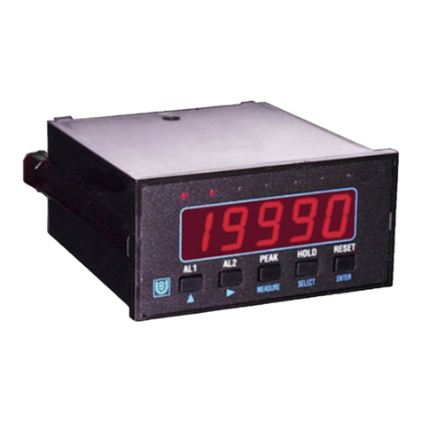
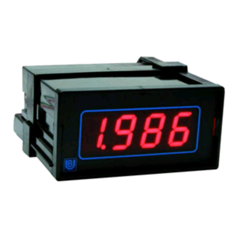
Binding Union METER 44 User manual

Binding Union s.r.l.
STRUMENTI DI MISURA
METER 44
TECHNICAL MANUAL

INDICE / INDEX
CODE DESCRIZIONE DESCRIPTION PAG.
Tutti / All Descrizione generale linea Meter 44 General description Meter 44 line 1
÷
4
4403 Ingresso a richiesta On request input 5
4410
÷
14 Tensione continua Vdc input 6
4433
÷
35 Corrente continua Adc input 6
4421
÷
25 Tensione alternata Vac input 7
4443
÷
45 Corrente alternata Aac input 7
4426
÷
29 Tensione trms V trms 8
4447
÷
49 Corrente trms A trms 8
4461
÷
62 Termocoppie J e K J and K thermocouples 9
4468 Termoresistenze PT100 PT100 thermoresistances 10
4470 Resistenza Resistance 11
4480 Segnali di processo Process signal 12
÷
13
4482 Potenziometro Potentiometer 14
4484 Cella di carico Strain gauge 15
÷
16
4485 Frequenza / velocità Frequency / rate 17
÷
18
Opt21
÷
23 Soglie di allarme Set-point controller 19
÷
20
Opt 25
÷
27 Uscite analogiche Analog outputs 21

Technical Manual (MTU44xx.doc6)
BINDING UNION srl - via Cuorgnè, 21 - 10156 Torino - Italy - Tel. +39 - 011 - 2625414 - Fax +39 - 011 - 2625428 - E-mail binding@binding.it
www.binding.it
1
METER 44
USO DEL MANUALE MANUAL USAGE
La linea METER 44, completamente modulare, è
costituita da una base comune e da una serie di moduli
specifici per ogni tipo di ingresso e per ogni eventuale
opzione. Di conseguenza anche il manuale segue la
stessa impostazione: le prime quattro pagine
riguardano le caratteristiche e le informazioni comuni a
tutta la linea, le pagine successive (pag. 5 e seguenti)
riguardano in modo specifico gli ingressi e le opzioni.
Meter 44 is a modular instrument that includes a
common mainframe with some input modules for
specific applications. As a consequence, the
instrument’s manual follows a modular approach in
which the first four pages deal with general
specifications and the following pages concern the
specific characteristics of the input modules and
options (page 5 and following) .
CARATTERISTICHE SPECIFICATIONS
Punti di lettura : ±1999 digit
Polarità : automatica solo segno meno
Visualizzazione : 3.5 digits LED rossi da 14.2 mm
Stabilità termica : 70 ppm (typ.) 90 ppm (max)
Aggiornamento letture : 2.5 /sec.
Punti decimali : programmabili da frontale
Indicazione fuori scala : pos “1 “ neg “-1 “
Connessioni elettriche : a vite, sez. max 2.5 mm2
Protezione frontale : IP40 (IP65 con acces. AV0316)
Temperatura di impiego : +5...+40° C
Tempo di riscaldamento : 10 minuti
Peso : 350 grammi
Categoria d’installazione : (cat. di sovratensioni) II
Grado inquinamento : 2 (CEI EN61010-1)
•Altre caratteristiche sono indicate alle pagine
specifiche dei vari modelli.
Reading points :
±
1999 digits
Polarity : automatic only minus sign
Display : 3.5 digits, 14.2 mm red LED
Tempco : 70 ppm (typ.) 90 ppm (max)
Reading update : 2.5 /sec
Decimal points : programmable by front side
Display Overrange : pos. “1 “ neg. “-1 “
Connection : screw, max section 2.5 mm2
Front protection : IP40 (IP65 with AV0316 accessory)
Operating temperature : +5...+40° C
Warm-up time : 10 minutes
Weight : 350 grams
Installation category : (overvoltage category) II
Pollution degree : 2 (CEI EN61010-1)
•Other characteristics are indicated in the single
model datasheets.
ALIMENTAZIONE POWER SUPPLY
Alimentazione standard (S) : 90...270Vac 50...60Hz
Potenza assorbita : ≤4VA
Isolamento galvanico : ≥2300 Vac
Resistenza d’isolamento : ≥100 MΩ
Alimentazione opzionale (R) : 10...30 Vac 50...60 Hz
Potenza assorbita : ≤4VA
Corrente di spunto : ≤1.5A
Rigidità dielettrica : ≥500 Vac
Resistenza di isolamento : ≥100MΩ
Alimentazione opzionale (H) : 10....40 Vdc
Potenza assorbita : ≤3 W
Corrente di spunto : ≤1.5A
Rigidità dielettrica : ≥500 Vac
Resistenza di isolamento : ≥100MΩ
Standard power supply (S) : 90...270Vac 50...60Hz
Power :
≤
4VA
Dielectrical strength :
≥
2300 Vac
Insulation resistance :
≥
100 MΩ
Optional power supply (R) :10...30 Vac 50...60 Hz
Power :
≤
4VA
Inrush current :
≤
1.5A
Dielectrical strength :
≥
500 Vac
Isolation resistance :
≥
100MΩ
Optional power supply (H) : 10....40 Vdc
Power :
≤
3 W
Inrush current :
≤
1.5A
Dielectrical strength :
≥
500 Vac
Isolation resistance :
≥
100MΩ

Technical Manual (MTU44xx.doc6)
BINDING UNION srl - via Cuorgnè, 21 - 10156 Torino - Italy - Tel. +39 - 011 - 2625414 - Fax +39 - 011 - 2625428 - E-mail binding@binding.it
www.binding.it
2
METER 44
CODIFICA CODIFICATION
Ogni indicatore riporta sulla sua etichetta il codice
numerico dello strumento che identifica il tipo
d’ingresso e la portata, una lettera che identifica
l’alimentazione e una serie di numeri riferiti alle opzioni
presenti.
Nella tabella che segue sono descritte le opzioni e la
pagina alla quale riferirsi per le informazioni d’uso
(quando necessarie).
Each indicator has on its label the numeric code of the
instrument, which specifies the kind of input and the
range, a letter which specifies the power supply and a
sequence of number related to the possible options.
In the following chart are listed all the available options
and the relevant page where are described the usage
information (when necessary).
Code DESCRIZIONE DESCRIPTION pag.
00 Nessuna None - - -
10 Programmazione diversa dal default Programmation (different from default) - - -
11 Esecuzione neutra Neutral executions - - -
12 Esecuzione personalizzata Custom design - - -
13 Unità ingegneristica non standard Non standard engineering unit - - -
19 Diminuzione aggiornamento lettura (1/sec.) Reduction of reading update rate (1/sec.) - - -
20 Aumento aggiornamento lettura (12.5/sec) Increase of reading update rate (12.5/sec.) - - -
21/22/23 Uscite di allarme a relè Relay set-point controller
25/26/27 Uscite analogiche Analog output
48 Zero fisso Dummy zero 4
49 Blocco della lettura Hold function 4
82 Alimentazione 15Vdc per sensori (mod.4485) 15Vdc auxiliary power supply (4485 model) - - -
90 Estensione della garanzia a 5 anni 5 years warranty extension - - -
91 Trattamento di tropicalizzazione Tropicalization treatment 4
95 Certificato di conformità Conformity certificate - - -
96 Certificato SIT SIT certificate - - -
99 Certificato di calibrazione Binding Union Binding Union calibration certificate - - -
MONTAGGIO DELLO STRUMENTO INSTRUMENT MOUNTING
L’indicatore, in contenitore DIN 48x96, è realizzato per
il montaggio ad incasso a pannello. Praticare quindi un
foro, con le dimensioni indicate in figura 1, nel luogo
d’installazione. L’indicatore viene inserito dalla parte
frontale togliendo i cursori (B) che poi, riposizionati
come in origine, serviranno per bloccare l’indicatore sul
pannello.
Evitare di collocare la parte posteriore dello strumento
in luoghi soggetti ad alta umidità o sporcizia.
Lo strumento è concepito per utilizzo in ambiente
industriale e presenta un’ottima resistenza ai disturbi, è
comunque buona norma installarlo il più lontano
possibile da fonti che possano generare disturbi
elettromagnetici, come motori, elettrovalvole, teleruttori,
ecc.
•Spessore del pannello 1...8 mm
This instrument is conceived for panel mounting (DIN
case sized 48x96). After making a hole in the place of
installation (see fig. 1), insert the instrument by front
taking care to remove the sliders (B) that can be used
to hold the indicator on the panel.
Do not place the back side of the instrument in damp or
dirty places.
The instrument is conceived to be used in industrial
environment and, even if it has a high degree of
resistance, it is advisable to keep it away from sources
of electromagnetic pollution, such as engines,
electrovalves, contactors an so on.
•Panel thickness 1...8 mm
Fig. 1
R2
92-.1
+.5 45-.1
+.5
A
107 mm D
B
C
5mm
1...8 mm

Technical Manual (MTU44xx.doc6)
BINDING UNION srl - via Cuorgnè, 21 - 10156 Torino - Italy - Tel. +39 - 011 - 2625414 - Fax +39 - 011 - 2625428 - E-mail binding@binding.it
www.binding.it
3
METER 44
COLLEGAMENTI ELETTRICI ELECTRICAL CONNECTION
Controllare che la tensione di alimentazione sia
compresa nei valori ammessi dallo strumento.
Gli indicatori dispongono di protezioni sia sugli ingressi
di alimentazione che su quelli di misura, si consiglia
comunque di inserire protezioni (fusibili) adeguate alle
correnti circolanti.
Si raccomanda di separare i cavi del segnale da tutti i
cavi di potenza e di alimentazione per evitare eventuali
disturbi condotti.
La figura 2 indica i collegamenti comuni a tutta la linea
Meter 44.
La morsettiera (C)raccoglie tutti i collegamenti dello
strumento base, per alcune opzioni sarà aggiunto un
connettore superiore la cui descrizione sarà presente
nella pagina specifica dell’opzione.
•Ai 4 morsetti contrassegnati dalla dicitura INPUT
va applicato il segnale da misurare. La loro funzione è
illustrata nella pagina specifica del modulo d’ingresso
alla voce INGRESSI.
•L’alimentazione alternata (codici S-R) si collega ai
morsetti 11 (GND), 12 (L), 13 (N). L’alimentazione
continua (codici H-W-Y) si collega ai morsetti 11
(GND), 12 (+), 13 (-).
N.B. Lo strumento utilizza un alimentatore switching ad
alta frequenza.
Al fine di garantire i livelli di disturbo previsti dalle attuali
norme CE relative alla compatibilità elettromagnetica, si
raccomanda di collegare il morsetto di massa dello
strumento (11) ad una efficace presa di terra.
•Il display test (l. test) consiste nell’accensione
simultanea di tutti i segmenti del display. Tale funzione
si ottiene cortocircuitando i morsetti 6 e 8.
•Molti modelli della linea meter 44 dispongono di
un’alimentazione ausiliaria per l’alimentazione dei
sensori ad essi collegati. Tale alimentazione viene
descritta nelle pagine specifiche dei vari modelli.
Check out if the supply voltage is included in the
ranges allowed for the instrument. The instrument is
provided of protections both on supply and measure
inputs. However, it is advisable to use fuses properly
adequate to the circulating currents. Furthermore, the
input signal wire must be kept separate from line
voltage cables.
Fig. 2 shows the common connections for Meter 44
line.
The terminal board (C) houses all the connections of
the standard instrument; for some options there is a
further upper connector, whose characteristics are
explained in the specific page of the option.
•INPUT 4 terminal boards are those to be connected
to the signal to be measured. Their functions are
explained in the specific manual of the input module,
q.v. INPUT.
•Alternate supply (S-R codes) should be
connected to clamps 11 (GND), 12(L), 13 (N). Direct
supply (H-W-Y codes) should be connected to clamps
11 (GND), 12(+), 13(-).
NOTICE: The instrument is powered by a high
frequency switching power supply.
To guarantee the EMC requirements of European
Standard CE, we recommend to connect the instrument
ground terminal (11) to an effective earth.
•Display test (l. test) consists of the simultaneous
lighting of all display segments. This function is
available short circuiting together clamps 6 and 8.
•For many models of the line meter 44 is available
an auxiliary supply for the sensors eventually
connected. This supply is descibed in the specific
pages related to the various models.
Fig. 2
PROGRAMMING
1234 13
POWER
756 8 1291011
V.out(-)
V.out(+)
N
L
GND
INPUT -+
analog
out
hold
l. test

Technical Manual (MTU44xx.doc6)
BINDING UNION srl - via Cuorgnè, 21 - 10156 Torino - Italy - Tel. +39 - 011 - 2625414 - Fax +39 - 011 - 2625428 - E-mail binding@binding.it
www.binding.it
4
METER 44
PUNTO DECIMALE DECIMAL POINT
L’accensione del punto decimale si ottiene portando in
ON la posizione desiderata del dip-switch SW (Fig. 3)
raggiungibile dopo aver rimosso il filtro ottico (A)
(Fig.1). Tale operazione si rende utile su quei modelli
che prevedono la possibilità di cambiare scala o di
configurare la lettura.
Decimal point is set switching on the desired position of
the SW dip switch (Fig. 3), reachable after removing
the shade filter (A) (Fig. 1). This operation is useful for
those model where it is possible to adjust reading or to
change range.
ZERO FISSO DUMMY ZERO
L’opzione 48 (zero fisso), se presente, ha funzione di
moltiplicatore x 10. Nel caso in cui cessi la necessità di
tale opzione, è possibile disattivarla portando in OFF la
posizione 4 del dip-switch SW (Fig. 3) raggiungibile
dopo aver rimosso il filtro ottico (A) (Fig.1).
Option 48 (Dummy zero) has the function of x10
multiplier. If this function is not needed, switch off the
fourth position of SW dip-switch (Fig. 3)(see above).
BLOCCO DELLA LETTURA HOLD
L’opzione 49 (hold), se presente, blocca sul display
l’ultima lettura effettuata prima che vengano
cortocircuitati i morsetti 7 e 6.
Option 49 holds last reading displayed simply
shortcircuiting pins 7 and 6.
TRATTAMENTO DI TROPICALIZZAZIONE TROPICALIZATION TREATMENT
L’opzione 91 consiste in un trattamento dell’indicatore
con vernici apposite per aumentare la resistenza dei
circuiti alle condizioni ambientali critiche.
Resistente ad una vasta gamma di solventi, lubrificanti,
liquidi di raffreddamento, alla formazione di muffe,
all’esposizione prolungata al caldo dei tropici ed ai
vapori d’acqua salata.
Option 91 is a treatment with a particular paint which
increases the circuits’ resistance and enable the
instrument to bear harsh environmental conditions.
It is resistant against a wide range of solvents, greases,
coolants, moulds, against prolonged exposure to
tropical temperature and salty water steams.
Fig. 3
96 mm
48
113
E
SW
Dp1 Dp2 Dummy
Zero
Dp3
PULIZIA CLEANING
Per pulire il frontale si consiglia l’utilizzo di un panno
morbido inumidito.
Non utilizzare detergenti abrasivi o contenenti solventi.
To clean front side it is advisable to use a soft dampy
cloth. Do not use abrasive or aggressive cleaning
substances.
GARANZIA WARRANTY
L’indicatore è garantito da difetti di materiale o di
costruzione rilevati entro un anno dalla data di acquisto.
Un utilizzo improprio del prodotto o una sua
manomissione comportano il decadimento della
garanzia.
L’eventuale strumento da riparare deve essere inviato,
in porto franco, alla Binding Union con le indicazioni del
difetto riscontrato per agevolare le operazioni di
riparazione.
The instrument is guaranteed against material or
construction defects for one year after purchase.
Improper use of the instrument or evident tampering
cause decline of warranty.
The instrument should be sent to Binding Union for
eventual repair free of charge with the explanation of
the inconvenience noticed.

Technical Manual (MTU44xx.doc6)
BINDING UNION srl - via Cuorgnè, 21 - 10156 Torino - Italy - Tel. +39 - 011 - 2625414 - Fax +39 - 011 - 2625428 - E-mail binding@binding.it
www.binding.it
5
MODEL 4403 - ON REQUEST input
FUNZIONI FUNCTIONS
Indicatore configurabile per segnali in tensione o
corrente su specifica del Cliente. La lettura può essere
cambiata in campo come indicato alla voce
“CONFIGURAZIONE DELLA LETTURA”.
Configurable reading indicator for voltage or current
signal (specified by customer). Reading can be
changed as indicated in “READING PROGRAMMING”.
CARATTERISTICHE SPECIFICATIONS
Precisione : 0.1% (Fondo Scala)
impedenza d’ingresso : tensione 1MΩ
corrente: dipende dalla portata
Massimo segnale d’ingresso : ≤1kV (tensione)
≤0.2 A (corrente)
Accuracy : 0.1% (Full Scale)
Input impedance : voltage 1MΩ
current: depending on range requested
Maximum input signal : ≤1kV (voltage input)
≤0.2 A (current input)
INGRESSI INPUT
Collegamento ingressi : tensione : 1(+) e 4(-)
corrente : 3(+) e 4(-)
Input connections : voltage : 1(+) and 4(-)
current : 3(+) and 4(-)
1234
mA
V
++
12
ON
S1
56
T2T1
43 78910
T3
T1 = zero
T2 = span
T3 = offset
CONFIGURAZIONE DELLA LETTURA READING PROGRAMMING
Per poter accedere ai dip-switch posteriori e ai trimmer
T1 T2 T3, con i quali si effettua la configurazione della
lettura, togliere il coperchio posteriore (E) (fig. 3 pag.4)
Reading configuration can be performed opening the
back side lid (E) (fig.3 pag.4) operating on the dip-
switches and on T1 T2 T3 trimmers.
1 Alimentare lo strumento come indicato sull’etichetta
dei collegamenti
1Power the instrument according to its power
supply, as indicated in the connections label
2 Raggiungere la stabilità termica (10 min) 2 Wait for the warm-up time (10min)
3 Fornire il segnale di misura 3 Connect the input signal
4 Tarare a zero lo strumento applicando il segnale
minimo (es. 0mA - 0V) e ruotando T1 fino a
visualizzare “000”
4 Adjust the instrument zero applying the minimum
signal input (0mA - 0V) and turn T1 until “000”
value is displayed.
5 Calcolare l’escursione della visualizzazione con la
formula Vmax - Vmin dove :
Vmax = visualizzazione con segnale massimo
Vmin = visualizzazione con segnale minimo
es. 0 ÷35mA = -150 ÷+1200
escursione = 1200 - (-150 ) = 1350 digit .
In base al valore ottenuto selezionare la scala
impostando S1 come segue:
escursioni da 0 a 1900 digit = 5 OFF, 6 ON
escursioni da 1900 a 2400 digit = 5 OFF, 6 OFF
escursioni da 2400 a 4000 digit = 5 ON, 6 OFF
5 Make estimation of the reading excursion with the
formula Vmax - Vmin, where :
Vmax = reading with maximum signal
Vmin = reading with minimum signal
for example 0 ÷35mA = -150 ÷+1200
total excursion = 1200 -(-150) = 1350 digit
Select the scale operating on S1 according to the
value obtained by the previous estimation
excursion 0 ÷1900 = 5 OFF, 6 ON
excursion 1900 ÷2400 = 5 OFF, 6 OFF
excursion 2400 ÷4000 = 5 ON, 6 OFF
6 Se è richiesta un’indicazione diversa da “000” con il
segnale minimo in ingresso, è necessario inserire
un offset.
Se l’indicazione voluta è positiva = 7 OFF, 8 ON
Se l’indicazione voluta è negativa = 7 ON, 8 OFF
Per escursioni dell’offset da 0 a 1250 digit
posizionare 9 OFF 10 ON, per escursioni da 1250 a
2000 digit posizionare 9 ON 10 OFF.
Ruotare il trimmer T3 fino al raggiungimento della
visualizzazione desiderata.
6 If it is requested a reading different from 000 with
the minimum input signal, it is necessary to insert
an offset.
For positive value = 7 OFF, 8 ON
For negative value = 7 ON , 8 OFF
For offset excursion 0 ÷1250 digit = 9 OFF,10 ON
For offset excursion 1250 ÷2000 digit = 9 ON,
10 OFF.
Turn trimmer T3 until the desired reading is
reached.
7 Tarare il fondo scala applicando il segnale massimo
da misurare e ruotando il trimmer T2 fino alla
visualizzazione desiderata.
7 Adjust the full scale applying the maximum signal
and operating on trimmer T2 until the desired
reading is reached.
8 Attendere due minuti e poi ripetere le operazioni 4 e
7 se non è utilizzato l’offset o 6 e 7 se si è
introdotto un offset.
8 Wait for 2 minutes and repeat steps 4 and 7 if the
offset has not been inserted, otherwise repeat
steps 6 and 7.

Technical Manual (MTU44xx.doc6)
BINDING UNION srl - via Cuorgnè, 21 - 10156 Torino - Italy - Tel. +39 - 011 - 2625414 - Fax +39 - 011 - 2625428 - E-mail binding@binding.it
www.binding.it
6
MODEL 4410
÷
14 / 4433
÷
35 - V / A DC input
FUNZIONI FUNCTIONS
Voltmetri per tensione continua:
4410 : ±2 V - 4411 : ±200 mV - 4412 : ±20 V 4413
: ±200 V - 4414 : ±500 V
I modelli 4410 (±2 V) e 4411(±200 mV) dispongono di
ingresso differenziale.
Amperometri per corrente continua:
4433 : ±200 mA - 4434 : ±2 A
4435 : 0...60mV da shunt
DC Voltmeters :
4410 :
±
2 V - 4411:
±
200 mV - 4412 :
±
20 V
4413 :
±
200 V - 4414 :
±
500 V
4410 (
±
2 V) - 4411 (
±
200 mV) models, have a
differential input
DC Amperometers :
4433 :
±
200 mA - 4434 :
±
2 A
4435 : 0...60mV from shunt
CARATTERISTICHE SPECIFICATIONS
Precisione : voltmetri : 0.1% (Fondo Scala)
amperometri : 0.2% (Fondo Scala)
Impedenza di ingresso
voltmetri : ≥1 MΩ
4410 / 4411 : 100 MΩ
amperometri : 1 Ω4433
0.1 Ω4434
100 kΩ4435
Massimo segnale d’ingresso : ≤1kV (tensione)
≤1A (4433)
≤4A (4434)
Accuracy :Voltmeters : 0.1% (Full Scale)
Ammeters : 0.2% (Full Scale)
Input impedance
voltmeters :
≥
1 M
Ω
4410 / 4411 : 100 MΩ
amperometers : 1
Ω
4433
0.1
Ω
4434
100 k
Ω
4435
Max. input signal : ≤1kV (voltage input)
≤1A (4433)
≤4A (4434)
INGRESSI INPUT
tensione : morsetti 1(+) e 4(-)
4410 - 4411 : 2(HI) - 3(LO) - 4(COM)
(se non serve l’ingresso differenziale
cortocircuitare tra di loro gli ingressi LO e
COM)
corrente :morsetti 2(+) e 4(-)
4435 (per shunt) : morsetti 2(+) e 4(-)
voltage : inputs 1(+) and 4(-)
4410 - 4411 : 2(HI) - 3(LO) - 4(COM) (if
differential input function is not needed,
shortcircuit input LO and COM)
current : inputs 2(+) and 4(-)
4435 (for shunt) : inputs 2(+) and 4(-)
+
1234
A
V
++
234
HI LO
-
COM
4410/11
T2T1 T3
12
ON
S1
56
43 78
PROGRAMMAZIONE RAPPORTO SHUNT SHUNT RATIO PROGRAMMING
Il modello Meter 4435 viene fornito predisposto per
lettura da shunt 60A / 60mV (per multipli e sottomultipli,
6A e 600A, spostare solo punto decimale).
Per cambiare il rapporto agire come segue:
togliere il coperchio posteriore (E) (fig.3 pag.4) e
settare in ON una sola delle 8 posizioni del dip-switch
secondo la seguente tabella. Impostare poi il punto
decimale per ottenere la visualizzazione desiderata.
Model Meter 4435 is supplied programmed for reading
from 60A / 60mV shunt (for multiples and submultiples,
6A and 600A, set only decimal point ).
To change shunt ratio remove the instrument back plug
(E) (fig. 3 pag.4) and switch ON one of the eight dip-
switch positions according to the following table.
Set then the decimal point to obtain the desired
reading.
S1 DIP-SWITCH POSITION SHUNT
1 20-200-2000A / 60 mV
2 15-150-1500A / 60 mV
3 10-100-1000A / 60 mV
4 8-80-800A / 60 mV
5 6-60-600A / 60 mV
6 5-50-500A / 60 mV
7 40-400A / 60 mV
8 25-250A / 60 mV

Technical Manual (MTU44xx.doc6)
BINDING UNION srl - via Cuorgnè, 21 - 10156 Torino - Italy - Tel. +39 - 011 - 2625414 - Fax +39 - 011 - 2625428 - E-mail binding@binding.it
www.binding.it
7
MODEL 4421
÷
25 / 4443
÷
45 - V / A AC input
FUNZIONI FUNCTIONS
Voltmetri per tensioni alternate :
4421 : 0...2 V - 4422 : 0...20 V - 4423 : 0...200 V
4424 : 0...500 V
4425 : TV/100Vac (TV /100√3 a richiesta)
Amperometri per correnti alternate :
4443 : 0...200 mA - 4444 : 0...2 A
4445 : 0...5 A TA/5
AC Voltmeters :
4421 : 0...2 V - 4422 : 0....20V - 4423 : 0....200V
4424 : 0....500V
4425 : VT/100Vac (VT /100√3 if requested)
AC Amperometers :
4443 : 0...200 mA - 4444 : 0...2 A
4445 : 0...5 A CT/5
CARATTERISTICHE SPECIFICATIONS
Impedenza di ingresso
voltmetri : ≥1MΩ
amperometri : 4443 : 1Ω
4444 : 0.1Ω
4445 : 0.01Ω
Precisione (F = 40...400 Hz)
voltmetri : ±0.2 % (Fondo Scala)
amperometri : ±0.5 % (Fondo Scala)
Massimo segnale d’ingresso
voltmetri : ≤1kV
amperometri : 4443 : ≤1A
4444 : ≤4A
4445 : ≤10A
Input impedance
voltmeters :
≥
1M
Ω
amperometers : 4443 : 1
Ω
4444 : 0.1
Ω
4445 : 0.01
Ω
Accuracy (F = 40....400 Hz)
voltmeters :
±
0.2 % (Full Scale)
amperometers :
±
0.5 % (Full Scale)
Maximum input voltage
voltmeters :
≤
1kV
amperometers : 4443 :
≤
1A
4444 :
≤
4A
4445 :
≤
10A
INGRESSI INPUT
Collegamento ingressi
tensione : morsetti 1(Fase) e 4 (neutro)
corrente : morsetti 2(In) e 4(return) per 4443 e 4444
morsetti 3(In) e 4(return) per 4445
Input connections
voltage : inputs 1(phase) and 4(neutral)
current : inputs 2(In) and 4(return) for 4443 and 4444
inputs 3(In) and 4(return) for 4445
1234
A
V
34
4445
T2T1 T3
12
ON
S1
56
43 78
PROGRAMMAZIONE RAPPORTO DEL TA CT RATIO PROGRAMMING
Il modello Meter 4445 viene fornito predisposto per
lettura diretta 5Aac o tramite TA 5/5Aac (per multipli,
50A e 500A, spostare solo punto decimale).
Per cambiare il rapporto togliere il coperchio posteriore
(E) (fig.3 pag.4) e settare in ON una sola delle 8
posizioni del dip-switch secondo la seguente tabella.
Impostare poi il punto decimale per ottenere la
visualizzazione desiderata.
Il modello Meter 4425 viene fornito settato per TV
1000/100Vac. Per cambiare il rapporto togliere il
coperchio posteriore (E) (Fig. 3) e settare in ON una
sola delle 8 posizioni del dip-switch secondo la
seguente tabella. Impostare poi il punto decimale per
ottenere la visualizzazione desiderata.
Model Meter 4445 is supplied programmed for 5Aac
direct reading or for 5/5Aac current transformers (for
multiples, 50A and 500A, set only decimal point )..
To change CT ratio remove the back plug (E) (fig.3
pag.4) and switch ON one of the eight dip-switch
positions according to the following table.
Then set the decimal point to obtain the desired
reading.
Meter 4425 is supplied adjusted for voltage transformer
1000/100Vac. To change VT ratio, remove the back
plug (E) (fig.3) and set one of 8 dip-switch positions
according to the following table. Then set decimal point
to obtain the desired reading.
S1 DIP-SWITCH POSITION VT (4425) CT (4445)
1 100-1000V / 100 Vac 20-200-2000A / 5Aac
2 800V / 100 Vac 15-150-1500A / 5 Aac
3 600V / 100 Vac 10-100-1000A / 5 Aac
4 500V / 100 Vac 8-80-800A / 5 Aac
5 400V / 100 Vac 6-60-600A / 5 Aac
6 380 / 100 Vac 5-50-500A / 5 Aac
7 220 / 100 Vac 40-400A / 5 Aac
8 110 / 100 Vac 25-250A / 5 Aac

Technical Manual (MTU44xx.doc6)
BINDING UNION srl - via Cuorgnè, 21 - 10156 Torino - Italy - Tel. +39 - 011 - 2625414 - Fax +39 - 011 - 2625428 - E-mail binding@binding.it
www.binding.it
8
MODEL 4426
÷
29 / 4447
÷
49 - V / A TRMS input
FUNZIONI FUNCTIONS
Voltmetri per tensioni alternate :
4426 : 0...2 V - 4427 : 0...20 V - 4428 : 0...200 V
4429 : 0...500 V
Amperometri per correnti alternate :
4447 : 0...200 mA - 4448 : 0...2 A
4449 : 0...5 A TA/5
AC Voltmeters :
4426 : 0...2 V - 4427 : 0...20 V - 4428 : 0...200 V
4429 : 0...500 V
AC Amperometers :
4447 : 0...200 mA - 4448 : 0...2 A
4449 : 0...5 A CT/5
CARATTERISTICHE SPECIFICATIONS
Impedenza di ingresso
voltmetri : ≥1MΩ
amperometri : 4447 : 1Ω
4448 : 0.1Ω
4449 : 0.01Ω
Precisione
voltmetri : ±0.2 % (F.S.) F = 20...2000 Hz (Sin.)
±1% (F.S.) DC + AC Crest Factor ≤6
amperometri : ±0.5 % (F.S.) F = 20...2000 Hz (Sin.)
±1% (F.S.) DC + AC Crest Factor ≤6
Massimo segnale d’ingresso
voltmetri : ≤1kV
amperometri : 4447 : ≤1A
4448 : ≤4A
4449 : ≤10A
Tempo di risposta : 200 mS
N.B. Per tutti i dati non indicati rimane valida la tabella
generale di pagina 1.
Input impedance
voltmeters :
≥
1M
Ω
amperometers : 4447 : 1
Ω
4448 : 0.1
Ω
4449 : 0.01
Ω
Accuracy
voltmeters :
±
0.2 % (F.S.) F = 20...2000 Hz (Sine)
±
1% (F.S.) DC + AC Crest Factor
≤
6
amperometers:
±
0.5 % (F.S.) F = 20...2000 Hz (Sine)
±
1% (F.S.) DC + AC Crest Factor
≤
6
Maximum input voltage
voltmeters :
≤
1kV
amperometers : 4447 :
≤
1A
4448 :
≤
4A
4449 :
≤
10A
Response Time : 200 mS
N.B. For all other data, refer to the general table on
page 1.
INGRESSI INPUT
Collegamento ingressi
tensione : morsetti 1(Fase) e 4(Neutro)
corrente : morsetti 2(In) e 4(Return) per 4447 e 4448
morsetti 3(In) e 4(Return) per 4449
Input connections
voltage : inputs 1(Phase) and 4(Neutral)
current : inputs 2(In) and 4(Return) for 4447 and 4448
inputs 3(In) and 4(Return) for 4449
1234
A
V
34
4449
T2T1 T3
12
ON
S1
56
43 78
PROGRAMMAZIONE RAPPORTO DEL TA CT RATIO PROGRAMMING
Il modello Meter 4449 viene fornito predisposto per
lettura diretta 5Aac o tramite TA 5/5Aac (per, 50A e
500A, cambiare solo il punto decimale).
Per cambiare il rapporto togliere il coperchio posteriore
(E) (fig.3 pag.4) e settare in ON una sola delle 8
posizioni del dip-switch secondo la seguente tabella.
Impostare poi il punto decimale per ottenere la
visualizzazione desiderata.
Model Meter 4449 is supplied programmed for 5Aac
direct reading or for 5/5Aac current transformers (for
multiples, 50A and 500A, set only decimal point).
To change CT ratio remove the back plug (E) (fig.3
pag.4) and switch ON one of the eight dip-switch
positions according to the following table.
Then set the decimal point to obtain the desired
reading.
DIP-SWITCH POSITION CT
1 20-200-2000A / 5Aac
2 15-150-1500A / 5 Aac
3 10-100-1000A / 5 Aac
4 80-800A / 5 Aac
5 60-600A / 5 Aac
6 5-50-500A / 5 Aac
7 40-400A / 5 Aac
8 25-250A / 5 Aac

Technical Manual (MTU44xx.doc6)
BINDING UNION srl - via Cuorgnè, 21 - 10156 Torino - Italy - Tel. +39 - 011 - 2625414 - Fax +39 - 011 - 2625428 - E-mail binding@binding.it
www.binding.it
9
MODEL 4461 / 62 - J / K THERMOCOUPLE input
FUNZIONI FUNCTIONS
Indicatore per misura di temperatura da termocoppie J
(Fe-Co) (mod. 4461) o K (Cr-Al) (mod. 4462).
Indicator for temperature measurement from
thermocouples J (Fe-Co)(mod.4461) and K (Cr-Al)
(mod.4462).
CARATTERISTICHE SPECIFICATIONS
Impedenza d’ingresso : ≥1MΩ
Massima tensione d’ingresso : ≤50 Vrms
Precisione : ±0,3% @ 20°C (F.S.)
±1% 0....+50 °C (F.S.)
Campo scala 4461 : 0...500 °C
Campo scala 4462 : 0...1000 °C
Segnalazione ingresso aperto : fondo scala ≥110%
Taratura : secondo tabella IEC 584-1 (ITS90)
Input impedance :
≥
1M
Ω
Maximum input voltage :
≤
50 Vrms
Accuracy :
±
0,3% @ 20°C (Full scale)
±
1% 0....+50 °C (Full scale)
4461 range : 0...500 °C
4462 range : 0...1000 °C
Input break detection : full scale
≥
110%
Calibration : according to IEC 584-1 (ITS90) table
INGRESSI INPUT
Termocoppia J (Fe-Co) : 3 (-) e 4 (+)
Termocoppia K (Cr-Al) : 3 (-) e 4 (+)
J thermocouple (Fe-Co): 3 (-) and 4 (+)
K thermocouple (Cr-Al): 3 (-) and 4 (+)
(+)
34
(-)
T1 T2 T3
12
S1
43 56
T4
PROGRAMMAZIONE PROGRAMMING
Gli indicatori vengono forniti programmati in base al
codice di ordinazione. E’ possibile in ogni caso passare
da un modello all’altro cambiando tipo di termocoppia e
programmazione.
Per cambiare la programmazione togliere il coperchio
posteriore (E) (fig.3 pag.4) e settare il dip-switch S1
secondo la seguente tabella.
Instruments are supplied programmed according to the
ordering code. It is always possible to change from one
model to the other simply changing the kind of
programming and thermocouple.
To program the instrument, remove the back side lid
(E) (fig.3 pag.4) and operate on dip-switch S1
according to the following table:
S1 1 2 3 4 5 6
J (Fe-Co) on off on on on off
K (Cr-Al) off on off off off on
TARATURA CALIBRATION
I trimmer T1...T4 servono per la taratura del modulo.
Tale operazione è effettuata da Binding Union con le
apparecchiature di riferimento; è possibile, tuttavia,
ritoccare la visualizzazione per esigenze particolari.
Per questo intervento è indispensabile l’utilizzo di un
calibratore (adatto per queste applicazioni è il modello
MULTICAL 8310) o di un segnale di riferimento.
Per il modello 4461 (termocoppie J)
T1 : taratura di zero
T2 : taratura di fondo scala.
Per il modello 4462 (termocoppie K)
T3 : taratura di zero
T4 : taratura di fondo scala.
Trimmers T1...T4 are used for instrument calibration.
This operation is performed by Binding Union by means
of a reference calibrator. However, it is possible
to adjust the reading for particular needs.
For this kind of operation it is advisable to use a
calibrator (for example our model MULTICAL 8310) or
a reference signal.
Model 4461 ( J Thermocouple )
T1 : zero adjust
T2 : full scale adjust
Model 4462 ( K Thermocouple )
T3 : zero adjust
T4 : full scale adjust

Technical Manual (MTU44xx.doc6)
BINDING UNION srl - via Cuorgnè, 21 - 10156 Torino - Italy - Tel. +39 - 011 - 2625414 - Fax +39 - 011 - 2625428 - E-mail binding@binding.it
www.binding.it
10
MODEL 4468 - PT100 THERMORESISTANCE input
FUNZIONI FUNCTIONS
Indicatore 3 scale selezionabili per misura di
temperatura da termoresistenze PT 100.
Scala di default -100.0...+199.9 °C
Three scale selectable indicator for PT100
temperature measurements.
Default scale is -100.0...+199.9 °C
CARATTERISTICHE SPECIFICATIONS
Precisione : ±0.5% (Fondo Scala)
Resistenza di linea : 5 Ω
Risoluzione : 1°C (scale -200...+850°C e °F)
0,1°C (scala -100...+200°C)
Taratura : secondo tabella IEC 751 ( ITS90)
Accuracy :
±
0.5% (Full Scale)
Line resistance : 5
Ω
Resolution : 1°C (scale -200...+850°C and °F)
0,1°C (scale -100...+200°C)
Calibration : according to IEC 751 (ITS90) table
INGRESSI INPUT
L’indicatore è studiato per rilevamenti di temperatura da
PT100 a tre fili.
E’ tuttavia possibile utilizzarlo anche con termoresi-
stenze a due fili semplicemente cortocircuitando i
morsetti 3 e 4 e collegando la sonda sui morsetti 1 e 3.
This indicator is conceived for temperature
measurement from 3 wires PT100.
Nevertheless, it is possible to use it also for 2 wire
thermoresistences simply shortcircuiting clamps 3 and
4 and connecting the probe on clamps 1 and 3.
12
RTD
+
34
-
T2T1 ON
S1
1234
T1 = zero T2 = span
SELEZIONE SCALA SCALE SELECTION
Gli indicatori vengono forniti programmati sulla scala
-100.0...+199.9°C, salvo diversamente indicato.
Quando si vuole utilizzare una delle altre scale
disponibili agire come segue:
togliere il coperchio posteriore (E) (fig.3 pag.4) e
settare il dip-switch a 4 vie secondo la seguente
tabella. Quando viene selezionata la scala 850°C o
quella in °F è necessario spegnere il punto decimale, la
descrizione di questa operazione si trova a pagina 3
alla voce punto decimale.
Per eventuali verifiche di taratura in campo si consiglia
l’utilizzo del calibratore portatile Multical 8310.
Indicators are supplied programmed with the range
-100.0...+199.9°C, if not differently specified.
If it is needed another range among the available, act
as follows:
remove the back side lid (E) (fig.3 pag.4) and act on 4
ways dip-switch according to the following chart.
When is selected the range up to 850°C or the °F one,
it is necessary to turn off the decimal point; the
description of how to do it is on page 3.
In order to verify the calibration it is advisable to use
our portable calibrator Multical 8310.
TEMPERATURE SW1 SW2 SW3 SW4
-200 ... +850 °C ON OFF OFF OFF
-100.0... +199.9 °C OFF ON OFF OFF
-328 ... +1562 ° F OFF OFF ON OFF

Technical Manual (MTU44xx.doc6)
BINDING UNION srl - via Cuorgnè, 21 - 10156 Torino - Italy - Tel. +39 - 011 - 2625414 - Fax +39 - 011 - 2625428 - E-mail binding@binding.it
www.binding.it
11
MODEL 4470 - RESISTANCE input
FUNZIONI FUNCTIONS
Indicatore con 4 scale per misura di resistenze.
Lo strumento viene fornito impostato per fondoscala di
2 KΩ.
4 scale indicator for resistance measurement.
Default scale is 2KΩ.
CARATTERISTICHE SPECIFICATIONS
Precisione : ±0.2%
Sorgente corrente : 10µA (200kΩ)...10mA (200Ω)
Impedenza d’ingresso : 100MΩ
Sovratensione massima : ≤50Vrms
Segnalazione ingresso aperto : fondo scala ≥110%
Accuracy : ±0.2%
Current source : 10
µ
A (200k
Ω
)...10mA (200
Ω
)
Input impedance : 100M
Ω
Overvoltage :
≤
50Vrms
Input break detection : Hi-set
≥
110%
INGRESSI INPUT
L’indicatore è studiato per misure di resistenza con
sistema a 4 fili per compensare nel miglior modo
possibile la resistenza di linea.
This indicator is conceived for 4 wires resistance
measurement in order to compensate in the best way
the line resistance.
12
Rx
34
T1 ON
S1
12 T2
34
SELEZIONE DEL FONDOSCALA FULL-SCALE SELECTION
Se si desidera cambiare la portata dell’indicatore,
togliere il coperchio posteriore (E) (fig.3 pag.4) e
settare in ON una sola delle 4 posizioni del dip-switch
S1 secondo la seguente tabella.
Impostare poi il punto decimale per ottenere la
visualizzazione desiderata.
In order to change the range of the indicator, remove
the back side lid (E) (fig.3 pag.4) and set ON oly one of
the 4 position of S1 dip-switch according to the
following chart.
Select then the decimal point to obtain the desided
reading.
S1 DIP-SWITCH POSITION RANGE
1 200
Ω
2 2 K
Ω
3 20 K
Ω
4 200 K
Ω
TARATURA ADJUSTMENT
Per effettuare il controllo periodico in campo della
taratura è consigliato l’utilizzo del calibratore portatile
MULTICAL 8310.
Se viene utilizzata una sola delle 4 scale, è possibile
migliorare la precisione dello strumento fino allo 0.1%,
a patto di disporre di un riferimento con precisione
migliore dello 0.1%.
T1 : taratura zero
T2 : taratura fondoscala.
It is advisable to make periodically a check of the
calibration by means of our MULTICAL 8310.
If it is used a single scale, it is possible to improve the
instrument’s accuracy up to 0.1%, as long as a
reference signal better than 0.1% is available.
T1 : zero adjust
T2 : full scale adjust

Technical Manual (MTU44xx.doc6)
BINDING UNION srl - via Cuorgnè, 21 - 10156 Torino - Italy - Tel. +39 - 011 - 2625414 - Fax +39 - 011 - 2625428 - E-mail binding@binding.it
www.binding.it
12
MODEL 4480 - PROCESS input
FUNZIONI FUNCTIONS
Indicatore per segnali di processo selezionabili tra
4...20 mA 0...20 mA 0...10 V 0...5 V 1...5 V con
lettura configurabile e alimentazione ausiliaria per
sensori. Per selezionare un ingresso diverso da quello
fornito fare riferimento alla voce “SELEZIONE
INGRESSI”, la lettura può essere cambiata in campo
come indicato alla voce “CONFIGURAZIONE DELLA
LETTURA”.
Process signal indicator with selectable input among
4...20 mA 0...20 mA 0...10 V 0...5 V 1...5 V with
configurable reading and sensor power supply.
To select an input different from the default one, refer
to “INPUT SELECTION”, while the reading can be
changed as indicated in “READING PROGRAMMING”.
CARATTERISTICHE SPECIFICATIONS
Precisione : 0.1%
impedenza d’ingresso : tensione 1MΩ
corrente 10Ω
Ingresso di default : 4...20 mA
Massimo segnale d’ingresso : ≤1kV (tensione)
≤0.2 A (corrente)
Alimentazione sensori : 24Vdc 30mA
Accuracy : 0.1%
Input impedance : voltage 1MΩ
current 10Ω
Default input : 4...20 mA
Maximum input signal : ≤1kV (voltage input)
≤0.2 A (current input)
Sensors supply : 24Vdc 30mA
INGRESSI E ALIMENTAZIONE AUSILIARIA INPUT AND AUXILIARY POWER SUPPLY
Collegamento ingressi : tensione : 1(+) e 4(-)
corrente : 3(+) e 4(-)
Alimentazione sensori: 10(+) e 9(-) (vedi fig.2 pag.3)
L’indicatore può essere usato con ingresso passivo con
o senza alimentazione del sensore oppure con
ingresso attivo in tecnica due fili.
La massa dell’alimentazione ausiliaria non è isolata
dalla massa del segnale, nel caso di sensori che
richiedano isolamento inserire un isolatore esterno o
usare un’alimentazione separata.
Input connections : voltage : 1(+) and 4(-)
current : 3(+) and 4(-)
Sensors supply : 10(+) and 9(-) (see fig.2 page 3)
This indicator may be used both with passive input
(with or without sensor supply) or with 2 wire active
input.
The auxiliary power supply earth is not isolated from
the signal earth. If the sensor requires a specific
isolation, insert an external isolator or use a separate
power supply.
1234
mA
V
++
COLLEGAMENTO IN TECNICA DUE FILI /
TWO WIRES CONNECTION
RET(-)
1999
Instrument
4480
103
bar
IN(+)
Transducer
3
1
2
SELEZIONE INGRESSI INPUT SELECTION
Lo strumento viene fornito programmato per segnali in
corrente, se si desidera visualizzare un segnale diverso
da quello di default, togliere il coperchio posteriore (E)
(fig.3 pag.4) e agire sulle prime 4 posizioni del dip-
switch S1 seguendo la tabella sottostante:
Instrument’s default setting is current ; for a different
reading it is necessary to remove the back side lid (E)
(fig.3 pag.4) and operate on the first 4 positions of S1
dip-switch according to the following table:
DIP-SWITCH S1 4...20mA 0...20mA 0...10V 0...5V 1...5V
1 ON ON OFF OFF OFF
2 ON OFF ON OFF ON
3 ON OFF OFF OFF ON
4 ON OFF OFF OFF ON

Technical Manual (MTU44xx.doc6)
BINDING UNION srl - via Cuorgnè, 21 - 10156 Torino - Italy - Tel. +39 - 011 - 2625414 - Fax +39 - 011 - 2625428 - E-mail binding@binding.it
www.binding.it
13
MODEL 4480 - PROCESS input
CONFIGURAZIONE DELLA LETTURA READING PROGRAMMING
Sul modello Meter 4480 la configurazione della lettura
si effettua tramite i dip-switch posteriori (già visti per
selezionare gli ingressi) e i trimmer T1, T2 e T3.
Per la verifica o la taratura in campo si consiglia l’uso
del Multical 8310 che genera i segnali campione in mA
e V (oltre a molti altri) con una precisione dello 0.1%.
Meter 4480 reading configuration can be performed
using the back dip-switch (as per input selection) and
T1, T2 and T3 trimmers.
To check or calibrate on field, it is advisable to use our
MULTICAL 8310, which generates sample signals both
mA and V (among others) with an accuracy of 0.1%.
12
ON
S1
56
T2T1
43 78910
T3
T1 = zero
T2 = span
T3 = offset
1 Alimentare lo strumento come indicato sull’etichetta
dei collegamenti
1Power on the instrument according to the
connections label
2 Raggiungere la stabilità termica (10 min)
2 Wait for the warm-up time
3 Fornire il segnale di misura (se si utilizza il
MULTICAL 8310, collegare i due cavetti rosso e
nero ai morsetti 3(+) e 4(-) per segnali in corrente o
1(+) e 4(-) per segnali in tensione)
3 Connect the input signal (if MULTICAL 8310 is
used, connect the red and the black wires to
clamps 3(+) and 4(-) for current signals or to
clamps 1(+) and 4(-) for voltage signals)
4 Tarare a zero lo strumento applicando il segnale
minimo (es. 4mA - 0V) e ruotando T1 fino a
visualizzare “000”
4 Adjust the instrument zero giving the input
minimum signal (4mA - 0V) and turning T1 until
“000” is displayed
5 Calcolare l’escursione della visualizzazione con la
formula Vmax - Vmin dove :
Vmax = visualizzazione con segnale massimo
Vmin = visualizzazione con segnale minimo
es. 4 ÷20mA = -150 ÷+1200
escursione = 1200 - (-150 ) = 1350 digit .
In base al valore ottenuto selezionare la scala
impostando S1 come segue:
escursioni da 0 a 1900 digit = 5 OFF, 6 ON
escursioni da 1900 a 2400 digit = 5 OFF, 6 OFF
escursioni da 2400 a 4000 digit = 5 ON, 6 OFF
5 Calculate the reading excursion with the formula
Vmax - Vmin, where :
Vmax = reading with maximum signal
Vmin = reading with minimum signal
for example 4 ÷20mA = -150 ÷+1200
total excursion = 1200 -(-150) = 1350 digit
Select the full scale operating on S1 according to
the value obtained by the previeous estimation
excursion 0 ÷1900 = 5 OFF, 6 ON
excursion 1900 ÷2400 = 5 OFF, 6 OFF
excursion 2400 ÷4000 = 5 ON, 6 OFF
6 Se è richiesta un’indicazione diversa da “000” con il
segnale minimo in ingresso, è necessario inserire un
offset.
Se l’indicazione voluta è positiva = 7 OFF, 8 ON
Se l’indicazione voluta è negativa = 7 ON, 8 OFF
Per escursioni dell’offset da 0 a 1250 digit
posizionare 9 OFF e 10 ON, per escursioni da 1250
a 2000 digit posizionare 9 ON 10 OFF.
Ruotare il trimmer T3 fino al raggiungimento della
visualizzazione desiderata.
6 If it’s needed a different reading from 000 with the
minimum input signal, it is necessary to insert an
offset.
For positive offset = 7 OFF, 8 ON
For negative offset = 7 ON , 8 OFF
For offset excursion 0 ÷1250 digit = 9 OFF,10 ON
For offset excursion 1250 ÷2000 digit = 9 ON,
10 OFF.
Turn trimmer T3 until the desired reading is
reached.
7 Tarare il fondo scala applicando il segnale massimo
da misurare e ruotando il trimmer T2 fino alla
visualizzazione desiderata.
7 Adjust the full scale applying the maximum signal
and operate on trimmer T2 until the desired reading
is reached.
8 Attendere due minuti e poi ripetere le operazioni 4 e
7 se non è stato utilizzato l’offset o 6 e 7 se si è
introdotto un offset.
8 Wait for 2 minutes and repeat steps 4 and 7 if the
offset has not been used, repeat steps 6 and 7 in
presence of an offset.

Technical Manual (MTU44xx.doc6)
BINDING UNION srl - via Cuorgnè, 21 - 10156 Torino - Italy - Tel. +39 - 011 - 2625414 - Fax +39 - 011 - 2625428 - E-mail binding@binding.it
www.binding.it
14
MODEL 4482 - POTENTIOMETER input
FUNZIONI FUNCTIONS
Indicatore con lettura configurabile in campo per
abbinamento a potenziometri lineari.
Configurable reading indicator for linear potentiometer.
CARATTERISTICHE SPECIFICATIONS
Precisione : 0.1%
impedenza d’ingresso : 1010 Ω(typ.)
Alimentazione potenziometro: 5V ±4% (10 mA max)
Valore potenziometro : 500 Ω...50 kΩ
Accuracy : 0.1%
Input impedance : 1010 Ω(typ.)
Potentiometer power supply:5V ±4% (10 mA max)
Potentiometer value : 500 Ω...50 kΩ
VISTA POSTERIORE / BACK SIDE COLLEGAMENTI / CONNECTIONS
12
ON
S1
56
T2T1
43 7 8 9 10
T3
12 34
+V IN COM
CONFIGURAZIONE DELLA LETTURA READING PROGRAMMING
Per cambiare la lettura dello strumento, togliere il
coperchio posteriore (E) (fig.3 pag.4) ed agire sui dip-
switch posteriori e i trimmer T1 T2 T3 come indicato.
To change reading, remove the back side lid (E) (fig.3
pag.4) and operate on the dip-switch and T1 T2 T3
trimmers.
1 Collegare il potenziometro come da disegno e
alimentare lo strumento come indicato
sull’etichetta dei collegamenti.
1Connect potentiometer and power-up the
instrument according to its power supply.
2 Raggiungere la stabilità termica (10 min).
2 Wait for its warm-up (10 min).
3 Tarare a zero lo strumento, portando il
potenziometro al minimo della sua corsa, e
ruotando T1 fino a visualizzare “000”
3 Adjust the instrument zero by setting the
potentiometer at minimum value of its run and
rotating T1 until the zero is reached
4 Calcolare l’escursione della visualizzazione con la
formula Vmax - Vmin dove :
Vmax = visualizzazione con segnale massimo
Vmin = visualizzazione con segnale minimo
es. visualizzazione = -150 ÷+1200
escursione = 1200 - (-150 ) = 1350 digit .
In base al valore ottenuto selezionare la scala
impostando S1 come segue:
escursioni da 0 a 1900 digit = 5 OFF, 6 ON
escursioni da 1900 a 2400 digit = 5 OFF, 6 OFF
escursioni da 2400 a 4000 digit = 5 ON, 6 OFF
4 Make estimation of the reading through the
formula Vmax - Vmin where :
Vmax = reading with maximum signal
Vmin = reading with minimum signal
for example reading = -150 ÷+1200
total excursion = 1200 -(-150) = 1350 digit
Select the full scale by operating S1 according to
the value obtained by the previews estimation
excursion 0 ÷1900 = 5 OFF, 6 ON
excursion 1900 ÷2400 = 5 OFF, 6 OFF
excursion 2400 ÷4000 = 5 ON, 6 OFF
5 Se è richiesta un’indicazione diversa da “000” con
il segnale minimo in ingresso, è necessario
inserire un offset.
Se l’indicazione voluta è positiva = 7 OFF, 8 ON
Se l’indicazione voluta è negativa = 7 ON, 8 OFF
Per escursioni dell’offset da 0 a 1250 digit
posizionare 9 OFF 10 ON, per escursioni da 1250
a 2000 digit posizionare 9 ON 10 OFF.
Ruotare il trimmer T3 fino al raggiungimento della
visualizzazione desiderata.
5 If a reading different from 000 with the minimum
input signal is needed, it is necessary to put an
offset.
For positive offset = 7 OFF, 8 ON
For negative offset = 7 ON , 8 OFF
For offset excursion 0 ÷1250 digit = 9 OFF,10
ON. For offset excursion 1250 ÷2000 digit = 9
ON, 10 OFF.
Rotate trimmer T3 until the desired reading is
reached.
6 Tarare il fondo scala portando il potenziometro al
massimo della sua corsa e ruotando il trimmer T2
fino alla visualizzazione desiderata.
6 Adjust the full scale by applying the maximum
signal and by operating trimmer T2 until the
desired reading is obtained.
7 Attendere due minuti e poi ripetere le operazioni 3
e 6 se non è utilizzato l’offset o 5 e 6 se si è
introdotto un offset.
7 Wait for 2 minutes and repeat steps 3 and 6 if the
offset has not been used, repeat steps 5 and 6 in
case of used offset.

Technical Manual (MTU44xx.doc6)
BINDING UNION srl - via Cuorgnè, 21 - 10156 Torino - Italy - Tel. +39 - 011 - 2625414 - Fax +39 - 011 - 2625428 - E-mail binding@binding.it
www.binding.it
15
MODEL 4484 - STRAIN GAUGE input
FUNZIONI FUNCTIONS
Indicatore con lettura configurabile per la misura di
peso, forza e deformazioni, tramite celle di carico.
Configurable reading indicator for strain gauge.
CARATTERISTICHE E COLLEGAMENTI SPECIFICATIONS AND CONNECTIONS
Precisione : 0.1% (Fondo Scala)
Collegamento ingressi :
ingresso alto : morsetto 1
ingresso basso : morsetto 2
alimentazione cella Vexc. + : morsetto 3
alimentazione cella Vexc. - : morsetto 4
Tensione di eccitazione : 10V±4% (35mA max)
Circuito di ingresso : differenziale ad alta impedenza
CMRR (dc - 60 Hz) @ G=10 : 106dB typ.
Sensibilità di ingresso : 1/2/3mV/V selezionabile
Tensione massima di ingresso : ±5V
Corrente di polarizzazione : 15nA (typ)
Impedenza di ingresso : 1010 Ω(typ)
Banda passante @ -3dB : 5kHz
Carico minimo : 280Ω
Accuracy : 0.1% (Full Scale)
Input connections :
input High : terminal 1
input Low : terminal 2
excitation voltage + : terminal 3
excitation voltage - : terminal 4
Excitation voltage : 10V±4% (35mA max)
Input circuit : high impedance differential
CMRR (dc - 60 Hz) @ G=10 : 106dB (typ)
Input sensitivity : 1/2/3mV/V selectable
Maximum input voltage : ±5V
Bias current : 15 nA (typ)
Input impedance : 1010
Ω
(typ)
Bandwidth @ -3dB : 5kHz
Minimum load : 280
Ω
PROGRAMMAZIONE PROGRAMMING
Nel modello Meter 4484 è necessario togliere il tappo
posteriore (E) (fig.3 pag.4) e selezionare la sensibilità
della cella di carico agendo sui dip-switch:
On model Meter 4484 remove the instrument back plug
(E) (fig.3 pag.4) and select cell sensitivity by dip-switch:
SENSITIVITY S1 S2 S3
1mV / V OFF ON ON
2mV / V ON OFF ON
3mV / V ON ON OFF
La taratura può essere effettuata in due modi:
a) Se si intende utilizzare un segnale di riferimento,
cortocircuitare i morsetti 2 e 4 e collegarli al negativo
del calibratore, collegare il positivo al morsetto 1 del
4484. Con segnale d’ingresso nullo ruotare T1 fino a far
visualizzare 0 allo strumento. Con segnale
corrispondente al fondo scala della cella ruotare T2 fino
a far visualizzare la portata della cella.
b) Se si intende effettuare la taratura in campo,
collegare la cella di carico e aggiustare lo zero dello
strumento con il trimmer T1. Per il fondo scala si
possono utilizzare due metodi:
-utilizzando un peso campione posizionato sulla cella e
ruotando T2 fino al raggiungimento della
visualizzazione corrispondente al peso.
-utilizzando la resistenza di calibrazione che può
essere interna alla cella (cella a sei fili) o quella interna
allo strumento (da 100 kΩ) e risolvendo le formule:
Configuration may be performed in two ways:
a) If you like to use a reference signal, put terminal
boards 2 and 4 in short circuit and connect them to the
negative lead of the calibrator, connect then the
positive lead to the terminal board 1 of 4484. When
input signal is zero, turn T1 until the 0 is reached.
Apply the signal corresponding to cell full scale and
operating trimmer T2 until cell full scale reading is
obtained.
b) Connect strain gauge and adjust the zero with T1
trimmer. For full scale adjust, you can use two
methods:
- by using a “sample weight” on strain gauge, turn T2
until the reading corresponding to weight is reached.
- by using calibration resistance, which can be inside
the strain gauge (6 wires cell) or that in the instrument
(100 K
Ω
), and solving the following formulas.
Rx = (Rp ×100000) ÷(Rp + 100000) Vout = 10 ×[ Rp ÷(Rp + Rx) ] -0.5Lett. = Fs ×Vout ÷Vo
dove:
Rp = resistenza del ponte
Vo = sensibilità cella ×tensione di alimentazione
Vexc (espresso in Volt)
Fs = indicazione dello strumento (espressa in digit)
riferita alla portata della cella (es 100.0 Kg = 1000)
Lett. = valore da far visualizzare allo strumento con
resistenza di calibrazione inserita (cella scarica).
where:
Rp = cell resistance
Vo = cell sensitivity ×voltage power cell Vexc
( expressed in Volt)
Fs = meter indication (expressed in digit) referred to
cell capacity (ex. 100.0 Kg = 1000)
Lett = meter indication with push-button (unloaded
cell).

Technical Manual (MTU44xx.doc6)
BINDING UNION srl - via Cuorgnè, 21 - 10156 Torino - Italy - Tel. +39 - 011 - 2625414 - Fax +39 - 011 - 2625428 - E-mail binding@binding.it
www.binding.it
16
MODEL 4484 - STRAIN GAUGE input
Premere poi il pulsante che mette in parallelo ad un
ramo della cella la resistenza di calibrazione e ruotare
T2 per far visualizzare allo strumento il numero
ottenuto.
TARA - Per rendere attiva la funzione di tara portare in
OFF la posizione 4 di S1.
Con la cella di carico inserita ed in condizione di TARA
regolare il trimmer T3 fino a leggere 000 sul display.
Push button that put the calibration resistance on the
strain gauge arm and turn T2 to obtain a reading
corresponding to the obtained number.
TARE - To activate tare function, set position 4 of S1
to OFF.
When strain gauge is inserted and you are in tare mode
turn T3 trimmer till you read 000 on display.
T1
S1
T2 T3 123 4
T1 = Zero Adj. T2 = Span Adj. T3 = Tare
COLLEGAMENTO CELLA 4 FILI FOUR WIRE CONNECTION
2
3
1Sig HI
Sig LO
(+)Exc
(-)Exc
4
9
10
COLLEGAMENTO CELLA 6 FILI SIX WIRE CONNECTION
CAL 10
4
9
(-)Exc
2
3
1Sig HI
Sig LO
(+)Exc

Technical Manual (MTU44xx.doc6)
BINDING UNION srl - via Cuorgnè, 21 - 10156 Torino - Italy - Tel. +39 - 011 - 2625414 - Fax +39 - 011 - 2625428 - E-mail binding@binding.it
www.binding.it
17
MODEL 4485 - FREQUENCY / RATE input
FUNZIONI FUNCTIONS
Indicatore 4 scale selezionabili per misura di frequenza
da rete o di velocità da sensori tipo NPN e PNP.
Four scale selectable frequency meter for line or
NPN and PNP sensor measurement.
CARATTERISTICHE SPECIFICATIONS
Campo di frequenza : 0...20 / 200 / 2000 / 20000 Hz
Precisione : 0.2% (Fondo Scala)
Sensibilità ingressi
Tensione alternata : 12...250 Vrms
TTL/CMOS : 0...5 V ( soglia a 2,5V)
Pick-up : 0...5 V ( soglia a 0,5Vp)
Proximity : 0,5...10 Vpp
Impedenza ingresso
Tensione alternata : ≥490 KΩ
Sonda ottica/Open collector/Proximity : ≥10 KΩ
CMOS/TTL/Pick-up : ≥100 KΩ
Sovraccarico
Tensione alternata : ≤1 KVrms
TTL/CMOS/Proximity/Pick-up : ≤50 Vdc
Alimentazione sensori
morsetti 3(+) e 4(-) : +5 Vdc 30 mA
: +15 Vdc 30 mA (opz. 82)
N.B. Per tutti i dati non indicati rimane valida la tabella
generale di pagina 1
Frequency range : 0...20 / 200 / 2000 / 20000 Hz
Accuracy : 0.2% (Full Scale)
Input sensitivity
Alternating voltage : 12...250 Vrms
TTL/CMOS : 0...5 V (2.5 V threshold)
Pick-up : 0...5 V (0.5 Vp threshold)
Proximity : 0.5...10 Vpp
Input impedance
Alternating voltage :
≥
490 K
Ω
Sonda ottica/Open collector/Proximity :
≥
10 K
Ω
CMOS/TTL/Pick-up :
≥
100 K
Ω
Overload
Alternating voltage :
≤
1 KVrms
TTL/CMOS/Proximity/Pick-up :
≤
50 Vdc
Sensor power supply
terminals 3(+) and 4(-) : +5 Vdc 30 mA
: +15 Vdc 30 mA (opt. 82)
N.B. For not specified data, please refer to general
table on page 1.
COLLEGAMENTO INGRESSI INPUT CONNECTIONS
Tensione alternata : morsetti 1 (Hi) / 4 (Lo)
TTL / CMOS / Proximity
Pick-up / Open collector / PNP : morsetti 2 (Hi) / 4 (Lo)
Encoder / Sonda ottica : morsetti 2(Hi)/ 3(aux +)/ 4(Lo)
Alternating voltage : terminals 1(Hi) / 4(Lo)
TTL / CMOS / Proximity
Pick-up / Open collector / PNP : terminals 2(Hi) / 4(Lo)
Encoder / Optical probe : terminals 2(Hi)/ 3(aux)/ 4(Lo)
2234
HI AUX(+)
Sonda ottica
Encoder
Proximity
Pick-up
GND
4
SELEZIONE SCALA SCALE SELECTION
La scala di default è 200 Hz. Per cambiare il fondo
scala è necessario rimuovere il tappo posteriore (E)
(fig.3 pag.4) e agire sul dip-switch S1 come indicato:
-Per fondo scala 20 Hz : 4-6-7-8-9-10 ON
-Per fondo scala 200 Hz : 3-6-7 ON
-Per fondo scala 2000 Hz : 2-4 ON
-Per fondo scala 20000 Hz : 1 ON
Default scale is 200 Hz. Full scale can be modified by
removing the back plug (E) (fig.3 pag.4) and operating
the dip-switch S1 as follows :
-20 Hz full scale : 4-6-7-8-9-10 ON
-200 Hz full scale : 3-6-7 ON
-2000 Hz full scale : 2-4 ON
-20000 Hz full scale : 1 ON

Technical Manual (MTU44xx.doc6)
BINDING UNION srl - via Cuorgnè, 21 - 10156 Torino - Italy - Tel. +39 - 011 - 2625414 - Fax +39 - 011 - 2625428 - E-mail binding@binding.it
www.binding.it
18
MODEL 4485 - FREQUENCY / RATE input
SELEZIONE SENSORE SENSOR SELECTION
Lo strumento viene fornito con configurazione standard
per ricevere segnali da Proximity, Sonde Ottiche,
sensori Open Collector. E’ possibile tuttavia
predisporre il tachimetro in campo (se non richiesto in
sede d’ordine) per l’utilizzo con segnali diversi.
Estrarre lo strumento dal contenitore e programmare,
sul modulo orizzontale, il dip-switch S3 a due posizioni
come segue:
segnali da pick-up : posizione 1 OFF e pos. 2 ON
segnali TTL / Encoder / PNP : posizione 1 e 2 OFF
tensione di rete : posizione 1 e 2 OFF
config. standard : posizione 1 ON e pos. 2 OFF
N.B. Quando lo strumento è fuori dal proprio
contenitore non deve essere alimentato.
Instrument is suitable to receive signals from
Proximity, Optical probes, Open Collector sensors.
It is possible to set the tachometer to use it with
different signals.
Remove case instrument; operate the horizontal
module dip-switch S3 as follows:
pick-up signals : position 1 OFF, pos. 2 ON
TTL signals / Encoder / PNP : position 1 and 2 OFF
alternating voltage : position 1 and 2 OFF
default condition : position 1 ON, pos.2 OFF
N.B. When the instrument is out of its case, it must not
be powered.
CONFIGURAZIONE DELLA LETTURA READING PROGRAMMING
Per permettere a Meter 4485 di leggere il numero di giri
o un qualunque altro valore diverso dalla frequenza
d’ingresso agire come segue.
Risolvere la seguente formula per trovare il valore Nda
impostare sul dip-switch S1 del modulo d’ingresso:
N = visualizzazione x 10 : Fmax
dove N = ΣNx
Fmax = frequenza massima
Nx = 1 / 2 / 4 / 8 / 16 / 32 / 64 / 128 / 256 / 512
S1 = 1 / 2 / 3 / 4 / 5 / 6 / 7 / 8 / 9 / 10
Con tutti gli switches ON si ottiene N = 1023
Con tutti gli switches OFF si ottiene N = 0
Esempio : frequenza massima Fmax = 800 Hz
visualizzazione = 1600
N = 1600 x 10 : 800 N = 16000 : 800 = 20
S1-3 ON S1-5 ON
Nel caso il numero da impostare abbia dei decimali si
può approssimare per eccesso o per difetto, oppure è
possibile programmare il dip-switch S2 a 4 posizioni
sapendo che:
la posizione 3 vale 0.25
la posizione 4 vale 0.5
On model Meter 4485, full scale frequency and display
is programmed by using Dip-switch S1 of the input
module according to the following formula :
N = read x 10 : Fmax
where N =
Σ
Nx
Fmax = max frequency
N1 = 1 / 2 / 4 / 8 / 16 / 32 / 64 / 128 / 256 / 512
S1 = 1 / 2 / 3 / 4 / 5 / 6 / 7 / 8 / 9 / 10
With all switches ON N = 1023
With all switches OFF N = 0
Example : full scale frequency Fmax = 800 Hz
read = 1600
N = 1600 x 10 : 800 N = 16000 : 800 = 20
S1-3 ON S1-5 ON
If the number to be set has decimals, you can
approximate it to the nearest whole number , or it is
possible to program dip-switch S2 knowing that:
position 3 is equal to 0.25
position 4 is equal to 0.5
UTILIZZO PER BASSE FREQUENZE LOW FREQUENCY USAGE
Se lo strumento è utilizzato per visualizzare frequenze
più basse di 10 Hz è consigliabile l’inserimento di un
ritardo utilizzando il dip-switch S2 4 vie:
pos. 1 in ON = ritardo 1 sec.
pos. 2 in ON = ritardo 10 sec.
If instrument is used to display frequencies lower than
10 Hz, it is advisable to insert a delay by using dip-
switch 4 positions S2:
pos. 1 ON = delay 1 sec.
pos. 2 ON = delay 10 sec.
12
ON
S1
56
43 78910
ON
S2
1234
T2
T1
Table of contents
Other Binding Union Measuring Instrument manuals
