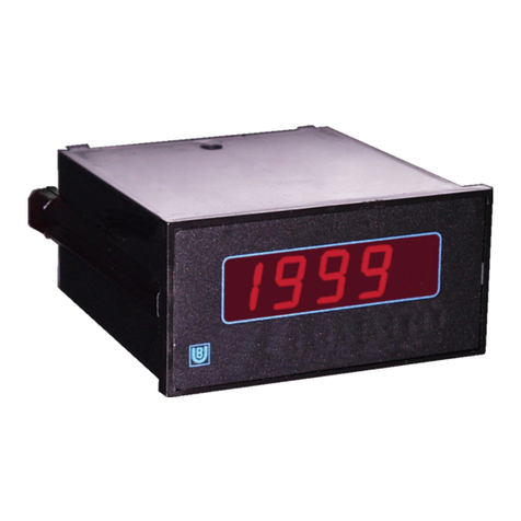
Binding Union FAST 3485 User manual

Technical Manual (MTU3485.doc28)
BINDING UNION srl - via Cuorgnè, 21 - 10156 Torino - Italy - Tel. +39 - 011 - 2625414 - Fax +39 - 011 - 2625428 - E-mail binding@binding.it
www.binding.it
1
FAST 3485 - FREQUENCY / RATE input
V
AL
Il modello FAST 3485 è un frequenzimetro / tachimetro
studiato per il controllo delle frequenze di rete e per il
rilevamento del numero di giri tramite sensori.
The model FAST 3485 is a Frequency meter /
Tachometer conceived for the network frequency
control and for the detection of revolution number , by
mean of sensors.
CARATTERISTICHE SPECIFICATIONS
Punti di lettura : ±1999 digit
Polarità : automatica solo segno meno
Visualizzazione : 3.5 digit LED rossi da 14.2 mm
Stabilità termica : 100 ppm (typ.) 150 ppm (max)
Aggiornamento letture : 2.5 /sec.
Punti decimali : programmabili da frontale
Indicazione fuori scala : pos “1 “ neg “-1 “
Connessioni elettriche : a vite, sez. max 2.5 mm2
Temperatura di impiego : 0...+50° C
Tempo di riscaldamento : < 15 minuti primi
Contenitore : DIN 43700, in policarbonato nero
Dimensioni : 36x72x81 mm
Peso : 200 grammi
Categoria d’installazione : (cat. di sovratensioni) II°
Grado inquinamento : 2 (CEI EN61010-1)
Reading points :
±
1999 digits
Polarity : automatic only minus sign.
Display : 3.5 digits, 14.2 mm red LED’s
Tempco : 100 ppm (typ.) 1500 ppm (max)
Reading update : 2.5 /sec
Decimal points : programmable by front-end
Display Overrange : pos. “1 “ neg. “-1 “
Connection : screw, max section 2.5 mm2
Operating temperature : 0...+50° C
Warm-up time : < 15 minutes
Case : DIN 43700 black polycarbonate
Dimensions : 36x72x81 mm
Weight : 200 grams
Installation category : (overvoltage category) II°
Pollution degree : 2 (CEI EN61010-1)
IDENTIFICAZIONE DEL MODELLO MODEL IDENTIFICATION
Code INSTRUMENTS Range Accuracy Input Impedance Protection
3485 Frequency meter - tachometer 0...20.00kHz
4 ranges
0.3% 1
≥
490 k
Ω
2
≥
10 k
Ω
1 kV ac input
50 Vdc sensor input
Code POWER Code OPTIONS Code OPTIONS
A Standard 230Vac 00 None 31 1 relay set-point controller
B Optional 115Vac 10 Programmation 91 Tropicalisation Treatment
C Optional 24Vac 11 Neutral executions 95 Conformity certificate
H Optional 10...40Vdc 12 Custom design 99 Binding Union calibration certificate
13 non standard engineering unit

Technical Manual (MTU3485.doc28)
BINDING UNION srl - via Cuorgnè, 21 - 10156 Torino - Italy - Tel. +39 - 011 - 2625414 - Fax +39 - 011 - 2625428 - E-mail binding@binding.it
www.binding.it
2
FAST 3485 - FREQUENCY / RATE input
MONTAGGIO DELLO STRUMENTO INSTRUMENT MOUNTING
Dopo la preparazione di un foro nel luogo
d’installazione, l’indicatore viene inserito dalla parte
frontale togliendo i cursori (B) che poi riposizionati
come in origine serviranno per bloccare l’indicatore sul
pannello. Spessore del pannello 1...4 mm
Make a hole in the place of installation, insert the
instrument by front, taking care of removing the sliders
(B) that will hold in place the indicator on the panel.
Panel thickness 1...4 mm
4mm(max)
576
32.5
+.2
-.0
+.2
-.0
69.0
B
DP1 DP2 DP3
Decimal point
selection
1
2
3
ALIMENTAZIONI POWER SUPPLY
Alimentazione standard (A) : 230 Vac 50...60Hz
Potenza assorbita : ≤4VA
Isolamento galvanico : ≥2300 Vac 50 Hz
Resistenza d’isolamento : ≥100 MΩ500 Vdc
Alimentazione opzionale (B) : 115 Vac 50...60 Hz
Potenza assorbita : ≤4VA
Rigidità dielettrica : ≥1500 Vac 50 Hz
Resistenza di isolamento : ≥100MΩ- 500 Vdc
Alimentazione opzionale (C) : 24 Vac 50...60 Hz
Potenza assorbita : ≤4 VA
Rigidità dielettrica : ≥500 Vac 50 Hz
Resistenza di isolamento : ≥100MΩ500Vdc
Alimentazione opzionale (H) : +10....40 Vdc
Potenza assorbita : ≤5 W
Rigidità dielettrica : ≥500 Vac 50 Hz
Resistenza di isolamento : ≥100MΩ500Vdc
Standard power supply (A) : 230 Vac 50...60Hz
Power :
≤
4VA
Dielectrical strength :
≥
2300 Vac 50 Hz
Insulation resistance :
≥
100 MΩ500Vdc
Optional power supply (B) :115 Vac 50...60 Hz
Power :
≤
4VA
Dielectrical strength :
≥
1500 Vac 50 Hz
Insulation resistance :
≥
100 MΩ500Vdc
Optional power supply (C) : 24 Vac 50...60 Hz
Power :
≤
4 VA
Dielectrical strength :
≥
500 Vac 50 Hz
Isolation resistance :
≥
100MΩ500 Vdc
Optional power supply (H) : +10...40 Vdc
Power :
≤
5 W
Dielectrical strength :
≥
500 Vac 50 Hz
Isolation resistance :
≥
100MΩ500 Vdc
CONNESSIONE DI TERRA GROUNDING
Al fine di garantire i livelli di disturbo previsti dalle attuali
norme CE relative alla compatibilità elettromagnetica, si
raccomanda di collegare il morsetto di massa dello
strumento (8) ad una efficace presa di terra.
To guarantee the EMC requirements of European
Standard CE , we recommend to connect the
instrument ground terminal (8) to an effective earth.
PUNTO DECIMALE DECIMAL POINT
L’accensione del punto decimale (DP1 DP2 DP3) si
ottiene agendo sui pin jumpers presenti sul pannello
frontale dello strumento ed accessibili rimuovendo il
filtro ottico.
Decimal point (DP1 DP2 DP3) can be selected by
operating the pin jumpers available on the instrument
front end beyond the red filter

Technical Manual (MTU3485.doc28)
BINDING UNION srl - via Cuorgnè, 21 - 10156 Torino - Italy - Tel. +39 - 011 - 2625414 - Fax +39 - 011 - 2625428 - E-mail binding@binding.it
www.binding.it
3
FAST 3485 - FREQUENCY / RATE input
COLLEGAMENTI CONNECTIONS
Collegamento ingressi
Tensione alternata : morsetti 4 (Hi) / 7 (Lo)
TTL / CMOS / Proximity
Pick-up / Open collector / PNP : morsetti 5 (Hi) / 7 (Lo)
Encoder / Sonda ottica : morsetti 5(Hi)/ 6(aux +)/ 7(Lo)
Alimentazione: 9 (+) e 10 (-) morsetto 8 GND
Collegamenti allarme
i morsetti 1, 2 e 3 sono i contatti del relè dell’allarme,
sono abilitati solo se presente l’opzione 31
Input connections
Alternating voltage : terminals 4(Hi) / 7(Lo)
TTL / CMOS / Proximity
Pick-up / Open collector / PNP : terminals 5(Hi) / 7(Lo)
Encoder / Optical probe : terminals 5(Hi)/ 6(aux)/ 7(Lo)
Power Supply: 9 (+) 10 (-) and 8 GND
Set-point connections
inputs 1, 2, and 3 are relay contacts, they are operating
only if present option 31
GND
POWER N (-)
L (+)
1234 756 8910
INPUT
OPT 31
COM NA NC
5
Proximity
Pick-up
7
567
HI AUX(+)
Optical probe
Encoder
GND
CARATTERISTICHE INGRESSO INPUT SPECIFICATIONS
Campo di frequenza : 0...19.99 / 199.9 / 1999 Hz
19.99 kHz
Sensibilità ingressi
Tensione alternata : 12...250 Vrms
TTL/CMOS : 0...5 V ( soglia a 2,5V)
Pick-up : 0...5 V ( soglia a 0,5Vp)
Proximity : 0,5...10 Vpp
Impedenza ingresso
Tensione alternata : ≥490 KΩ
Sonda ottica/Open collector/Proximity : ≥10 KΩ
CMOS/TTL/Pick-up : ≥100 KΩ
Sovraccarico
Tensione alternata : ≤1 KVrms
TTL/CMOS/Proximity/Pick-up : ≤50 Vdc
Alimentazione sensori
morsetti 6(+) e 7(-) : +5 Vdc 30 mA
N.B. Per tutti i dati non indicati rimane valida la tabella
generale di pagina 1
Frequency range : 0...19.99 / 199.9 / 1999 Hz
19.99 kHz
Input sensitivity
Alternating voltage : 12...250 Vrms
TTL/CMOS : 0...5 V (2.5 V threshold)
Pick-up : 0...5 V (0.5 Vp threshold)
Proximity : 0.5...10 Vpp
Input impedance
Alternating voltage :
≥
490 K
Ω
Sonda ottica/Open collector/Proximity :
≥
10 K
Ω
CMOS/TTL/Pick-up :
≥
100 K
Ω
Overload
Alternating voltage :
≤
1 KVrms
TTL/CMOS/Proximity/Pick-up :
≤
50 Vdc
Sensor power supply
terminals 6(+) and 7(-) : +5 Vdc 30 mA
N.B. For not specified data, please refer to general
table on page 1.
SELEZIONE SCALA SCALE SELECTION
La scala di default è 199.9 Hz. Se usato come
frequenzimetro, per cambiare il fondo scala è
necessario impostare il ponticello S2 come indicato:
-Per fondo scala 19.99 Hz : 4-6-7-8-9-10 ON
-Per fondo scala 199.9 Hz : 3-6-7 ON
-Per fondo scala 1999 Hz : 2-4 ON
-Per fondo scala 19.99 kHz : 1 ON
Default scale is 199.9 Hz. Full scale can be modified by
operating the jumper S2 as follows :
-19.99 Hz full scale : 4-6-7-8-9-10 ON
-199.9 Hz full scale : 3-6-7 ON
-1999 Hz full scale : 2-4 ON
-19.99 kHz full scale : 1 ON
SELEZIONE SENSORE SENSOR SELECTION
Lo strumento viene fornito con configurazione standard
per ricevere segnali da Proximity, Sonde Ottiche,
sensori Open Collector, NPN. E’ possibile tuttavia
predisporre il tachimetro in campo (se non richiesto in
sede d’ordine) per l’utilizzo con segnali diversi.
Programmare, i ponticelli S1 come segue:
segnali da pick-up : posizione 1 OFF e pos. 2 ON
segnali TTL / Encoder / PNP : posizione 1 e 2 OFF
tensione di rete : posizione 1 e 2 OFF
config. standard : posizione 1 ON e pos. 2 OFF
ON= ponticello inserito - OFF= ponticello disinserito
Instrument is delivered in default configuration to
receive signals from Proximity, Optical probes, Open
Collector sensors, NPN. It is anyway possible to
program even on field the tachometer to accept
different signals.
Set S1 jumpers as follows:
pick-up signals : position 1 OFF, pos. 2 ON
TTL signals / Encoder / PNP : position 1 and 2 OFF
alternating voltage : position 1 and 2 OFF
default condition : position 1 ON, pos.2 OFF
ON = Jumper inserted - OFF = jumper not inserted

Technical Manual (MTU3485.doc28)
BINDING UNION srl - via Cuorgnè, 21 - 10156 Torino - Italy - Tel. +39 - 011 - 2625414 - Fax +39 - 011 - 2625428 - E-mail binding@binding.it
www.binding.it
4
FAST 3485 - FREQUENCY / RATE input
CONFIGURAZIONE DELLA LETTURA READING PROGRAMMING
Nella funzione tachimetro la programmazione della
frequenza di ingresso e della lettura si effettua
impostando sul ponticello S2 il valore Ncalcolato con la
seguente formula:
N = visualizzazione x 10 : Fmax
dove N = ΣNx
Fmax = frequenza massima
If model FAST 3485 is used as a tachometer, full scale
frequency and display is programmed by setting on
Jumper S2 , the value N , calculated according to the
following formula :
N = reading x 10 : Fmax
where N =
Σ
Nx
Fmax = max frequency
S2 1 2 3 4 5 6 7 8 9 10
Nx 1 2 4 8 16 32 64 128 256 512
Con tutti i ponticelli ON si ottiene N = 1023
Con tutti i ponticelli OFF si ottiene N = 0
(ON = ponticello inserito)
Esempio : frequenza massima Fmax = 800 Hz
visualizzazione = 1600
N = 1600 x 10 : 800 N = 16000 : 800 = 20
S2 = 3 - 5 ON
La visualizzazione di zero e fondo scala può essere
aggiustata con i trimmer T1 e T2
With all jumpers ON N = 1023
With all jumpers OFF N = 0
(ON = Jumper inserted)
For example : full scale frequency Fmax = 800 Hz
read = 1600
N = 1600 x 10 : 800 N = 16000 : 800 = 20
S2 = 3 - 5 ON
Zero and full scale display can be adjusted operating
T1 and T2 trimmers.
UTILIZZO PER BASSE FREQUENZE LOW FREQUENCY USAGE
Se lo strumento è utilizzato per visualizzare frequenze
più basse di 10 Hz è consigliabile l’inserimento di un
ritardo utilizzando il ponticello S1 a 4 vie:
pos. 3 in ON = ritardo 1 sec.
pos. 4 in ON = ritardo 10 sec.
If instrument is used to display frequencies lower than
10 Hz, it is advisable to insert a delay by using 4
positions jumper S1:
pos. 3 ON = delay 1 sec.
pos. 4 ON = delay 10 sec.
T1
110
S1
14
T2
S2
110
ADEGUAMENTO AL N° CILINDRI MOTORE CYLINDERS NUMBER ADJUST
(TERMINALE 1 BOBINA) la frequenza degli impulsi
generati dai contatti del ruttore dipenderà ovviamente
dal n° dei cilindri. La frequenza (f) ed il numero di giri
del motore (n) potranno essere calcolati in base al
numero dei cilindri (C), applicando le seguenti formule:
f = n x C / 120 n = 120 x f / C
Per esempio per un motore a 4 cilindri e 3000 giri al
minuto, il calcolo darà il seguente risultato :
f = 3000 x 4 / 120 = 100 Hz
Per avere la visualizzazione di 3000 (300x10) giri al
minuto impostare su S2 N=30 2 - 3 - 4 - 5 = ON
(vedi par. CONFIGURAZIONE DELLA LETTURA)
(TERMINAL 1 IGNITION COIL) The pulse frequency
produced by the contactor of the ignition coil depends
on the cylinders number. The frequency (f) and the
engine turns number (n) as a function of the cylinders
number (C) can be determined according to the
following relations:
f = n x C / 120 n = 120 x f / C
As an example for a four cylinder engine with 3000rpm,
the result is the following:
f = 3000 x 4 / 120 = 100Hz
To obtain the display of 3000 (300x10) rpm/min
set on S2 N= 30 2 - 3 - 4 - 5 = ON
(see at READING PROGRAMMING)
RELAZIONE PER ALTERNATORE ALTERNATOR ADJUST
Per i segnali prelevati dal terminale W dell’alternatore
calcolare la frequenza con la formula:
For signal coming from the W terminal of the alternator
use the following relation:
Hz = 60
P
2x R x n
Dove:
P = poli dell’alternatore
R = diametro puleggia motore diviso diametro puleggia
alternatore
n = numero di giri dal motore
Where:
P = alternators poles number
R = ratio of the motor and the alternator wheels
n = engine turns number

Technical Manual (MTU3485.doc28)
BINDING UNION srl - via Cuorgnè, 21 - 10156 Torino - Italy - Tel. +39 - 011 - 2625414 - Fax +39 - 011 - 2625428 - E-mail binding@binding.it
www.binding.it
5
SET-POINT CONTROLLER - OPTION 31
Questa opzione permette di segnalare il superamento
di un limite predeterminato dall’utilizzatore.
La segnalazione avviene sia tramite un LED visibile sul
frontale dello strumento sia tramite la commutazione di
un relè di potenza i cui contatti sono disponibili in
morsettiera.
[1] pulsante visualizzazione punto d’intervento - [2]
LED segnalazione condizione di allarme - [3] trimmer
impostazione punto d’intervento - [4] ponticello
impostazione intervento di minima o di massima.
This option shows the exceeding of a pre-set threshold
adjustable by the user.
The alarm warning operates both a visible LED on the
instrument front panel and a power relay whose
contacts are available on the instrument terminal board.
[1] set-point display switch - [2] alarm condition
warning LED - [3] set-point trimmer - [4] jumper for
minimum or maximum set-point adjustment
[1]
[2]
[3]
[4]
[T2]
[K1]
0
2
4
DP1 DP2 DP3
Decimal point
selection
1
2
3
[1]
[2]
[3]
[4]
1
2
3
FUNZIONI FUNCTIONS
La scheda allarme (opzione 31) consente di
controllare il segnale visualizzato dallo strumento nel
quale viene inserita.
L’allarme può essere impostato di massima o di
minima, nel primo caso si avrà la commutazione
quando il segnale sarà più alto del set-point, nel
secondo la commutazione avverrà quando il segnale
sarà più basso del set-point.
La condizione di allarme cessa automaticamente
quando il segnale misurato torna ai valori ottimali.
Per visualizzare il punto d’intervento dell’allarme è
sufficiente premere il pulsante [1] (senza togliere il filtro
frontale) con un oggetto appuntito (penna a sfera)
Alarm controller board (option 31) allows control of the
signal displayed by the instrument where it is inserted.
The alarm can have maximum or minimum set-points:
in the first case the alarm becomes active when the
measured signal exceeds a given value (maximum
operating), in the second case the switching will
happen when the signal falls below a given value.
Alarm condition automatically ends when measured
signal returns to correct value.
To display alarm set-point, push button [1] (without
removing front filter) with a pointed objet (like a pen).
CARATTERISTICHE SPECIFICATIONS
Precisione d’intervento: 0.3%
Isteresi : entro 5 digit
Ripetibilità intervento : ±1digit
Ritardo d’intervento : 0.2...4 sec
Impostazione punto intervento: 0...+1999
tramite trimmer frontale
Portata contatti Relè : 1A 250V (50VA max)
Segnalazione allarme : led rosso frontale
Intervention accuracy : 0.3%
Hysteresys : within 5 digit
Repeatibility :
±
1digit
Switching delay : 0.2...4 sec.
Set-point programming : 0...+1999 by front panel
trimmer
Relays : 1A 250V (50VA max)
Warning : by front panel red led
PROGRAMMAZIONE PROGRAMMING
L’ opzione 31 viene fornita impostata come allarme di
massima con ritardo di circa 0.2 sec. Per impostare il
punto d’intervento (set-point) togliere il filtro ottico
frontale dello strumento, premere il pulsante [1] e
ruotare il trimmer [3] fino al raggiungimento del valore
desiderato. Per impostare l’intervento di minima
spostare il ponticello [4] dalla posizione 2-3 alla
posizione 1-2. Per variare il tempo del ritardo
d’intervento, togliere il filtro ottico frontale dello
strumento, svitare la vite di fissaggio, togliere la
morsettiera estraibile e sfilare lo strumento spingendo
dalla morsettiera. Ruotare T2 in senso orario per
aumentare il ritardo d’intervento.
Option 31 is supplied as a maximum set-point and with
0.2 sec delay time. To adjust set-point, remove front
red panel, push switch [1]; turn trimmer [3] till desired
value is displayed. To set-up minimum set-point, move
jumper [4] from 2-3 to 1-2 position.
To change delay time, remove front red panel, unscrew
the locking screw and remove extractable connector,
take off instrument from his case.
Turn clockwise trimmer T2 to increase delay time.
Table of contents
Other Binding Union Measuring Instrument manuals
