Binsfeld TorqueTrak Revolution User manual

TorqueTrak Revolution
Torque and Power
Monitoring System
User’s Guide
866001-9_J

- 1 -
Table of Contents
System Overview 2
System Components 3
Controls and Connections Overview 4
Controls and Connections 5
Power Input 5
Torque Output Signal 6
Torque Signal Calibration Controls 7
Power Output Signal 10
Power Signal Calibration Controls 11
Speed (RPM) and Direction Output Signals 14
System Status Indicator Lights 16
Transmitter Status Indicator Light 17
Installation Procedure 18
Set Up Procedure 21
Appendix A: Revolution Specifications 25
Appendix B: Torque Calibration Calculations 27
Appendix C: Error Codes & Troubleshooting 29
Appendix D: Strain Gage Application 32
Warranty and Service Information 37

- 2 -
System Overview
The TorqueTrak Revolution is a single channel, non-contact,
inductively-powered system designed to provide continuous
torque, speed (rpm), power, and direction of rotation data from a
rotating shaft. The system consists of two primary components:
the Rotating Shaft Collar with integral Transmitter Module and
the Master Control Unit with stationary Power Ring.
The TorqueTrak Revolution features:
➢four simultaneous data signals: torque, speed, power
and direction
➢user adjustable scaling for torque and shaft power
➢digital design inherently immune to electrical noise
➢non-contact inductive power and data transfer eliminates
wear surface for long life without signal degradation
➢does not require shaft modification or machine
disassembly to install
➢fully encapsulated rotating electronics with status
indicator light on the transmitter
➢switchable low pass filter
➢remote shunt system calibration
➢self diagnosis with error mode indicator lights
➢offset and gain settings stored in non-volatile memory
➢high resolution data (14 bit)
The TorqueTrak Revolution is a rugged precision instrument
designed for applications where ongoing measurement of torque
and/or power on a rotating shaft is required.
- 3 -
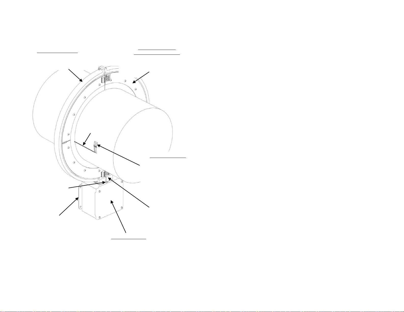
System Components
Figure 1 –Revolution System Components
Strain Gage Sensor
(Glued to shaft; not
included but ordered as
an accessory)
Converts mechanical
torque to electrical signal
which is transmitted from
the Rotating Collar to the
Stationary Power Ring.
Stationary Power Ring
Sends power to the Rotating
Collar and receives data signal
from the Rotating Collar
Rotating Shaft Collar
(with Transmitter Module)
Clamps to shaft with bolts provided.
Houses Transmitter Module which
converts strain gage signal to digital
code.
Master Control Unit
Provides power signal to Power Ring.
Processes digital data signal from
transmitter to produce four 4-20mA output
signals corresponding to torque, speed
(RPM), shaft power and direction of
rotation.
Mounting Flange
Lead wires from
collar for sensor
connection
(shaft)
Mounting Block with
speed sensor
Main System
Status Indicator
Light

- 4 -
Controls and Connections Overview
Power Config Switches
1 = Pos FS power
2 = Neg FS power
1&2 = Zero power
3 = Set zero power to 4mA
4 = Reverse signal polarity
5 = Power once/revolution
6 = ON for <10 RPM
7 = Off Off On On
8 = Off On Off On
Filter: 1000 12 1.5 0.1Hz
Note: When Torque
Configuration Switches 1
and 2 are ON
simultaneously, the system
simulates a zero input
signal from the transmitter
(nominally generates a 12
mA output).
Torque Config Switches
1 = Pos FS torque
2 = Neg FS torque
1&2 = Zero torque
3 = Set zero torque to 4mA
4 = Reverse signal polarity
5 = Bypass user calibration
6 = Not used.
7 = Off Off On On
8 = Off On Off On
Filter: 1000 12 1.5 0.1Hz
System Calibration
“EN” to enable
Offset/Gain switches.
“SAVE” to store.
Gain (Scale)
Adjustment
System Status Indicators
Stator: ON = Input power level okay
Rotor: ON = Collar power okay, no errors
Data: ON = No data transmission errors
Range:ON = Sensor input out of range
RPM: Flashes 6 times per revolution
(NOT USED)
Signal Output Terminals
1 = Torque Output HI (+I)
2 = Torque Output LO (-I)
3 = Power Output HI (+I)
4 = Power Output LO (-I)
5 = Speed Output HI (+I)
6 = Speed Output LO (-I)
7 = Direction Output HI (+I)
8 = Direction Output LO (-I)
Power Scaling (RPM Factor) Switches
Set (RPM Factor) switches to:
RPM Factor = PFS x C / TFS
PFS = Full Scale Power (hp or kW)
TFS = Full Scale Torque (ft-lb or N-m)
C = 5252 (ft-lb,hp) or 9550 (N-m,kW)
Main Power Switch
Offset (Zero)
Adjustment
Shunt
Calibration
Switch
CAUTION!
Power Input
1 = +Pos/HI
2 = Chassis
3 = -Neg/LO
Rev A

- 5 -
Controls and Connections
Power Input
The Master Control Unit operates on 11-16 VDC (standard) or
115VAC or 230VAC (optional). Power connections are made via
a removable three-position screw terminal block as shown
below.
WARNING: Supply voltage (up to 230VAC) is live in the
Master Control Unit even when the Main Power switch
is off! Use caution when accessing internal controls.
Figure 2 - Power Input Controls and Connections
Main Power Switch
Fuses
One fuse is connected to high
side power, one fuse is
connected to low side power.
Power Input Connector Block
DC Power AC Power
Terminal 1: +Pos High
Terminal 2: Chassis Gnd Chassis Gnd
Terminal 3: -Neg Low
115VAC/230VAC Switch
(only available with VAC Option)
Slide to the left for 115VAC power.
Slide to the right for 230VAC power.

- 6 -
Torque Output Signal
The 4-20mA torque output signal is accessed from a removable
eight-position screw terminal block on the upper-most board in
the Master Control Unit. Torque signal calibration controls,
including gain and offset adjustments, are described below.
Figure 3 - Torque Output Controls and Connections
Torque Signal Configuration Switches
Used to set data signal options, e.g.
activating low pass filter or reversing
signal polarity. See details below.
Torque Signal Output Terminals
Terminal 1 = Shaft Torque Output Current Loop (+I)
Terminal 2 = Shaft Torque Output Current Loop Return (Common)
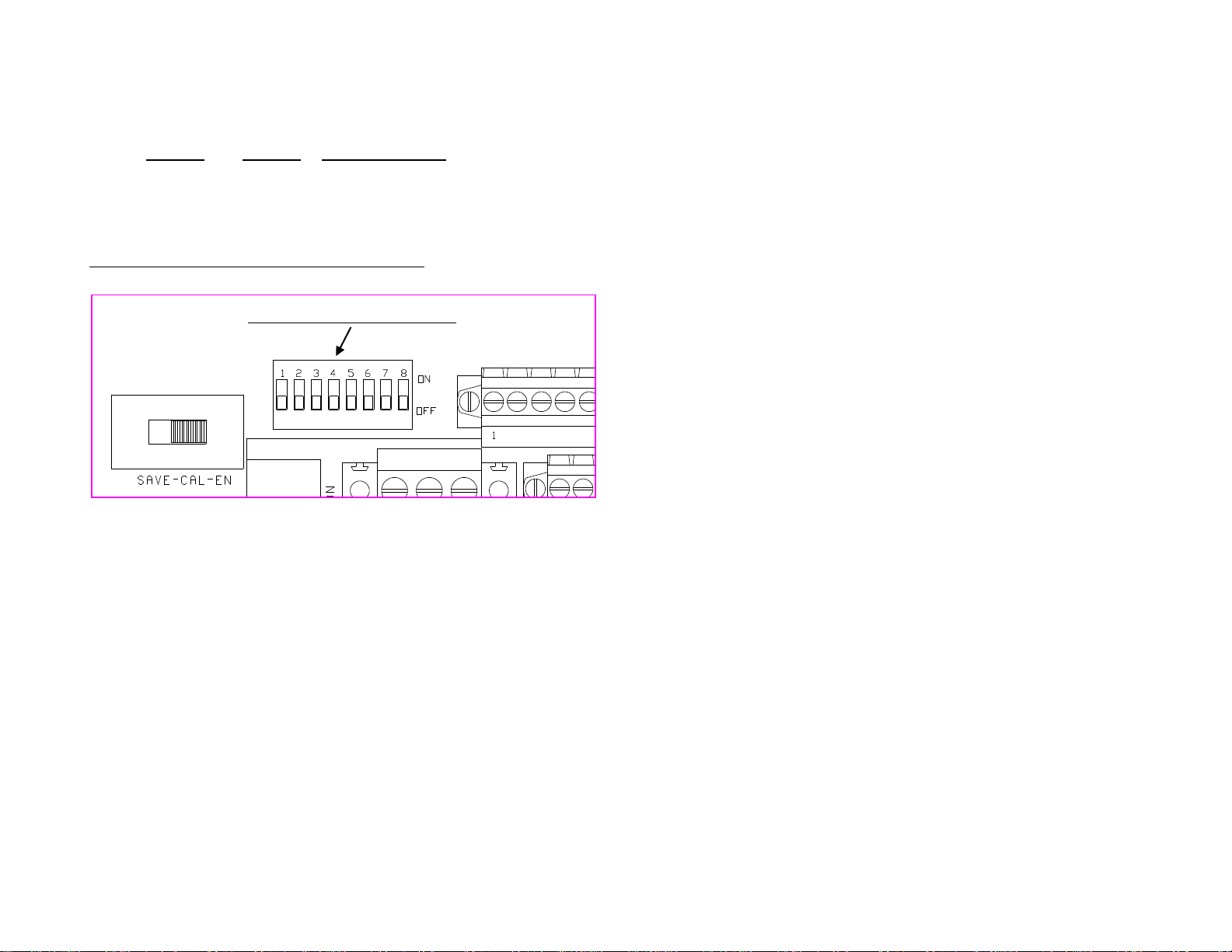
User Calibration Enable Switch
ENabled (right) position: Calibration is enabled (gain and offset adjustments
are active and will affect the torque output signal)
SAVE (left) position: Calibration is saved (gain and offset settings are stored
in memory and adjustment switches are disabled)
User Calibration Offset Adjustment
(Zero Reference Adjustment)
Push DEC switch to decrease torque
output signal offset. Push INC switch to
increase torque output signal offset.
User Calibration Gain Adjustment
(Scale Adjustment)
Push DEC switch to decrease torque
output signal gain. Push INC switch to
increase torque output signal gain.
Remote Shunt Calibration Switch
Used to place a precision “shunt”
resistor across one arm of the full-
bridge strain gage sensor simulating
50% full scale torque.

- 7 -
Torque Signal Calibration Controls
The Revolution System offers several features for fine-tuning the
torque output signal to suit the user’s application. The primary
controls are for adjusting the offset (zero) and gain (scale) of the
system. Other operations include activating the remote shunt
calibration and changing the default zero output signal from
12 mA to 4 mA. All of the controls are described here.
User Calibration Enable –Used to enable the User Calibration
Gain and Offset Adjustments. Specifically, when this switch is in
the EN (enable) position,the GAIN and OFFSET INC (increment)
and DEC (decrement) pushbutton switches are active. (See
description below.) When switched to the SAVE position, the
current offset and gain adjustments are stored in memory and
the GAIN and OFFSET adjustment switches are disabled.
User Calibration Offset Adjustment –Used to manually adjust
the offset (zero reference point) of the torque output signal.
When User Calibration is enabled (see description above),
pressing the OFFSET INC button will increase the offset thus
changing the nominal 12 mA zero reference to a higher value.
Conversely, pressing the DEC button will decrease the offset
thus changing the nominal 12 mA zero reference to a lower
value. The nominal zero reference output of 12 mA can be set to
any output level from 0 –24 mA. Note: Changing the offset
(zero reference) of the torque output signal does not affect the
gain (scale factor) of the torque output signal.
To change the zero reference value from 12 mA to 4
mA (i.e. change the zero-to-positive full scale output
range from 12-20 mA to 4-20 mA) activate Torque
Signal Configuration Switch #3 as described below.
User Calibration Gain Adjustment –Used to manually adjust
the gain (scale factor) for the torque output signal. When User
Calibration is enabled (see description above), pressing the
GAIN INC button will increase the torque signal gain.
Conversely, pressing the DEC button will decrease the torque
signal gain. The torque signal gain can be adjusted to any level
from 25% (¼x) to 400% (4x). Note: Changing the gain (scale
factor) of the torque output signal may affect the offset (zero
reference) of the torque output signal.

- 8 -
Remote Shunt Calibration Switch –Used to verify system
operation without directly accessing the strain gage. When
switched to the ON position, a fixed precision resistance (inside
the Transmitter Module) is applied across one arm of the strain
gage bridge simulating strain that produces a torque signal
output corresponding to 50% of Full Scale in the positive
direction at factory default settings (16mA for 12mA zero torque,
12mA for 4mA zero torque). In the OFF position, the resistance
is removed from the sensor. Note: The System Status Indicator
light flashes (and the internal “Rotor” light flashes) when the
Remote Shunt is applied.
Torque Signal Configuration Switches –Used to set specific
torque signal parameters as listed here. The ON position for
each switch is upwards (towards the Power Ring).
Switch Function when switch is ON:
1 Simulates a positive full scale torque input signal from
the transmitter (nominally generates 20 mA output)
2 Simulates a negative full scale torque input signal from
the transmitter (nominally generates 4 mA output)
1&2 Simulates a zero input signal from the transmitter
(nominally generates a 12 mA output)
3 Full Scale Torque Output Range:
4-20mA with dipswitch #3 ON (up), 4mA zero
12±8mA with dipswitch #3 OFF (down), 12mA zero
4 Reverses the polarity of the torque signal
5 System bypasses the user calibration settings (i.e.
manual gain and offset adjustments are ignored)
6 (Not used)
To restore the factory offset and gain settings:
a) Slide SAVE-CAL-ENable switch to “EN” position
b) Activate dipswitch #5 of Torque Signal
Configuration panel, “Bypass User Calibration”
c) Slide SAVE-CAL-ENable switch to “SAVE” position
d) Deactivate dipswitch #5 of Torque Signal
Configuration panel.
(See Torque Configuration Switch details below.)
- 9 -
7&8 Used to set frequency response of torque signal (i.e.
select cut-off frequency for low pass filter) as follows:
Switch 7 Switch 8 Cut-off Frequency
Off Off 1000 Hz
Off On 12 Hz
On Off 1.5 Hz
On On 0.1 Hz
Factory Default: All switches in the OFF position.
Figure 4 - Torque Signal Configuration Switches
Torque Signal Configuration Switches
- 10 -
Power Output Signal
The 4-20 mA shaft power output signal is accessed from a
removable eight-position screw terminal block on the upper-most
board in the Master Control Unit. Power signal scaling and
configuration switches are described below.
Figure 5 - Power Output Controls and Connections
Power Signal Configuration Switches
Used to set data signal options, e.g.
activating low pass filter or reversing signal
polarity. See table below for details.
Power Signal Output Terminals
Terminal 3 = Power Output Current Loop (+I)
Terminal 4 = Power Output Current Loop Return (Common)
Power Scaling (RPM Factor) Switches
Use these rotary switches to set the scale factor relating the torque signal to
the shaft power signal according to the equation:
PFS x Constant / TFS = RPM Factor.
See details below and in Set Up Procedure.

- 11 -
Power Signal Calibration Controls
The Revolution System offers several features for fine-tuning the
power output signal including adjusting the full scale value and
selecting the frequency response. The power scaling and
configuration controls are described here.
The only offset (zero reference) adjustment for the
power signal is via switch #3 in the Power Signal
Configuration Switch panel. (See details below). If
Power Configuration switch #3 is not activated a power
output signal of 12 mA will always indicate zero power
and zero power will always correspond to zero torque
and/or zero RPM.
Power Scaling (RPM Factor) Switches –Used to set the full
scale range for the power output signal (as described in the Set
Up Procedure). There are four rotary switches corresponding to
thousands (x1000), hundreds (x100), tens (x10) and units (x1).
The switches are set by using a small screwdriver to turn the dial
indicator to the desired digit and then cycling system power.
Note: System must be turned OFF then ON (using Main Power
Switch) to register new RPM factor switch settings!
For example, if the calculated RPM Factor is 1490 then the
switches would be set as follows:
x1000 -position 1
x100 -position 4
x10 -position 9
x1 -position 0
IMPORTANT: Power supply to the TorqueTrak Revolution must
be cycled Off, then back On, to make effective any changes to
the RPM Factor switch setting.
Note: The power signal gain (sensitivity) is dependent
upon and proportional to the torque gain.
Power Signal Configuration Switches –Used to set specific
power signal parameters as listed here. Note: The ON position
for each switch is upwards (towards the Power Ring).

- 12 -
Switch Function when switch is ON (Factory Default: All OFF):
1 Generates positive full scale power output signal (20mA)
2 Generates negative full scale power output signal (4 mA)
1&2 Generates zero power output signal (12 mA)
3 Full Scale Power Output Range:
4-20mA with dipswitch #3 ON (up)
12±8mA with dipswitch #3 OFF (down)
4 Reverses the polarity of the power signal
5 Updates power output signal once per shaft revolution
6 Normally OFF. ON for very low speed shafts (<10 RPM)
7&8 Used to set frequency response of power signal (i.e. select cut-
off frequency for low pass filter) as follows:
Switch 7 Switch 8 Cut-off Frequency
Off Off 1000 Hz
Off On 12 Hz
On Off 1.5 Hz
On On 0.1 Hz
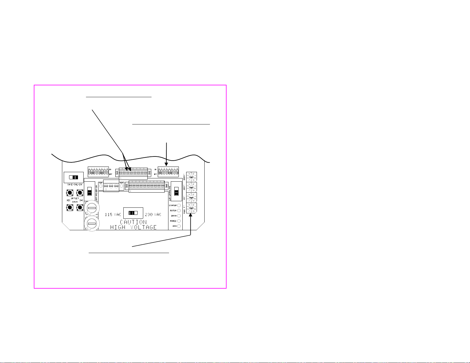
Figure 6 - Power Signal Scaling and Configuration Switches
Power Scaling (RPM Factor)
Switches
Power Signal Configuration
Switches

- 13 -
When switch #3 is activated the output signal at zero power
changes from 12 mA to 4 mA and simultaneously the signal gain
is doubled.
When Switch #5 is OFF, the power output signal is calculated
and updated 6 times per shaft revolution (i.e. whenever the RPM
sensor is triggered). When Switch #5 is ON, the power output
signal is calculated and updated only once per shaft revolution
thereby averaging the power data over a complete revolution.
Switch #6 is used when the shaft speed is very low (less than 10
RPM). When Switch #6 is ON the system adds a delay between
the time the RPM sensor is triggered and the time the power
output signal is allowed to indicate zero power. This feature
prevents a slowly rotating shaft from erroneously generating a
zero power data signal.

- 14 -
Speed (RPM) and Direction Output Signals
The 5 or 19mA speed (RPM) and direction output signals are
accessed from a removable eight-position screw terminal block
on the upper-most board in the Master Control Unit as described
below.
Figure 7 - Speed and Direction Output Connections
The speed (RPM) output signal is a pulse train that is nominally
5 mA or 19 mA (depending on shaft direction) which pulses to
the alternate current level at the following rate:
RPM
FPULSE = ------------
10
FPULSE = Frequency of the pulse train in Hertz
RPM = Shaft revolutions/minute
Direction Signal Output Terminals
Terminal 7 = Direction of Rotation Output Current Loop (+I)
Terminal 8 = Direction of Rotation Output Current Loop Return (Common)
Speed (RPM) Signal Output Terminals
Terminal 5 = Speed Output Current Loop (+I)
Terminal 6 = Speed Output Current Loop Return (Common)

- 15 -
When viewed from the front of the Master Control Unit with the
coil board on the Rotating Collar in view a clockwise rotation
produces a speed signal that is nominally 19 mA with 5 mA
pulses. Conversely a counterclockwise rotation produces a
speed signal that is nominally 5 mA with 19 mA pulses.
Six magnets in the Rotating Collar trigger the pickup sensor in
the Mounting Block on top of the Master Control Unit to generate
the speed signal.
The direction signal is a simple binary indicator, 5 mA when the
shaft rotates in one direction and 19 mA when it rotates in the
other direction.
Clockwise Shaft Rotation:
Direction signal:19 mA, constant
Speed signal: 19 mA, pulsing to 5 mA at the rate of 6 pulses
per revolution
Counterclockwise Shaft Rotation:
Direction signal:5 mA, constant
Speed signal: 5 mA, pulsing to 19 mA at the rate of 6 pulses
per revolution
NOTE: The maximum load resistance of any one of the
TorqueTrak Revolution output current loops is 500 ohms. This
means the system can drive the 4-20 mA output signal into
resistances of 0 to 500 ohms. To calculate the distance the
signal can travel, add the input resistance of the device you plan
to “drive” plus the resistance of the wire length. As long as the
total resistance is less than 500 ohms, the TorqueTrak
Revolution output signal will drive the device.

- 16 -
System Status Indicator Lights
There is one Main System Status Indicator light located outside
the Master Control Unit at the base of the Power Ring and five
secondary system status indicator lights inside the unit. See
Appendix C: Error Codes & Troubleshooting for indicator details.
Figure 8 - System Status Indicators
Secondary System Status Indicators
Stator (Green) = On solid if input power level is in range
Rotor (Green) = On solid if collar power is in range and no data errors
Data (Green) = On solid if no data transmission errors
Range (Red) = Off if sensor input signal is within range
RPM (Green) = At slow shaft speeds used to verify operation of RPM
sensor. LED flashes as magnets trigger pickup sensor.
(See Appendix C for more details.)
Main System
Status Indicator
Red light is on solid if no
system errors are present
- 17 -
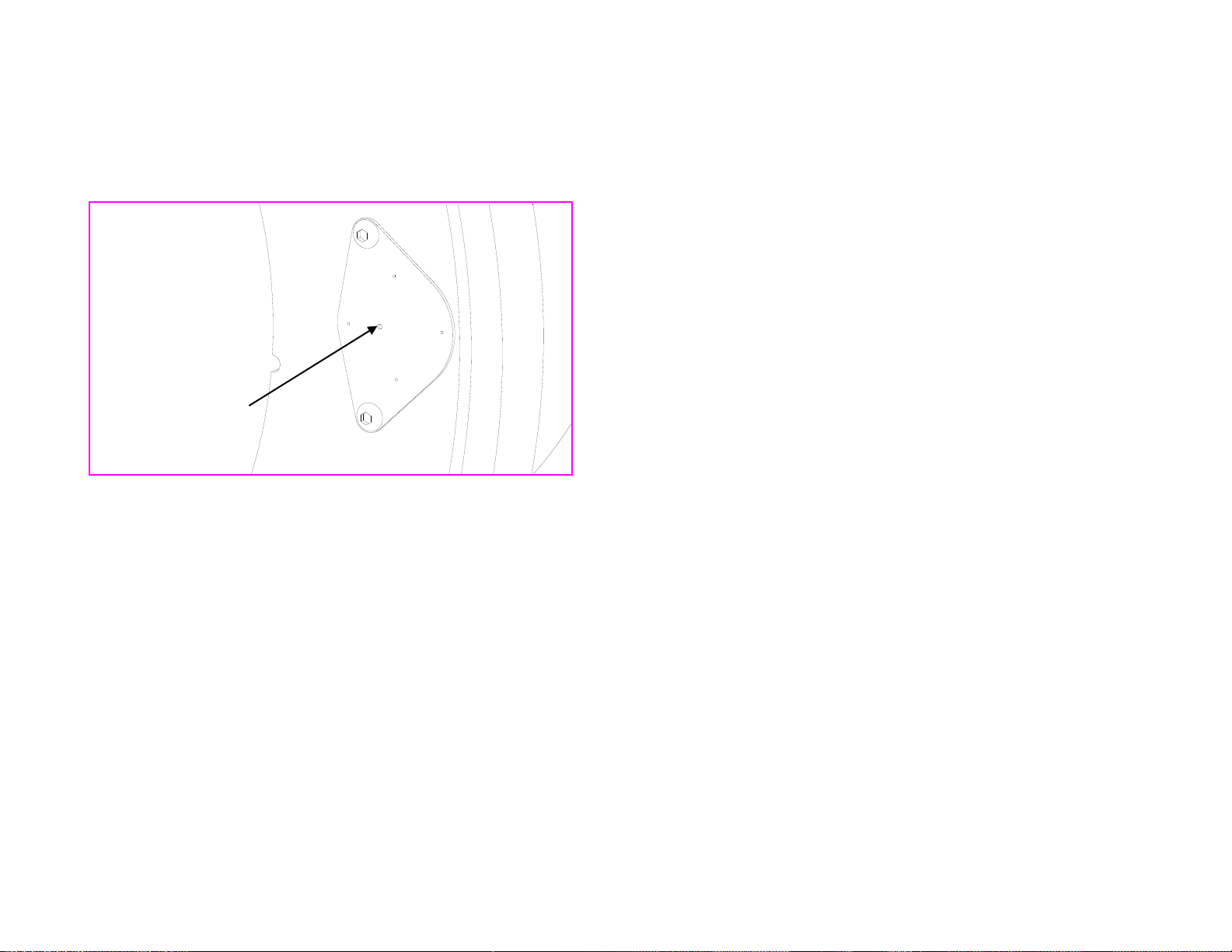
Transmitter Status Indicator Light
The green light embedded in the cover of the transmitter module
(located on the back side of the Rotating Collar) is the
Transmitter Status Indicator Light.
Figure: Transmitter Status Indicator Light
When the Transmitter Status Indicator Light is on solid, the
transmitter module is receiving sufficient power from the rotating
coil and is sending out viable digital data.
This indicator is most useful when troubleshooting an error mode
(refer to Appendix C). When the error mode is “weak inductive
link” (i.e., Main System Status light is flashing fast, Stator light is
on solid, Rotor and Data lights are off or blinking) and the
Transmitter Status Indicator is on, it means that the transmitter is
still receiving enough power to send data, but the data signal
being sent to the MCU is not being received. If the light is off,
this may indicate that insufficient power is being supplied to the
transmitter or that the transmitter module has failed. In either
case, follow the corrective actions outlined in Appendix C.
Transmitter
Status Indicator
Light
- 18 -
Installation Procedure
1. If not already installed, attach strain gage(s) (or other
sensors) to shaft being measured. (See Appendix D: Strain
Gage Application for simplified instructions.)
2. For 4-piece Rotating Collars and Power Rings, pre-assemble
half-sections using hardware and instructions provided.
Make sure 4-piece collar sections are assembled in the
correct order, otherwise speed and power sensing
features will not function properly.
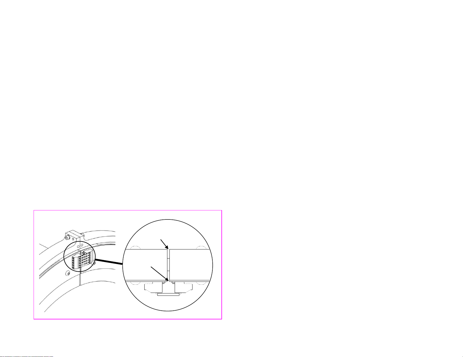
3. Apply anti-seize compound (provided) to threads of collar
bolts. Assemble collar on shaft adjacent to gage with ribbon
cable from collar leading towards gage. (Refer to Figure 1
on page 3 or Figure 10 on page 20.) Install opposing collar
bolts from opposite directions to maintain balance. Tighten
alternate bolts evenly until gap between collar halves is .100”
(2.5mm) at all junctions. (See Figure 9 below.)
CAUTION: Before proceeding make sure bolts
are tight enough to prevent loosening while
rotating but not so tight that the boards attached
to the Rotating Collar are interfering with each
other.
Figure 9 - Correct Collar Gap Spacing
jumper wire
0.100” (2.5 mm)
0.020” (0.5 mm)

- 19 -
4. After collar is bolted on the shaft, place jumper wires
(provided) in the screw terminal connectors at each collar
junction as shown in Figure 9 and tighten securely.
5. Assemble one half of Power Ring to Master Control Unit
using hardware provided. Position Master Control Unit with
half-ring around shaft and assemble second half of Power
Ring.
6. Securely mount Master Control Unit to machine or mounting
plate (not provided) so that the Rotating Collar is centered
within the Power Ring. (Refer to Figure 1 on page 3 or
Figure 10 on page 20.) For larger systems, use the Support
Brackets provided to stabilize and support the Power Ring
with additional braces.
7. Remove cover from Master Control Unit. Install cable clamps
or conduit connectors (not provided) in holes in bottom of
box. Route data signal wires from process control or
recording equipment through clamps or connectors then
connect to corresponding screw terminals (black connector)
inside unit. Note: Wiring holes must be sealed accordingly
to prevent contamination in the enclosure.
8. Route electrical power wires through clamps or connectors
then connect to corresponding electrical power terminals
(green connector) inside unit.
NOTE: Steps 9-11 outline verification of system
operation. A star bridge has been pre-wired to
the Revolution transmitter for this purpose.
Completing the verification will greatly reduce
troubleshooting effort if a system error exists.
9. Slide main power switch to ON. After 10 seconds, verify that
Main System Status light is on solid, indicating successful
data transmission. If Main System Status light is flashing,
see Appendix C: Error Codes & Troubleshooting.
10. Connect an amp meter (not provided) to the Torque Signal
Output Terminals (1 & 2) inside MCU. Measure the Torque
Signal (mA). Reading should be approximately 12 mA.
Other manuals for TorqueTrak Revolution
1
Table of contents
Other Binsfeld Measuring Instrument manuals


