Biobase BOV-V30F User manual

Forced Air Drying Oven
BOV-V30/45/65/125/230/625F
User Manual
BIOBASE GROUP
Version 2020.07

1
Preface
Thank you for purchasing BIOBASE Drying Oven.
Using object
This manual is intended for the laboratory technologists operating this instrument. Before using the
product, please carefully read this manual. Keep this manual in a safe place for easy reference. If you
do not follow the precautions described in this manual, we will not guarantee the maintenance.
Statement
Jinan Biobase Biotech Co., Ltd (hereinafter referred to as "Biobase") has the final interpretation of
this manual.
The Company shall be responsible for the safety, reliability and performance of the product only if
all of the following requirements happened:
1.Assembly operations, expansion, re-adjustment, improvement and repair by the Company
recognized professionals.
2.All repairs involving replacement parts and supporting the use of accessories, supplies are original
of the Company (original) or approved by the Company.
3.The related electrical equipment is according to national standards and the use of the manual
requirements.
4.Product operation is carried out according to the instruction manual.
Disclaimer
Biobase shall not be liable for any equipment failure or damage, or for any direct or indirect damage
that may occur during the use of the equipment.
1.Malfunction or damage due to violation of the instructions, precautions, and intended use of this
manual.
2.Malfunction or damage caused by repair or alteration of the other company.
3.Malfunction or damage caused by use instruments of other company at the same time.
4.Malfunction or damage caused by operating environment not corresponding to the specified
operating environment (power conditions, installation environment, etc).
5.Malfunction or damage caused by natural disasters such as earthquakes and floods.
6.Malfunction or damage caused by the company unaware of the movement or transfer (transport)
after installation.

2
Content
Preface.................................................................................................................................................... 1
1. Installation and Operating Conditions................................................................................................3
2. Product Structure................................................................................................................................3
3. Technical Parameters..........................................................................................................................4
4. Control Panel...................................................................................................................................... 5
5. Instructions of Operation....................................................................................................................6
6. Wiring Diagram.................................................................................................................................. 9
7. Trouble Shooting................................................................................................................................ 9
8. Warranty........................................................................................................................................... 10

3
1. Installation and Operating Conditions
1.1. This equipment should be placed in a room with good ventilation, shading, and cool conditions.
The equipment and walls must be more than 10 cm away. Do not place flammable or explosive
materials around it.
1.2. When the equipment is used for the first time, there may be slight fumes and odors due to spray
and rust-proof coating. This does not affect the use, it will disappear after one or two uses. Therefore,
it is best to open the doors and windows for a while when using for the first time.
1.3. The power box should be in accordance with the specified voltage and be reliably grounded to
ensure safe use.
1.4. Do not place excessively indoor objects. Space for air convection must be allowed to facilitate
hot air circulation and discharge of humid exhaust gas.
1.5. When the door is opened or the item is put in for a long time, the temperature setting should be
lowered or the power switch should be turned off for 5 to 10 minutes (depending on the length of the
door opening time) to reduce the occurrence of temperature and avoid unnecessary loss.
1.6. In order to maintain the appearance of the equipment, please do not use acid or alkali and other
corrosive materials to wipe the surface, the box can be cleaned regularly with a dry cloth.
1.7. The fuse box of the equipment is equipped with a fuse. If the equipment is not energized, first
check whether the fuse tube is in good condition. Please cut off the power when checking and
replacing the fuse tube. And replace the same type of fuse tube.
1.8. The oven doesn’t have explosion-proof function, do not put flammable and explosive substances
in.
1.9. Please turn off the power after using.
2. Product Structure
2.1. External material: cold-rolled steel with anti-bacteria powder coating.
2.2. Stainless steel inner chamber, round angle structure, adjustable shelves.
2.3. Double-layer glass observation window, adjustable airtight buckle lock.
2.4. PID microprocessor intelligent temperature controller.
2.5. Over-temperature protection.
2.6. Optional independent temperature protector

4
3. Technical Parameters
Model
BOV-V30F
BOV-V45F
BOV-V65F
BOV-V125
F
BOV-V230
F
BOV-V625F
Capacity
30L
45L
65L
125L
230L
625L
Temp. Range
RT+5~300℃
Temp. Precision
0.1℃
Temp.
Fluctuation
±0.5℃
Ambient Temp.
5~40℃
Timing Range
1~9999min
Shelves No.
2 pcs
3 pcs
Power
Consumption
800W
1200W
1600W
2300W
3000W
5000W
Power Supply
220V±10%, 50/60Hz
380V/50HZ
Internal
Size(W*D*H)
mm
310*310*31
0
350*350*35
0
400*360*45
0
500*450*55
0
600*500*75
0
660*760*125
0
External
Size(W*D*H)
mm
460*510*69
5
500*550*73
5
540*550*84
0
636*680*91
5
730*670*12
20
895*925*183
0
Packing Size
(W*D*H) mm
550*570*76
5
620*585*80
0
640*640*90
5
730*720*10
00
900*800*13
50
1000*1080*2
000
Gross
Weight(kg)
51
56
61
71
105
160

5
4. Control Panel
1. Measured value display 6. Shift key,
2. Setting value display 7. Addend key
3. Alarm 2 indicator 8. Reduction key
4. Alarm 1 indicator 9. Main control output indicator
5. Set key 10. Auto tuning indicator

6
5. Instructions of Operation
The upper row of digital tubes displays the measured temperature, and the lower row displays the set
temperature
Press the SET key shortly, the temperature setting state will be entered
The parameters can be corrected by the▼, ▲ keys, press the SET key to enter the time setting state
Adjust time by After the▼, ▲ keys, after confirm, return to normal display screen.
AT (temperature auto tuning)

7
It need to re-adjust the temperature if the temperature fluctuations is more than 5 degrees, or can’t
meet the requirements of the temperature.
For example:
After setting the required temperature of 100 degrees, press the button 5 seconds, AT indicator
is on, then enter the auto tuning state. Can’t open the door or pump, can’t reset, can’t shut off the
power in this process. The meter will automatically calculate the heating rate. AT indicator will be off
after 30 mins. the instrument will control the temperature according to new program and in order to
achieve high precision temperature control.
Parameter list:
Code
Value range
Function
Factory value
SP
SPL~SPH
Temperature setting
Random
ST
0~9999min
Time setting
0
press set key over 5 seconds
Lock
0~9999
Parameter lock
0
SC
-50.0~+50.0℃
Process value biasing
0℃
SCK
0.700~1.300
Process value sloping
1.000
Lock: ××××(But ask the manufacturer for)
P
0.1~50.0℃
Proportional Band
5.0℃
I
1~400
Integral Time
40s
d
0~100
Derivative Time
10s
T
1~200
Control Period
20s(2s)
AL1
-20~+20℃
alarm value
5℃
ET
0~2
Function option the regular time
2
dP
0~1
Point changing
1
PT
1~30min
Print gap time
1min
Addr
0~32
This machine mail address
0
Pr
1~100
Upper limit constant temperature
power percentages
20%
SPL
Measuring range
lower limit ~SPH
Temperature setting value lower
limit
Measuring range lower
limit
SPH
SPL~ Measuring
range upper limit
Temperature setting value upper
limit
Measuring range upper
limit
Description:
1) Through press or < key, revise parameters rapidly,The necessaries being over affirms
modification according to set key, Otherwise invalidate. Think that Lock is 0, Only when SC/
SCK is parametric may revise; Think that Lock is XXXX,Except SC /SCK, all parameters may
revise.
2) SC is process value biasing, SCK is process value sloping. May amend the measurement error
that cause from sensor to other arouses. Be in appearance when not having been amended
(SC=0;SCK=1.000), While zero position error of appearance is bigger may adjust SC,SC=
Standard value -Measure value; While full degree error of appearance is bigger may adjust

8
SCK,SCK= Standard value / Measure value.
3) P for setting proportional band. When take place regular oscillation of controlled temperature, the
proportional band should be increased and if controlled temperature drifts irregularly we ought to
decrease the proportional band.
4) I for setting the integral time. When the system takes place regular oscillation ought to I for
setting proportional band. When take place regular oscillation of controlled temperature, the
proportional band should be increased and if controlled temperature drifts irregularly we ought to
decrease the proportional band. ncrease integral time and if the system controlled can not remove
the static deviation in a long time ought to decrease the integral time.
5) D for setting the derivative time. Increasing the derivative time can decrease the overshoot of the
system.
6) T is Control Period, Relay output ≮20s,SSR and thyristor output≮3s continuous output,1s.
7) AL1 is alarm value 1, Measure value giving an alarm after deflecting setting value ∣AL1∣℃,
AL1 is set up giving an alarm for being to reach the end point at 0,
Upper limit alarm for AL>0,
low Limit alarm for AL<0.
8) At the regular time function option parameter ET is 0,No regular time function,Time sets up a
menu concealing;ET is 1 or 2,Demonstrate time setting up menu ST. If ST is 0, Do not mind
time then, ET is 1, After the electricity on the instrument, Reckon by time beginning, ET is 2,
While the temperature reaches setting value start timing. Adopt countdown way at the regular
time, Begin to reckon by time,
the upper row displays the Remain in time value,
Reckon by time
being over, the upper row displays STOP,
Run stoppage,
Export a cutoff, Have intermittent buzz
sound prompting at the same time, Push down any key but noise reduction. After press start/stop
key over 3 seconds, Can start or stop procedure work.
9) dP is that the temperature is sure to change option , dP is 0 , temperature display has no point,
dP is 1 , temperature display has point.
10) Pr is Upper limit constant temperature power percentages, Generally, The function big or
preserving heat if systematic power allocation is prejudiced is very good, Pr value responds to
small, Can prevent from rushing the temperature; Whereas Pr value responds to then big, Can
improve litre of temperature speed. One system is different generally in different setting up under
the temperature from P , I , D parameter that adjust reaches, Suggest setting up temperature
adjusting parameter being able to reflect system inertia nearby in the room temperature, But be
used for the high temperature litre of temperature is possibly slower time end, Effect adjusting Pr
value now being ok to make system can reach very good controlling within entire range.
9
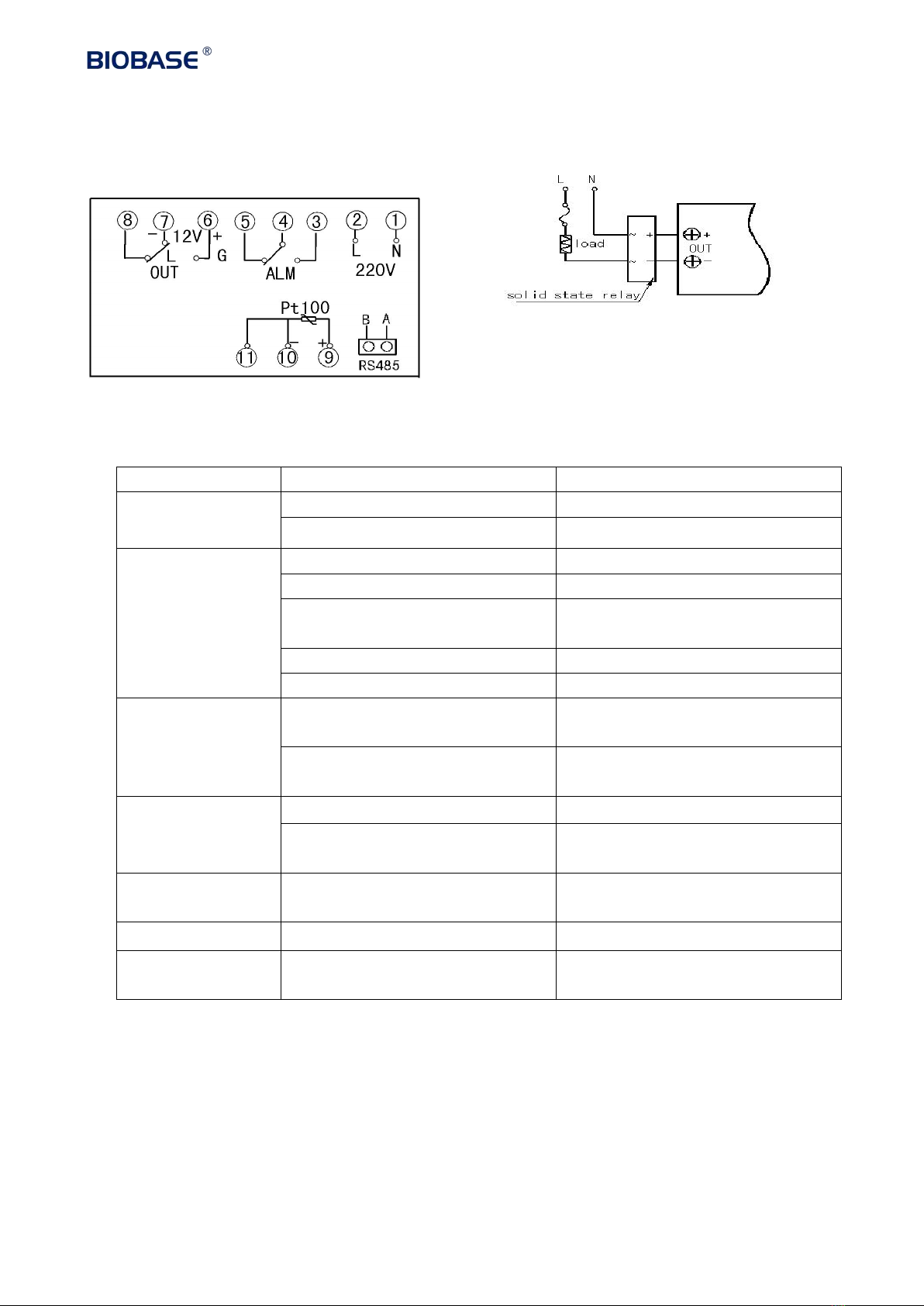
6. Wiring Diagram
7. Trouble Shooting
Common failures and Solutions:
Phenomena
Causation
Treatment Method
No power supply
a. poor plug contact or line broke
a. Connect the plug and line.
b. Fuse protector is broken.
b. Change the fuse protector.
No temperature
rising inside
container
a. Low setting temperature
a. Readjust and set temperature
b. Heater is broken.
b. Change the heater
c. Temp. controller is broken
c. Change the temperature
controller
d. Temp. sensor is loose.
d. Screw up the sensor nut.
e. Temp. sensor is broken
e. Change the temperature sensor.
No temperature
rising alarm
a. Set temp. of Detached tem.
limiter is low
a. Readjust the temperature 30℃
above setting temperature.
b. Detached temp. limiter sensor
is broken.
b. Change the detached temperature
limiter sensor
Temperature cannot
reach the setting
point.
a. Exhaust port is fully opened
a. Shut off the exhaust port.
b. The container is overfilled, no
hot air convection.
b. Decrease amount of sample to
improve convection condition.
The fan doesn’t
work.
The fan motor is broken
Stop work and check electric
capacity and motor
Displaying-------
The sensor is broken
Change the sensor
Display STOP
Time-up
Press the program key for 3s to
start

10
8. Warranty
8.1. Warranty is 12 months from EX-factory date (excluding consumable accessories).
8.2. Biobase would not be liable for any repair of damage caused by improper operation.
8.3. If the warranty has been expired, Biobase would still responsible for repair with relative charges.
8.4. Biobase would provide necessary technical data for maintenance companies or personnel trained
by Biobase engineers.

11
BIOBASE GROUP
2# building, No.9 Gangxing Road, High-tech Zone, Jinan City, Shandong Province,
China
Tel: +86-531-81219803/01
Fax: +86-531-81219804
Inquiry: [email protected]m
Complaints: custom[email protected]
Web: www.biobase.cc/www.meihuatrade.com / www.biobase.com
Other manuals for BOV-V30F
1
This manual suits for next models
5
Table of contents


