biochrom HB Ultrospec 7500 User manual

ORIGINAL INSTRUCTIONS •41 56 2050 REV03 •
1
Ultrospec 7500
Spectrophotometer
USER MANUAL

Ultrospec 7500 User Manual • 41 56 2050 REV03 •
2
Intentionally blank

Ultrospec 7500 User Manual • 41 56 2050 REV03 •
3
TABLE OF CONTENTS
ESSENTIAL SAFETY NOTES 7
Hazards and Warnings 7
INTRODUCTION 8
The Biochrom Ultrospec Spectrophotometers 8
INSTALLATION 9
Unpacking 9
Positioning 9
Installing 9
WARRANTY AND REPAIR 10
Warranty Policy 10
Returns 10
INSTRUMENT OVERVIEW 11
Scope 11
Spectrophotometer Principle and Intended Use 11
Hardware 11
Technical Specifications 12
Touchscreen Display 12
Instrument Connections 12
PVC PC Software 13
Biochrom Resolution PC Software 13
Instrument Data Output 13
Performing a Measurement 13
USER INTERFACE 14
Colour Touchscreen 14
Onscreen Keyboards and Number Pad 14
Frequently Used Icons 15
Navigating Icons 15
Common Icons on the Sample Measurement Screen 15
Common Icons on the Options Menu 16
Home Screen Toolbar Icons 16
Instrument Firmware 17
First-time Start-Up 17
Home Screen 17
Login Screen 18
Power Off 19
Settings 19
Date and Time 19
Regional 20
Data Output 20
User Interface 20
Accessories 21
User Access 21

Ultrospec 7500 User Manual • 41 56 2050 REV03 •
4
GLP Settings 23
GLP application 23
GLP error 23
Switch User 24
Instrument Status 24
Instrument Information 24
Instrument Settings 25
Lamp Settings 25
Instrument Reset 26
Applications 27
Single Wavelength 27
Wavescan 30
Kinetics 34
Standard Curve 38
Substrate 43
Equation Editor 48
Protein 52
Protein UV 52
Colorimetric Protein 55
Protein Dye 60
DNA 64
RNA 67
Oligo 70
Fluorescent Dye 73
OD 600 78
Tm Calculation 80
Methods 83
Favourites 85
USB Methods 85
Sample Manager 86
Additional Options 87
Options Menu Icons 87
Status Bar Icons 88
Taking and Saving Screenshots 88
USEFUL CALCULATIONS 89
Beer-Lambert Law 89
Nucleic Acid Concentrations 90
Protein Concentrations 91
Nucleic Acid and Protein Purity Ratios 92
Fluorescent Dye Quantity 93
Fluorescent Dye Concentration 93
Fluorescent Frequency of Incorporation (FOI) 93
Fluorescent Dye Incorporation 93
Melting Temperature (Tm) 94
OD 600 96

Ultrospec 7500 User Manual • 41 56 2050 REV03 •
5
TROUBLESHOOTING 97
PRINTING 98
Printing Sample Data 98
External Printer 98
Print Via Computer (PVC) 98
Manual Printing 98
Installing the External Printer 99
ACCESSORIES 101
Accessory Part Numbers 101
Accessory Installation Guide 101
CONTACT INFORMATION 102

Ultrospec 7500 User Manual • 41 56 2050 REV03 •
6
Intentionally blank

Ultrospec 7500 User Manual • 41 56 2050 REV03 •
7
ESSENTIAL SAFETY NOTES
Hazards and Warnings
This section describes potential hazards which may exist in the operation of these units. Several warning labels and symbols are affixed to
your instrument. These symbols are used to inform you of potential dangers which may exist or where caution is required. Before installing
your new unit, please take time to familiarise yourself with these warnings and symbols.
N.B. THE PROTECTION GIVEN BY THE EQUIPMENT MAY BE IMPAIRED IF USED IN A MANNER NOT SPECIFIED BY THE MANUFACTURER.
This instrument is subject to the following identified hazards:
This unit uses a Xenon lamp. The lamp energy is mainly confined within the unit but traverses the cell holder when a
measurement is being taken. Although the energy present is low and intermittent you are advised not to stare into the beam
or attempt to deflect the beam as prolonged exposure could result in permanent eye damage.
High voltages existwithin the power supply unit and the Xenon lamp housing. Repair and maintenance should only be carried
out by individuals trained to work on these instruments.
There are no biohazardous materials within the unit, however, this unit may be exposed to biohazardous samples during
normal laboratory use. To protect users against these hazards we recommend the following decontamination procedures:
•Wipe the exterior casework with disinfectant cleaning wipes.
•Remove cuvettes and cuvette holders.
•Wash with disinfectant appropriate for the biohazard in question.
•Rinse with distilled water.
•Allow to dry thoroughly before reuse.
To further reduce the possibility of biohazards:
•Include an appropriate decontamination certificate for equipment returned for repair.
•Ensure that the operator of the equipment is provided with a safe working environment.
•Use, store and dispose of any chemicals in accordance with manufacturer’s guidelines and local safety regulations.
•Provide suitable ventilation when working with volatile solvents or toxic substances.
•Dispose of solvents and chemicals that may be classed as hazardous waste in accordance with local regulatory practice.
•Determine if personal protective equipment (PPE) is required for handling laboratory samples.
All models can be connected to and operated from a PC. To preserve the integrity of the measuring equipment it is essential
that the attached PC itself conforms to basic safety and EMC standards and is set up in accordance with the manufacturers’
instructions. If in doubt, consult the information that came with your PC.
The following safety precautions should be observed when operating a PC:
•To reduce the chance of eye strain, set up the PC display with the correct viewing position, free from glare and with
appropriate brightness and contrast settings.
•To reduce the chance of cross contamination from biological samples, use appropriate personnel protection measures
and disinfectant wipes on keyboard and mouse.
In the event of contamination, malfunction or hazard occurring, the operator should disconnect the unit, by removing the
power cord, and isolate for decontamination and/or repair.

Ultrospec 7500 User Manual • 41 56 2050 REV03 •
8
INTRODUCTION
The Biochrom Ultrospec Spectrophotometers
Spectrophotometers are ubiquitous among modern laboratories. Ultraviolet (UV) and Visible (VIS) spectrophotometry has become the
method of choice in most laboratories concerned with the identification and quantification of organic and inorganic compounds across a
wide range of products and processes. Applied across research, quality, and manufacturing, with continuing focus on life science and
pharmaceutical environments, they are equally as relevant in agriculture, animal husbandry and fishery, geological exploration, food safety,
environmental monitoring, and many manufacturing industries to name a few.
The Ultrospec spectrophotometers are quick, accurate, and reliable. They require only small demands on the time and skills of the operator.
This operating manual details the processes in taking basic measurements using the Ultrospec 7500 spectrophotometer.
The Ultrospec 7500 instrument is UV-VIS split-beam spectrophotometers with a 2 nm spectral bandwidth and comes as standard,
with a 10 mm pathlength 8 position cell changer, however a range of alternative accessories are available.

Ultrospec 7500 User Manual • 41 56 2050 REV03 •
9
INSTALLATION
Unpacking
•The unit weighs ~13 kg. No special handling is required.
•Please keep the original packaging for transport for service or repair as it has been specifically designed to protect the unit from damage
during transit.
•Inspect the instrument and its power supply for any signs of damage caused during transit. If any damage is discovered, do not use the
instrument, and report the problem to your supplier.
Positioning
•Ensure your proposed installation site conforms to the environmental conditions for safe operation:
•Indoor use
•5 to 40°C
•Maximum relative humidity 90% up to 31°C decreasing linearly to 50% at 40°C.
•Extremes of temperature may require recalibration of the unit for optimal performance.
•The instrument must be placed on a stable, level bench or table capable of supporting its weight allowing sufficient space
around the instrument for air to circulate freely.
•The instrument should be positioned so that the power supply cable may be readily removed in the event of a hazard or
malfunction.
•Locate the instrument in an atmosphere free from dust and corrosive fumes. Use the dust cover to further protect the
instrument when not in use.
Installing
•If the instrument has been stored in a cold environment, then it should be allowed to come to room temperature before
turning it on to avoid compromising the internal calibration procedure.
•The equipment is operated using a 19 VDC power supply adapter unit. Always use the power supply adapter and mains cords
supplied with the instrument.
•Mains power requirements are as follows:
•100 to 240 VAC~
•50 or 60 Hz
•The UK style mains cord plug has a user replaceable 3A fuse. Replace only with the same rating and type 3A BS1362.
•The unit maximum power rating is 90 VA.
•Connect the instrument to the mains power using the main power cord and the 19 VDC power supply adapter unit, then turn
the instrument’s main switch to the on (I) position, this will Power on the instrument followed by a series of self-diagnostic
checks.
Main switch and 19 VDC power supply socket

Ultrospec 7500 User Manual • 41 56 2050 REV03 •
10
WARRANTY AND REPAIR
Warranty Policy
Biochrom warrants these instruments for a period of 24 months (2 years), and an additional 12 months (3 years in total) for the xenon lamp,
from the date of purchase. Where appropriate, Biochrom will repair or replace the unit for defects of workmanship or materials. This
warranty does not extend to damage resulting from misuse, neglect, or abuse, normal wear and tear, or accidental damage. This warranty
extends only to the original purchaser.
Products failing within the first 30 days of end user operation are considered dead on arrival (DOA) and where appropriate a replacement
will be given if a repair is not possible. In the instance of a DOA Biochrom will incur the return shipping charges.
IN NO EVENT SHALL BIOCHROM BE LIABLE FOR INCIDENTAL OR CONSEQUENTIAL DAMAGES. Some states do not allow the exclusion or
limitation of incidental or consequential damages so the above limitation to exclusion may not apply to you. THERE ARE NO IMPLIED
WARRANTIES OF MERCHANTABILITY, FITNESS FOR A PARTICULAR USE, OR OF ANY OTHER NATURE. Some states do not allow this limitation
on an implied warranty, so the above limitation may not apply to you.
Returns
If any defect arises within or outside the warranty period, please contact:
US Office Technical Support
Email
support@hbiosci.com
Online Returns form
https://support.biochrom.co.uk/hc/en-
us/requests/new?ticket_form_id=1500000731442
Telephone (Toll Free)
+1 800 272 2775
Telephone (Outside the US)
+1 508 893 8999
Address
84 October Hill Road
Holliston MA 01746
USA
UK Office Technical Support
Email
support@hbiosci.com
Online Returns form
https://support.biochrom.co.uk/hc/en-
us/requests/new?ticket_form_id=1500000731442
Telephone
+44 (0) 1223 423 723
Address
Unit 7, Enterprise Zone
3970 Cambridge Research Park
Beach Drive, Waterbeach
Cambridge, United Kingdom
CB25 9PE
Goods will not be accepted for return unless an RMA (Return Materials Authorization) number has been issued. The unit must be
returned only once the online RMA form has been completed and submitted, and an RMA number has been issued. The customer is
responsible for shipping charges unless the failure is within 30 days of receiving the goods. Please allow a reasonable amount of time
for completion of repairs or replacement.

Ultrospec 7500 User Manual • 41 56 2050 REV03 •
11
INSTRUMENT OVERVIEW
Scope
This user manual covers the following range of Biochrom UV/Visible spectrophotometers:
Part Number
Description
80-2140-60
Ultrospec 7500
Spectrophotometer Principle and Intended Use
UV/Visible spectrophotometers measure the transmission of light through a sample. Samples absorb light based on their unique molecular
composition. The amount of absorbance is directly proportional to the sample concentration and the pathlength, which is the distance that
the light travels through the sample.
UV/Visible spectrophotometers are used in a number of different laboratory environments including life science, clinical, healthcare and
industrial laboratories. In a life science laboratory, UV/Visible spectrophotometers are commonly used to measure the concentration of
nucleic acids and proteins.
Hardware
Your spectrophotometer is a simple-to-use UV/Visible instrument with two silicon photodiodes. A 1200 lines/mm aberration corrected
concave grating mounted on a calibrated motor, which is the basis of the quick and accurate scanning operating system.

Ultrospec 7500 User Manual • 41 56 2050 REV03 •
12
Technical Specifications
Wavelength range
190 to 1100 nm
Monochromator
1200 lines/mm Aberration corrected concave grating
Wavelength calibration
Automatic upon switch on
Beam Height
15 mm
Spectral bandwidth
<2 nm
Wavelength accuracy
±1 nm
Wavelength reproducibility
±0.5 nm
Light sources
Xenon flash lamp
Detector
two silicon photodiodes
Photometric range
-3.000 to 3.000 A, 0.1 to 100000 %T
Photometric accuracy
±0.5 % or ±0.003 A whichever is greater at 546 nm
Photometric reproducibility
±0.5 % to 3.000 A at 546 nm
Stray Light
<0.05 %T at 220 nm using NaI or at 340 nm using NaNO2
<0.10 %T at 380 using NaNO2
Stability
±0.001 A/h at 340 nm for 0 A
Noise
±0.002 peak to peak ± 0.0005 RMS at 340 nm for 0 A
Digital output
USB Flash Drive, PC via PVC software
Data Export
USB Flash Drive: .tsv, native PVC format
PC via PVC: .csv, .emf, .xlsx, .xls, .rtf, .tsv, native PVC format
Method Storage
156 with PIN number protection
Graphical Display
Yes, zoom and track function
Sample ID
Yes
Languages
English, German, French, Spanish, Italian, Japanese, Chinese
Dimensions
510 × 350 × 160 mm
Weight
13.00 kg
Power input
19 VDC at max 90 VA from a supplied 100 to 240 V~, 50/60 Hz Mains Power Adapter
Touchscreen Display
The instrument has an 800 × 480-pixel resolution backlit LCD colour display with touch panel for navigating the instrument’s built-in
firmware. The instrument is very energy efficient.
Instrument Connections
USB connector for PC connection
USB connector for USB memory stick

Ultrospec 7500 User Manual • 41 56 2050 REV03 •
13
PVC PC Software
The instrument is supplied with the PVC software program (supplied with its own devoted operating manual) on the accompanying USB
flash drive. The instrument can be connected to a PC onto which the PVC software has been installed, via a USB A to USB B cable. This
enables the operator to “print through” the PC directly to the printer that is connected to it. The data may also be stored as a comma-
separatedvalue (.csv), enhanced meta file (.emf), Excel spreadsheet (.xlsx, .xls), rich text format (.rtf), tab-separated value (.tsv) or in a native
PVC format file.
Biochrom Resolution PC Software
When connected to a PC the spectrophotometer can be controlled using the Biochrom Resolution PC software packages (sold separately).
Operation using Biochrom Resolution PC software is described in the Resolution user manual or Resolution help file.
Instrument Data Output
A printer accessory is available for the instrument. This is an optional accessory for end-user installation.
Measurement data can also be exported to a USB flash drive via the USB A socket on the side of the instrument, as either a tab-separated
value (.tsv) or native PVC format file.
Performing a Measurement
The optical height (z value) of the instrument is 15 mm. The light path is directed from LEFT to RIGHT through the cell chamber.
The 8-position cell changer supplied as standard with the instrument accepts 10 mm pathlength quartz, glass, or plastic cuvettes. When
using a cuvette with a pathlength less than 10 mm, ensure the cell is inserted to the far right of the cell holder and secured using an
appropriate packing piece.
Please consult the User Interface section of this user manual for more detail on taking a measurement using the spectrophotometer. In
summary, how to perform a measurement is outline below.
1. Open the desired application on the spectrophotometer.
2. Insert a cuvette containing the reference sample into cell 1 of the 8-position cell changer and insert a cuvette containing the
sample into cell 2. If measuring more than one sample, insert cuvettes containing samples into cells 2 –8.
3. Set the appropriate parameters, moving through the parameter screens.
4. When you get to the measurements screen, take measurements by pressing the batch measurement icon ; you will be
prompted to load the 8-cell changer and confirm or cancel . The acquired reference baseline is applied to any subsequent
sample measurements until a new reference baseline is taken, or the application is closed.
Ultrospec 7500 User Manual • 41 56 2050 REV03 •
14
USER INTERFACE
Colour Touchscreen
The instrument is controlled using the colour display and touchscreen. The onscreen keyboards and number pad, and frequently used icons
are detailed in this section of this operating manual.
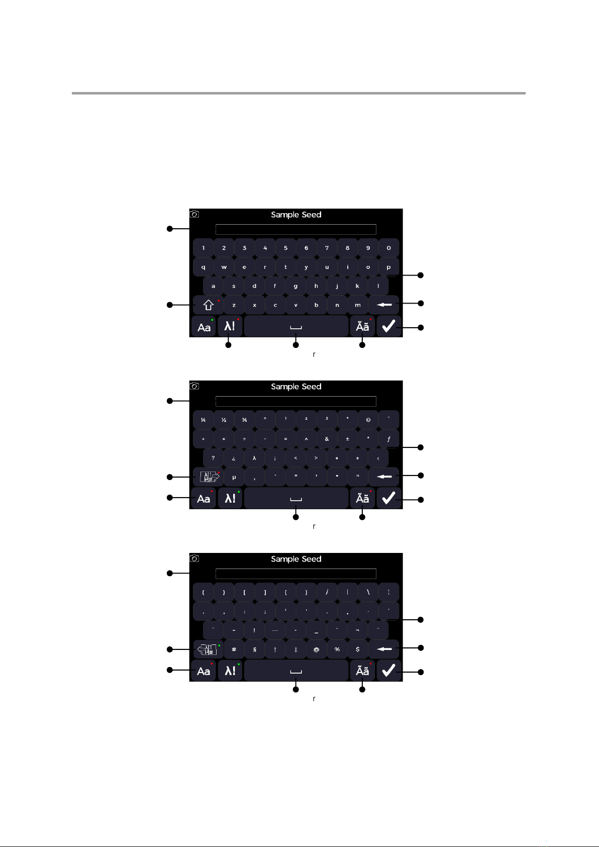
Onscreen Keyboards and Number Pad
“QWERTY” Alphanumeric Keyboard
Symbols Keyboard (page 1)
Symbols Keyboard (page 2)
Text Panel
Caps Lock
Confirm
Alphanumeric keys
Backspace
Spacebar
Symbol
Keyboard
Special Character
Keyboard
Text Panel
Page 2
“QWERTY”
Keyboard
Confirm
Symbol Keys
Backspace
Spacebar
Special Character
Keyboard
Text Panel
Page 1
“QWERTY”
Keyboard
Confirm
Symbol Keys
Backspace
Spacebar
Special Character
Keyboard
Ultrospec 7500 User Manual • 41 56 2050 REV03 •
15
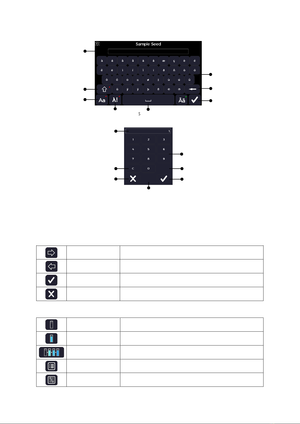
Special Character Keyboard
Number Pad
Frequently Used Icons
The frequently used icons detailed in this section are to support the quick-start operation of the instrument. Method specific icons are
detailed in the relevant method section.
Navigating Icons
Right/forward arrow
Progress to the next screen
Left/backward arrow
Return to the previous screen
Confirm
Confirm selection
Cancel
Cancel selection
Common Icons on the Sample Measurement Screen
Reference measurement
Take a reference measurement
Sample measurement
Take a sample measurement
Batch measurement
Take a batch measurement (with a cell changer)
Options
Open the options menu
Parameters
Return the method parameters
Text Panel
Caps Lock
“QWERTY”
Keyboard
Confirm
Special Character Keys
Backspace
Spacebar
Symbol
Keyboard
Number Panel
Clear
Cancel Confirm
Numeric Keys
Decimal Point
+ or -
Toggle Key

Ultrospec 7500 User Manual • 41 56 2050 REV03 •
16
Common Icons on the Options Menu
Exit
Exit the application and return to the application menu
Save data
Save the sample data
Save method
Save the method with the current parameter’s settings
Print
Print the sample data from the specified printer
Auto-print
Toggle auto print on (green) or off (red)
Go to std Curve
Takes you to standard curve screen
Load sample
Open saved sample data
Home Screen Toolbar Icons
Settings
Accesses the instrument settings
GLP Status
Open the GLP Application
Switch user
Open the user login window (only seen if ‘show log in’ is activated in user settings)
Information
Accesses the instrument information

Ultrospec 7500 User Manual • 41 56 2050 REV03 •
17
Instrument Firmware
The instrument firmware uses an intuitive menu arrangement that is navigated using the colour display icons and touchscreen.
First-time Start-Up
Upon first powering up of the instrument, the following screen sequence is displayed.
1: Self-calibration routine screen
2: Regional settings page. Select the appropriate settings
according to your location
3: Date and time setup page. Set the date and time according to
your location
4: Home page
After the first-time start-up, any future instrument starts-up will only display the self-calibration routine screen followed by the Home
page.
Home Screen
All applications can be accessed from the instrument Home screen using the icon-based menu. The Settings icon, the Switch User icon (if
enabled in the User Access Control Page) and the information icons are in the toolbar across the bottom. The pictures below represent the
different Home screen configurations possible.
Home screen for the Ultrospec 7500 spectrophotometer. No
user login has been set.
Home screen for the Ultrospec 7500 spectrophotometer
displaying the USB memory stick application and screenshot
camera icon, made available when a USB flash drive is inserted

Ultrospec 7500 User Manual • 41 56 2050 REV03 •
18
Home screen for the Ultrospec 7500 spectrophotometer when
User Login is available
Home screen for the Ultrospec 7500 spectrophotometer
displaying the USB memory stick application and screenshot
camera icon, made available when a USB flash drive is inserted
and User Login available
Login Screen
The instrument Ultrospec 7500 login screen is the first screen displayed after self-initialisation of the instrument if the ‘Show Login’ setting
has been enabled on the ‘Edit User Access –Parameters’ screen for the default Administrator user (see User Access section below for more
details). Once enabled, the unit can be unlocked using the switch user icon . Then with the user set to the default “Administrator”,
enter “1000” as the passcode and select the confirm icon. Confirm the user login details using the confirm icon to progress to the
instrument home screen.
Login screen for the Ultrospec 7500 spectrophotometer
User login window displayed after selecting the switch user icon
The pass code number pad displayed after selecting the pass code
entry box
The user login showing the default user login details

Ultrospec 7500 User Manual • 41 56 2050 REV03 •
19
Power Off
To Power off the instrument switch off the main switch to the off (0) position.
Main switch and 19 VDC power supply socket
Settings
The Settings screen is accessed from the home screen settings icon . The settings screen can be used to adjust the instrument
settings: date and time, regional, data output, user interface, accessories, user access, service and GLP settings. Note that the service
application is used by engineers and a passcode is required.
Date and Time
The Date and Time application is accessed from the Settings screen. It can be used to adjust the date and time stamp applied to measurement
data outputs.
There are several setting options available.
1. Set the day using the number pad.
2. Select the month from the selection menu.
3. Set the year using the number pad.
4. Set the hour (24-hour format) using the number pad.
5. Set the minute using the number pad.
Confirm any changes using the confirm icon.

Ultrospec 7500 User Manual • 41 56 2050 REV03 •
20
Regional
The Regional application is accessed from the Settings screen. It can be used to change the language and decimal separator number format.
There are several setting options available.
1. Select the language from the selection menu.
2. Toggle between full stop and comma number format decimal
separator.
3. Select the date format from the selection menu.
Confirm any changes using the confirm icon.
Data Output
The Data Output application is accessed from the Settings screen. It can be used to define the default printer and data output settings.
There are several setting options available.
1. Set auto print to “On” or “Off”.
2. If auto print is set to “On”, select the print to hardware from
“Internal Printer”, “PC via USB”, or “USB Mass Storage” depending
on what hardware is connected to the instrument.
3. Set auto save to “On” or “Off”.
4. If auto save is set to “On”, select the save to hardware from “USB
CSV”, “USB”, or “Internal” depending on what hardware is
connected to the instrument.
Confirm any changes using the confirm icon.
User Interface
The User Interface application is accessed from the Settings screen. It can be used to define the user interface preferences.
There are several setting options available.
1. Set the brightness from the selection menu on a scale of 0 to 8.
2. Toggle between “QWERTY” or “A to Z” keyboards for text entry.
3. Set the screensaver activation time from the selection menu, from
“Off”, “5 minutes”, “10 minutes”, “30 minutes”, or “1 hour”.
4. Toggle the parameter history to “On” or “Off”, to store application
parameters for future use or not.
5. Select the initial menu from the selection menu.
Confirm any changes using the confirm icon.
Table of contents
Other biochrom Measuring Instrument manuals

biochrom
biochrom NanoVue Plus User manual

biochrom
biochrom Ultrospec 3300 pro User manual

biochrom
biochrom Libra S35 PC User manual

biochrom
biochrom Novaspec III Plus User manual

biochrom
biochrom WPA Lightwave S2000 User manual

biochrom
biochrom Ultrospec 50 User manual

biochrom
biochrom Libra S6 User manual

biochrom
biochrom Libra S50 Instruction Manual

biochrom
biochrom WPA Lightwave 3 User manual

biochrom
biochrom Libra S21 User manual


