Biocontrol CL-10 Plus User manual

CL-10 Plus
User Manual

CL-10 Plus – User Manual 2 / 75 ECPUS vers 0.2 eng
Index
I
In
nd
de
ex
x_
__
__
__
__
__
__
__
__
__
__
__
__
__
__
__
__
__
__
__
__
__
__
__
__
__
__
__
__
__
__
__
__
__
__
__
__
__
__
__
__
__
__
__
__
__
__
__
__
__
__
__
__
__
__
__
__
__
__
__
__
__
__
__
__
__
__
__
__
__
__
__
__
__
__
__
__
__
__
__
__
__
__
__
__
__
_2
2
1
1.
.
I
In
nt
tr
ro
od
du
uc
ct
ti
io
on
n_
__
__
__
__
__
__
__
__
__
__
__
__
__
__
__
__
__
__
__
__
__
__
__
__
__
__
__
__
__
__
__
__
__
__
__
__
__
__
__
__
__
__
__
__
__
__
__
__
__
__
__
__
__
__
__
__
__
__
__
__
__
__
__
__
__
__
__
__
__
__
__
__
__
__
__
__
__
__
_4
4
2
2.
.
I
In
ns
st
ta
al
ll
la
at
ti
io
on
n_
__
__
__
__
__
__
__
__
__
__
__
__
__
__
__
__
__
__
__
__
__
__
__
__
__
__
__
__
__
__
__
__
__
__
__
__
__
__
__
__
__
__
__
__
__
__
__
__
__
__
__
__
__
__
__
__
__
__
__
__
__
__
__
__
__
__
__
__
__
__
__
__
__
__
__
__
__
__
_5
5
2.1 . Unpacking and checking. _______________________________________________________________5
2.2 . PC system Configuration._______________________________________________________________5
2.3. System Installation.____________________________________________________________________6
2.3.1
Installation Requirements._________________________________________________________6
2.3.2
Mains voltage setting. ____________________________________________________________6
2.3.3
Connection cables. _______________________________________________________________6
2.3.4
Software Installation and configuration______________________________________________7
2.3.5
Hydraulic connections. ____________________________________________________________9
2.3.6
Internal & peristaltic pump tubing’s _______________________________________________10
2.4.
CL-10 Plus switching on. _____________________________________________________________11
2.5.
Instrument Stabilisation._____________________________________________________________11
2.5.1
Materials.______________________________________________________________________11
2.5.2
Peristaltic starter tube sealing control._____________________________________________11
2.5.3
Electrodes regeneration. _________________________________________________________12
2.5.4
Standby mode (Rest)_____________________________________________________________12
2.6. Instrument stabilisation with wash solution_______________________________________________13
2.6.1
Instrument preparation (Milk application).__________________________________________13
2.6.2
Instrument preparation (Wine application). _________________________________________13
2.6.3
Starting and calibrating __________________________________________________________14
2.7.
End of working session. ______________________________________________________________14
2.8.
Changing of application within the same working session._________________________________15
3
3.
.
T
Th
he
e
I
In
ns
st
tr
ru
um
me
en
nt
t_
__
__
__
__
__
__
__
__
__
__
__
__
__
__
__
__
__
__
__
__
__
__
__
__
__
__
__
__
__
__
__
__
__
__
__
__
__
__
__
__
__
__
__
__
__
__
__
__
__
__
__
__
__
__
__
__
__
__
__
__
__
__
__
__
__
__
__
__
__
_1
16
6
3.1
The principle_______________________________________________________________________16
3.2
The Measuring System. ______________________________________________________________16
3.2.1
Instrument layout. ______________________________________________________________16
3.2.2
Titration curve and Buffer Power measurement. _____________________________________17
3.2.3
END POINT measurement. ________________________________________________________20
3.2.4
KINETIC measurement (KIN). ______________________________________________________26
3.2.5
FIXED TIME measurement. ________________________________________________________29
4
4.
.
T
Th
he
e
C
CL
L-
-1
10
0
P
Pl
lu
us
s
P
Pr
ro
og
gr
ra
am
m_
__
__
__
__
__
__
__
__
__
__
__
__
__
__
__
__
__
__
__
__
__
__
__
__
__
__
__
__
__
__
__
__
__
__
__
__
__
__
__
__
__
__
__
__
__
__
__
__
__
__
__
__
__
__
__
__
__
__
__
__
__
__
__
__
__
__
_3
32
2
4.1. Menu and commands. _________________________________________________________________32
4.2.
FILE Menu . ________________________________________________________________________34
4.2.1
Select method __________________________________________________________________34
4.2.2
Create a new method ____________________________________________________________35
4.2.3
Edit method____________________________________________________________________35
4.2.4
Add method for Measure unit change; Biochemical Chemistry Application________________39
4.2.5
Clear graph ____________________________________________________________________41
4.2.6
Print graph_____________________________________________________________________41
4.2.7
Method name___________________________________________________________________41
4.3.
START UP Menu . ___________________________________________________________________42
4.3.1
Prime Enzyme or F2._____________________________________________________________42
4.3.2
Clean or F3. ____________________________________________________________________43
4.3.3
START UP parameters. ___________________________________________________________43
4.3.4
Run Start up procedure or F4._____________________________________________________43
4.4.
ROUTINE Menu._____________________________________________________________________45
4.4.1
Sample (GO icon or F5). __________________________________________________________45
4.4.2
Blank (B icon or F6). _____________________________________________________________46
4.4.3
Calibrate (C icon or F7).__________________________________________________________46

CL-10 Plus – User Manual 3 / 75 ECPUS vers 0.2 eng
4.4.4
Stop Measure. __________________________________________________________________46
4.5.
WOKLIST Menu _____________________________________________________________________47
4.5.1
Print Worklist __________________________________________________________________47
4.5.2
Edit Worklist ___________________________________________________________________48
4.5.3
Erase Worklist __________________________________________________________________48
4.5.4
Export Worklist _________________________________________________________________48
4.6.
SERVICE Menu ._____________________________________________________________________51
4.6.1
Auto increment SAMPLE ID. _______________________________________________________51
4.6.2
Enter rest mode.________________________________________________________________51
4.6.3
Instrument parameters (Access password: default).___________________________________51
4.6.4
Calibrate Temperature. __________________________________________________________53
4.6.5
Communication parameters. ______________________________________________________53
4.6.6
Print Technical Report. __________________________________________________________53
4.6.7
Terminal Emulation _____________________________________________________________54
4.6.8
Electrodes Test 1 and 2.__________________________________________________________56
5
5.
.
M
Ma
ai
in
nt
te
en
na
an
nc
ce
e
a
an
nd
d
P
Pr
re
es
se
er
rv
va
at
ti
io
on
n_
__
__
__
__
__
__
__
__
__
__
__
__
__
__
__
__
__
__
__
__
__
__
__
__
__
__
__
__
__
__
__
__
__
__
__
__
__
__
__
__
__
__
__
__
__
__
__
__
__
__
__
__
__
__
__
__
__
__
__
__
__
_5
57
7
5.1
Weekly Maintenance_________________________________________________________________57
5.2
Routine Maintenance ________________________________________________________________57
5.3.
Maintenance – rapid guide____________________________________________________________58
5.4.
Enzyme Contamination in the reference electrode _______________________________________59
5.5
CL10 preparation for a period of halt (over 2 weeks). ____________________________________61
5.6
Instrument Reactivation _____________________________________________________________61
6
6.
.
T
Tr
ro
ou
ub
bl
le
e
S
Sh
ho
oo
ot
ti
in
ng
g.
._
__
__
__
__
__
__
__
__
__
__
__
__
__
__
__
__
__
__
__
__
__
__
__
__
__
__
__
__
__
__
__
__
__
__
__
__
__
__
__
__
__
__
__
__
__
__
__
__
__
__
__
__
__
__
__
__
__
__
__
__
__
__
__
__
__
__
__
__
__
__
__
_6
63
3
6.1.
Electrical Section. __________________________________________________________________63
6.1.1
Instrument does not switch on.____________________________________________________63
6.1.2
Pumps do not operate when the instrument is on.____________________________________63
6.1.3
The analytical unit does not accept commands from the program. ______________________64
6.2. Fluidic Section._______________________________________________________________________65
6.2.1
The Mixer does not fill-in or empty.________________________________________________65
6.2.2
Liquid spills out from the mixing chamber.__________________________________________65
6.2.3
Absence of signal during the measurement. _________________________________________66
6.2.4
Unstable Measurements ._________________________________________________________66
6.3
Electrodes. ________________________________________________________________________66
6.3.1
Control of electrodes performances________________________________________________66
6.3.2
Electrodes replacement. _________________________________________________________68
6.4.
CL-10 Plus troubleshooting – rapid guide________________________________________________71
7
7.
.
T
TH
HE
E
P
PI
IP
PE
ET
TT
TE
E,
,
c
ch
ha
ar
ra
ac
ct
te
er
ri
is
st
ti
ic
cs
s,
,
u
us
se
e
a
an
nd
d
m
ma
ai
in
nt
te
en
na
an
nc
ce
e.
._
__
__
__
__
__
__
__
__
__
__
__
__
__
__
__
__
__
__
__
__
__
__
__
__
__
__
__
__
__
__
__
__
__
__
__
__
__
__
__
__
__
__
_7
73
3
7.1
Materials. _________________________________________________________________________73
7.2
Using the Microman Pipette.__________________________________________________________73
7.2.1
How to Mount the Piston. ________________________________________________________73
7.2.2
How to mount the capillary. ______________________________________________________73
7.3
Pipetting.__________________________________________________________________________74
7.3.1
Aspiration._____________________________________________________________________74
7.3.2
Dispensing._____________________________________________________________________74
7.3.3
Simultaneous ejection of the piston and capillary. ___________________________________74
7.4
Pipette Specifications._______________________________________________________________74
7.5
How to Inject The Sample. ___________________________________________________________75

CL-10 Plus – User Manual 4 / 75 ECPUS vers 0.2 eng
CL-10 Plus
1. Introduction
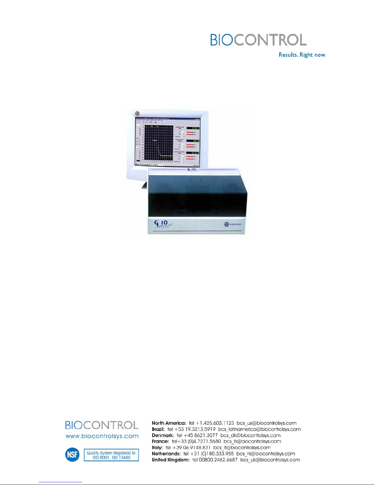
CL-10 Plus instrument is an automatic multi-parametric analyser, working in differential-pH
technique for chemical analyses in various type of matrices, from food industry to clinical
applications.
Technique characteristics are:
-Operative simplicity on different matrices, also particularly difficult ones.
-Versatility:
oexecutes the tests using few (from 5 to 1000) µL sample.
oin short time (from 15 seconds to 3 minutes).
-Promptness of response of tests made on unstable matrices.
-Use of dedicated and ready to use reagents, of 4-6 months shelf life
Products of common use are listed hereafter, in order to make the reading of the present
manual easier.
These products will be often mentioned, when required for routine procedures, maintenance
and repair.
Product Code Use
Polif Solution GEN718 wash solution, to be used with all Milk and Wine applications
Wash Kit GEN698 wash solution, to be used with all Clinical Chemistry applications, but not
with G6PD
Wash Kit GEN699 wash solution, to be used with G6PD Clinical Chemistry application
Diluent Buffer GEN644 to be used with Wine applications (when described in the specific
package insert)
Combi Clean GEN674 to be used with Wine Combi Test and pH/Acidity kits
Microman M25 micro-pipette GEN102 to be used with all applications, except Wine Combi Test and pH/Acidity
Electrodes test GEN603 Used to check electrodes performances, regardless the application field
(see§4.6.8)
Regenerating Solution GEN518 Used for the Maintenance §5
Strong Regenerating Solution GEN613 Used for the maintenance §5

CL-10 Plus – User Manual 5 / 75 ECPUS vers 0.2 eng
2. Installation
The CL10 Plus instrument consists of a thermo stable measuring block which contains two
capillary glass electrodes, a mixing chamber, two groups of peristaltic pumps, a differential
amplifier and a microprocessor which calculates the analyte concentration or enzyme activity
in the sample, and controls all the functions of the instrument.
CL-10 Plus is delivered with the fluidics empty (free from liquid) and dry and with the
peristaltic pumps unhooked (see § 5.5 figure; the detail of the pump tubing’s).
The procedure for the electrodes reactivation and stabilisation takes from 2 to 24 hours (see
§ 2.5.3).
2.1 . Unpacking and checking.
Check the list of content:
1. Instrument CL10 Plus
2. power 230 VAC (110 VAC) - 12 VDC
3. power cable
4. serial cable CL10-PC
5. Plastic bottles ( Kartel type) for the buffer and/or standby solution and for the waste
(2x250 ml)
6. Set pump tubing’s (Art. No. SSP112 or SPP112+SPP113)
7. CL-10 Plus Software on CD-ROM and relative Licence
8. CL-10 Plus Operator Manual
9. CL10 Plus Testing Certificate
Instrument Serial Number:
The serial number is located on the back of the instrument; it is the same number
written on the CL-10 Plus Testing Certificate .
2.2 . PC system Configuration.
•Pentium PC at 175 MHz or superior
•Microsoft Windows 95/98/2000/Me/XP
•RAM 32 MB or superior
•6 MB available on the Hard Disk
•floppy disk 3,5”
•Monitor Super VGA with 256 colours
•Video card with 800x 600 pixel
•CD-ROM 4x or superior
•COM1 RS232 9 pin or USB* port
•If USB port is used USB-RS232 converter is required.
(recommended: Targus Replicator type. PA070)

CL-10 Plus – User Manual 6 / 75 ECPUS vers 0.2 eng
2.3. System Installation.
2.3.1 Installation Requirements.
The CL10 Plus must be placed away from any vibration source (i.e. centrifuge),
magnetic field and intensive sun light.
It is recommended to maintain the room temperature between 15° and 30°C.
The power of the system (PC + instrument) must be connected to the ground (free
of noise). The power fluctuation must be secured < 5%. If not, it is recommended
to connect the CL-10 Plus instrument and the PC to a 500VA stabilizer. In any
case, it is recommended to keep the CL10 Plus instrument under UPS
(Uninterruptible Power Supply), for protection against accidental power loss.
2.3.2 Mains voltage setting.
The power converter is set for a range 100 - 230 VAC, automatically. For PC and
printer see producer manual.
2.3.3 Connection cables.
Connect the power to an available plug and to the CL10 PLUS (See picture 1).
Connect the CL10 Plus to the COM1 of the PC, using the serial cable.
Back vision of the instrument
PC + MONITOR
CL10 Plus PRINTER
POWER 12 VDC
VIDEO COM1 LPT1
POWER SUPPLY
SERIAL CABLE
LOCAL POWER SUPPLY POWER SUPPLY POWER SUPPLY
230 VAC 230 VAC 230 VAC
(110 VAC) (110 VAC) (110 VAC)
Fig. 1

CL-10 Plus – User Manual 7 / 75 ECPUS vers 0.2 eng
2.3.4 Software Installation and configuration
Materials:
-1 CD-ROM CL10Plus named as follows: U (sequential letter indicating the version)
CDROM_PLUS_05102004 (version release date) or superior.
Procedure .
To install the program on the PC, please follow the instructions:
1. Switch the PC and the Monitor on.
2. Insert the CD-ROM CL10Plus software in the CD-ROM unit.
3. From Explorer, open the CL10Plus vs. 4.3 CD-ROM or superior version.
4. Open the cl10plus vs 4.3 (or sup.) folder and select the Setup.exe icon.
5. Automatically, the program guided installation will start.
6. Follow the instructions on the screen.
7. Once the installation is completed, press OK. Remove the CD-ROM from CD unit.
8. Reboot the PC
For simplifying the access to the operative program: cl10plus.exe, it is recommended
to create a shortcut icon on the desktop
:
Point the mouse anywhere on the desktop
Press the mouse right-hand button and select: new link.
Once the new window appears, search for the following path: C:\cl10\
cl10plus
Select Next, and then End.

CL-10 Plus – User Manual 8 / 75 ECPUS vers 0.2 eng
Set up of the software
1. Access to the software icon, on the desktop: cl10plus
2. The following message appears
;
select OK.
3. From Service window in the main menu of CL10Plus program, select Auto increment
sample ID to activate the function of start measure by pushing the Enter key of the PC
board.
4. Access again to the Service window, select Enter password and type: “default”
5. Access once more to Service, select Instrument parameters
6. In the top left square of the window, select Mixer volume : high
7. In the bottom right square of the same window select Activate rest mode in order to
set the rest mode interval between cycles= Period (min) at 120 seconds and the
temperature= temp (°C) at 37°C.
8. Press OK.
Methods setting
9. Check that the CL10Plus CD-ROM is in the CD unit.
10.Open the following folder D:\ CD-ROM\ S_Plus_Matrix Name_XXX\CL10Plus vs.4.3.
11.Open the folder containing the name of the application field (Wine or Milk or Bio).
There is a letter (example: S) before the field of application. This letter is containing all
the information concerning the version number of all methods contained in the CD
ROM .
12. From this folder open the next folder called English; There are three more folders
inside: Methods_MD, Service_TBL, Tables_TBL
13.Service_TBL, Tables_TBL are not used by the operator, but only by service
personnel. Open the Methods_MD folder.
14.Copy all the files contained, do not open them! Paste these files in the following
folder: C:\cl10.
15.Change properties of the pasted files; from read only into archive.
16.Unable the screen saver and the energy save setting, in order to avoid any
interference during the working session.

CL-10 Plus – User Manual 9 / 75 ECPUS vers 0.2 eng
2.3.5 Hydraulic connections.
1. Hook the peristaltic tubes with lower diameter in position 6 (and 5, if required by the
method), without twisting them.
Warning: if tubing’s are twisted, analytical reliability is compromised. To be able to verify the correct tubing’s
assessment, mark the thick ends of each tube before hooking it, on the same side along the fusion line and
check that, once hooked, it remains marked on the same side.
2. Hook the 4 peristaltic tubes, with higher diameter, in position 1,2,3 and 4 without
twisting them. Careful that the ’L’ connections are not pushed to the far end of the
silicon but only halfway.
3. Place the bottle in the waste position.
4
5
6
1
2
3
TAMPONE/BUFFER
SCARICO/WASTE
ENZIMI/STARTER
7 8
9
Fig. 2

CL-10 Plus – User Manual 10 / 75 ECPUS vers 0.2 eng
2.3.6 Internal & peristaltic pump tubing’s
Internal tubing’s are 8 pcs (SPP311); normally they are not considered as
consumables, unless accidentally broken or damaged.
Peristaltic tubing’s, or pump tubing’s, are consumables and as such, they must be
checked before installation and inspected every three months.
It is recommended the replacement every 3000 cycles, that means in average,
3-5 months of work.
Description of tubing types, and destination:
Pos Description & Packaging
Code
1 Internal Tubing’s set 8x SPP 311
2 Peristaltic Pump Tubing’s Set 4x SPP 312
3 Enzyme Starter tubing only mono starter 1x SPP 313
4 Additional Tubing: sample+starter Wine Combi 1+1 SPP 314
5 Additional Tubing: sample +specific Wine pH/Acidity 1+1 SPP 315
6 Additional Tubing’s: double starter Bio G6PD/6PGD 1+1 SPP 316
SPP 311 : product for all configurations and all applications
SPP 312: product for all configurations and all applications
(pump tubing’s 1-2-3-4, Fig 2 § 2.3.5)
SPP 313: product for all kits other than WCP678-682, BCP 592-596-690 (pump
tubing 6, Fig 2 § 2.3.5)
SPP 314: product for WCP678, only (pump tubing’s 5-6, Fig 2 § 2.3.5)
SPP 315: product for WCP682, only (pump tubing’s 5-6, Fig 2 § 2.3.5)
SPP 316: product for BCP 592-596-690, only
(pump tubing’s 5-6, Fig 2 § 2.3.5)

CL-10 Plus – User Manual 11 / 75 ECPUS vers 0.2 eng
2.4. CL-10 Plus switching on.
Make sure that all the power supply and serial cable are properly connected.
Switch the CL10 Plus on, from the switch placed in the back panel of the
instrument.
On(up)
Off (down)
If the light under the instrument lead, in the front panel, does not turn on (green),
check all the connections again and the power supply.
2.5. Instrument Stabilisation.
2.5.1 Materials.
EC Polif kit.
Distilled water
2.5.2 Peristaltic starter tube sealing control.
Place (Fig. 2, §6.3.1) a vial containing at least 2 mL distilled water in starter
position and place the needle of the starter tube inside the vial.
Run Prime enzyme cycle to fill-in the starter tube.
Take both ends of the starter tubing (completely filled-in with water) from the vial
and lift in the air the opposite end to the needle: if the peristaltic starter tube has a
good seal, the level of the water should not move.
If the level of the water inside the starter tube comes back, the tubing must be
replaced.
When the starter tubing is correctly filled in with water, connect the tube end to the
steel capillary on the mixing chamber stopper.
Warning: the connection of the starter tubing to the top of the mixing chamber is a critical step.
It is very important to connect it gently, taking care to the final position of the yellow ring embracing firmly the
silicon of the starter tubing and the steel capillary on top of the mixing chamber.

CL-10 Plus – User Manual 12 / 75 ECPUS vers 0.2 eng
2.5.3 Electrodes regeneration.
NOTE: Regenerating procedure of measuring electrodes is used to reactivate the instrument after a period of
halt (installation or after a period of rest); electrodes, after this procedure require a “stabilization” time; it is
therefore recommended to operate the Rest Mode procedure immediately after, using wash solution as a buffer.
Electrodes regenerating procedure:
1.
Reconstitute the wash solution, according to the instructions given in the kit.
2.
Place the reconstituted solution in buffer position and an empty bottle in waste position
(Fig. 2, § 2.3.5).
3.
Run 3 Clean cycles.
4.
Replace the bottle containing wash solution with a bottle of Regenerating Solution in
buffer position.
5.
Run 3 Clean cycles.
6.
Wait for 5 minutes.
7.
Replace the Regenerating Solution with a bottle of distilled water and run 2 Clean
cycles.
8.
Replace the bottle of distilled water with reconstituted wash solution, again and run 3
Clean cycles.
9.
Empty the waste bottle.
2.5.4 Standby mode (Rest)
For the CL-10 Plus instrument there are two available different standby mode
(REST mode):
1 From the computer, REST mode program ( § 2.3.4).
From Service window enter Enter Rest Mode command
Switch the monitor off
Leave the PC on
Leave the CL-10 Plus instrument on
ATTENTION: Check if there is enough Wash Solution for all the standby period (the washing cycle automatically
runs every 120 minutes and consumes from 4 to 9 mL of wash solution each cycle, depending on the execution
method selected).
2 From the instrument, REST mode: the instrument stays at 37°C and the time laps
between consecutive clean cycles is 90 minutes.
Switch the PC monitor off.
Switch the CL10 Plus off.
Allow 5 seconds, then switch the CL10 Plus on again.
The instrument runs 1 clean cycle every 90 minutes at 37°C.
ATTENTION: Check if there is enough Wash Solution for all the standby period (the washing cycle automatically
runs every 90 minutes and consumes from 4 to 9 mL of wash solution each cycle).
ALLOW STANDBY OVERNIGHT, at least; it is not required for 2-3 hours interruption of working session

CL-10 Plus – User Manual 13 / 75 ECPUS vers 0.2 eng
2.6. Instrument stabilisation with wash solution
1. Use reconstituted wash solution and place in buffer position.
2. Empty the waste bottle
3. Enter CL10 Plus program, from File menu select (using Select method command)
the execution method (the instrument will automatically set the desired
measurement block temperature).
4. Unplug the starter needle (connected to pump 6) from the top of the mixing
chamber and place both ends in a vial containing distilled water.
5. Run 1 Clean cycle and wait for temperature stabilisation (the yellow led in the front
panel of the instrument will decrease its intensity and turn almost off).
6. Run Start Up procedure setting 5 measure cycles (§ 4.3).
7. The instrument is stable and ready to work when three consecutive measurements
have ∆mpH < ±0.5 mpH, and the D1 of the last two measurements do not differ
more than 1 mpH from each other.
2.6.1 Instrument preparation (Milk application).
The following procedure (taken as an example) applies to UREA in milk (Art.
No. MCP549).
Replace the reconstituted wash solution with R1 buffer.
Check that the enzyme tubing (connected to pump 6) is plugged to the top of the
mixing chamber.
Follow the instructions on the Package Insert of EC Milk Urea.
2.6.2 Instrument preparation (Wine application).
The following procedure (taken as an example) applies to EC Wine COMBI
test : pH, total acidity, glucose + fructose (Art. No. WCP678).
Replace the reconstituted wash solution with R1 buffer, reconstituted according to
the package insert of the kit.
Check that the enzyme tubing (connected to pump 6) is plugged to the top of the
mixing chamber.
Check that the AUX tubing, the longer (connected to pump 5), is plugged to the top
of the mixing chamber, too.
Follow the instructions on the Package Insert of EC Wine COMBI test.
.

CL-10 Plus – User Manual 14 / 75 ECPUS vers 0.2 eng
2.6.3 Starting and calibrating
ATTENTION: Carry out the following measurements in a sequence. If you wait more than 5 minutes between
two consecutive measurements, run GO command, without injecting any sample, to renew the buffer in the
mixing chamber.
Equilibrate samples at room temperature before testing. Samples must be
homogeneous when assayed.
Run GO cycle or press F5 function key (without injecting any sample).
Repeat the GO cycle and check the stability (according to the package insert in the
kit).
a) Offset determination: Execute Blank cycle (F6) once. The blank value must be
in the range of the method package insert.
b) Calibration: inject Calibrator using the Gilson Microman M25 pipette or trough
the AUX tubing (according to the package insert) and run Calibrate cycle (F7)
once. If the SLOPE value obtained is OUT OF RANGE, the result will appear in
red (see package insert and § 4.4.3 of this manual); in that case repeat points a)
and b).
Blank check: run GO command (F5) without injecting any sample. The result has
to be included between 0 ±allowance claimed in the package insert.
Standard check: inject Calibrator with the Gilson M25 pipette or trough the AUX
tubing (according to the package insert) and run GO command. The result must be
within the range expected for the calibrator, from the method package insert ±
allowance claimed.
2.7. End of working session.
At the end of the working session replace R1 buffer with the reconstituted
Wash Solution.
Replace starter vial (and AUX if used) with a vial containing distilled water
(min 3 mL).
Run 2 Prime enzyme (F2) and 2 Clean cycles (F3).
Empty the waste bottle.
Leave the instrument in standby condition or Rest mode.

CL-10 Plus – User Manual 15 / 75 ECPUS vers 0.2 eng
2.8. Changing of application within the same working session.
ATTENTION: Steps 2 and 3 of the following procedure allow recovery of not utilized enzyme, still inside the
starter tube (position 6). If the enzyme vial is empty or all the tests are made, it is not necessary to recover the
enzyme; it is therefore recommended to neglect steps 2 - 3 and to go from step 1 to 4.
1. Replace R1 buffer, reconstituted as required by the method in use, with the R1 buffer,
reconstituted as required by the next method. Leave the enzyme vial (pump 6) of the
method in use in its place.
2. From File menu, Select the ENZY_REC_R3 method.
3. Run Sample once using the GO icon or the F5 function key. Press Start Measure and
Accept. Wait until the end of the run.
4. Replace the enzyme vial (pump 6) with a vial containing distilled water.
5. Run Prime Enzyme twice using the prime enzyme icon or the F2 function key.
6. Run Clean once using the clean icon or the F3 function key.
7. Wipe the starter needle going to enzyme pump 6 and insert it into the enzyme vial
(starter) of the next chosen method.
8. From File menu, Select the next method.
9. Empty the waste bottle.
10. Follow the instructions given in the package insert of the method to use.

CL-10 Plus – User Manual 16 / 75 ECPUS vers 0.2 eng
3. The Instrument
3.1 The principle
The differential pH technique is based on the correlation of pH variations, which are
measured by two capillary glass electrodes, to the quantity of H
+
produced or consumed by
a reaction, which is started by adding the necessary enzyme or substrate.
3.2 The Measuring System.
The CL10 Plus is a compact and easy to operate instrument. It is made of a differential
amplifier and a microprocessor which calculates the analyte concentration or enzyme
activity in the sample, and controls all the functions of the instrument.
The mechanical components are:
3.2.1 Instrument layout.
n°1: pump of the Electrode 1
n°2: pump of the Electrode 2
n°3: level pump
n°4: pump of the buffer
n°5: starter pump (AUX)
n°6: starter pump
n°7: electrode 1
n°8: electrode 2
n°9: mixing chamber
4
5
6
1
2
3
TAMPONE/BUFFE
R
SCARICO/WASTE
ENZIMI/STARTER
7 8
9
Figure 2 § 2.3.5:

CL-10 Plus – User Manual 17 / 75 ECPUS vers 0.2 eng
3.2.2 Titration curve and Buffer Power measurement.
•Titration curve.
Titration is used to determine the amount of acid in a given solution. In this procedure a
measured volume of sample is titrated with a solution of a base, usually sodium
hydroxide (NaOH), the concentration of which is known. The NaOH is added in a small
increments until the acid is neutralised, as determined with an indicator or a pH meter.
From the volume of NaOH added at known concentration, it is calculated the
concentration of acid in the solution titrated.
From the titration of a sample containing weak acids (pK between 3 and 6) additional
information are obtained, measuring the pH of the acid after each increment of NaOH
added, to the point of neutralisation. A plot of pH of the solution vs. the amount of NaOH
added to this point is called ‘titration curve’.
Let us take the titration curve of acetic acid, a typical weak acid. At the beginning, (see
figure) before any NaOH is added, the acetic acid is slightly ionised.
When aliquots of NaOH are added, the added OH
-
will combine with free H
+
in the
solution to form H
2
O. As soon as free H
+
is removed, some of undissociated acetic acid
immediately dissociates. At the midpoint of the titration, one-half of the original acetic
acid has undergone dissociation, so that the proton-donor concentration will be equal to
the proton-acceptor concentration.
As the titration is continued by adding further increments of NaOH, the remaining
undissociated acetic acid is gradually converted into acetate.
The titration curve is a reversible reaction (adding H
+
back to the system, acetate is
converted back to the initial state).
NaOH added
pH
7
pK of
Acetic Acid
3

CL-10 Plus – User Manual 18 / 75 ECPUS vers 0.2 eng
•The Buffer Power.
Buffer is an aqueous system that tend to resist to pH changes, once small amount of
acid (H
+
) or base (OH
-
) are added.
A buffer system consists of a weak acid (proton donor) and its conjugate base (proton
acceptor), as for example the acetic acid form and acetate form.
The “Buffer Capacity” is defined as:
∆H
+
(H
+
concentration)
β
= ------------ = --------------------------
∆pH (pH variation)
in which the ∆pH is the pH increment induced by the addition of an amount of base,
whereas ∆H
+
is the relative change of free H
+
in solution. A large “Buffer Capacity” of
the medium corresponds to a large amount of base required to achieve a small change
in pH.
BUFFER POWER measurement, using CL-10 Plus instrument.
The working buffer, using CL-10 Plus, must provide a known and constant Buffer Power.
Sensitivity of the method depends on sample volume, stoichiometry and Buffer Power.
Sample: HCL 100 mM
Buffer Solution: Total Acidity
Stopper: volume of 1225 µL
Temperature: 37°C
Micropipette: Gilson Microman M25
Sample Volume: 10 µL

CL-10 Plus – User Manual 19 / 75 ECPUS vers 0.2 eng
PROCEDURE
∗From the File menu, enter Edit command and select the BETA800_R2.MD method.
Check the parameters (see the following window). If the settings are not the same or
the method is not found, contact technical assistance.
∗Once the settings are controlled, press Esc on your keyboard and from File menu, enter
Select method command. Choose the same method and wait until it is visualised on the
screen
∗Inject sample (10 µL of HCl 100 mM) in the mixing chamber
∗Run Sample command or press the GO icon or the F5 function key. Press Start Measure,
then Accept.
Principle.
Step 1: both the electrodes and the mixer are filled with the buffer solution.
Step 2: after 3 seconds (wait time) a sufficient amount of buffer + sample is aspirated into
electrode 2. The buffer solution is maintained in the electrode 1. The pH change due to
HCL acidification is instantaneous. 15 seconds are allowed to electrodes stabilisation, then
the result is displayed on the screen.

CL-10 Plus – User Manual 20 / 75 ECPUS vers 0.2 eng
Calculation (taken an hypothetical result of 185 mpH).
Dilution: 10 µL of HCL 100 mM are injected into 1225 µL of buffer, the dilution is 1:123. The
∆H
+
in the mixer is calculated as follows:
sample volume 10
∆H
+
= sample acid concentration x ------------------------- = 100 x -------- ≈0.81 mM
final volume 1235
Buffer Power calculation:
∆H
+
(concentration) 0.81 mM/L
β
= ------------ = -------------------------- = ------------------- = 4.38 mM/L pH
∆pH (pH variation) 0.185 pH
3.2.3 END POINT measurement.
A practical example: urea determination in milk.
The heart of the differential-pH apparatus are the mixing chamber and the two electrodes:
electr. 1
electr. 2
starter 1
stirrer
Sample
E -E
21
D 0
Analysis of the steps of measurement:
PHASE ZERO: the mixing chamber and the electrodes are filled with buffer, ready to accept
the sample.
PHASE 1: using the micropipette, inject 25 µL of milk in the mixing chamber; the stirrer
rotates and mixes buffer + milk for some seconds.
Table of contents
Other Biocontrol Medical Equipment manuals