BioMedix Configured Olympus CX43 User manual

Page 1 v3.01.22
Quick Set-up Guide for the Biomedx Configured Olympus CX43

Page 2 v3.01.22
Your microscope is supplied with an Olympus CX43 Manual, please refer to that
for more complete information on microscope operation. This guide is meant to
give you a quick overview of the system setup and the camera operation with
pertinent specimen viewing tips.
ON-LINE REVIEW FILES
Quick video review of this microscope’s operation.
https://media.biomedx.com/sitevids/using-microscope.mp4
Review pages on getting a sample slide specimen and viewing with the scope.
https://media.biomedx.com/sitedocs/microscope-specimen-observation.pdf
Other Videos/Files
https://biomedx.com/support
https://youtube.com/biomedx
>>> STEPS FOR MICROSCOPE ASSEMBLY <<<
When you get your microscope you will find that the various parts are packed in
different boxes. You will find it advantageous to take everything out of the boxes and
lay them on a clean work surface so you can then begin the identification process and
assembly.
Depending on your chosen configuration, you may have parts and pieces that differ
somewhat from what is shown here. You may have some components and not others
though in all respects the basic nature of the assembly of parts does not differ.
Sign up to the Biomedx Newsletter to keep informed on
events, classes, online programs, new hardware, scope
scoops, etc. at biomedx.com
Enroll at edu.biomedx.com to access
educational modules covering microscopy
of living blood, dry layers, gingival material,
urine, plus flow auditing and more.

Page 3 v3.01.22
Assembly Steps
Setting up Your System 4
Mounting the Trinocular Port 5
Putting on the Camera Assembly 6
Parfocal Monitor/Eyepiece Adjustment 6
Putting on the View Head and Eyepieces 7
Plugging in the Camera 8
WiFi 8
Power 9
Video Only Setup 10
Operation Notes
Modes of the Condenser 11
Specimen Stage, X-Y Control, Phase Adjusters 12
Focus Knobs, Tension Adjustment, Stage Stopper 13
HD Camera 14
HDTV Setup 17
Condenser Mode Viewing Tips 19
Using Oil Objectives 20
Supply Reorder, Workshops, Support 23
Page 4 v3.01.22
Trinocular
Camera Port
Assembly
Allen Wrench
Holder
Stage/condenser Lock Tool
(You will not be using this.)
Eyepiece
Clamping
Screws
Eyepiece
Oculars
Binocular
View Head
HD Camera, pre-attached
to scope video coupling
lens. (Power supply not
shown.)
Camera software
WIFI USB
Adapter
Camera
Mouse
Microscope base frame w/ integrated
stage, multi-mode condenser, LED lamp.
Objectives pre-installed.
Video HDMI
connector cord
AC Power Cord
AC Adapter
Assembly Allen
Wrench
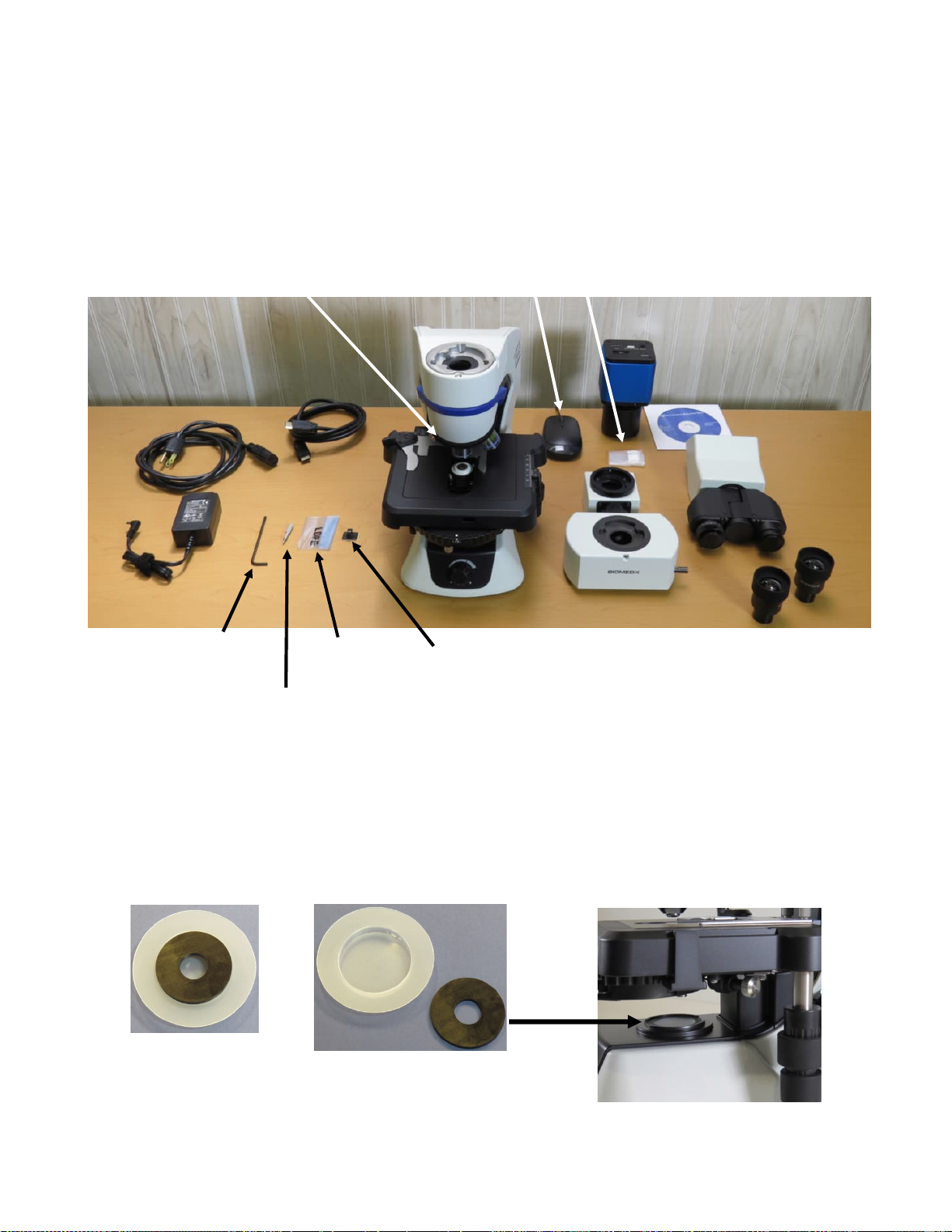
Setting up Your System - Begin by laying everything out on your workspace.
When you do, you will see something like the picture below differing only in the
items that were selected in your particular configuration. Biomedx pre-assembles,
pre-checks and pre-adjusts everything prior to shipping so the objectives will
already be mounted in place.
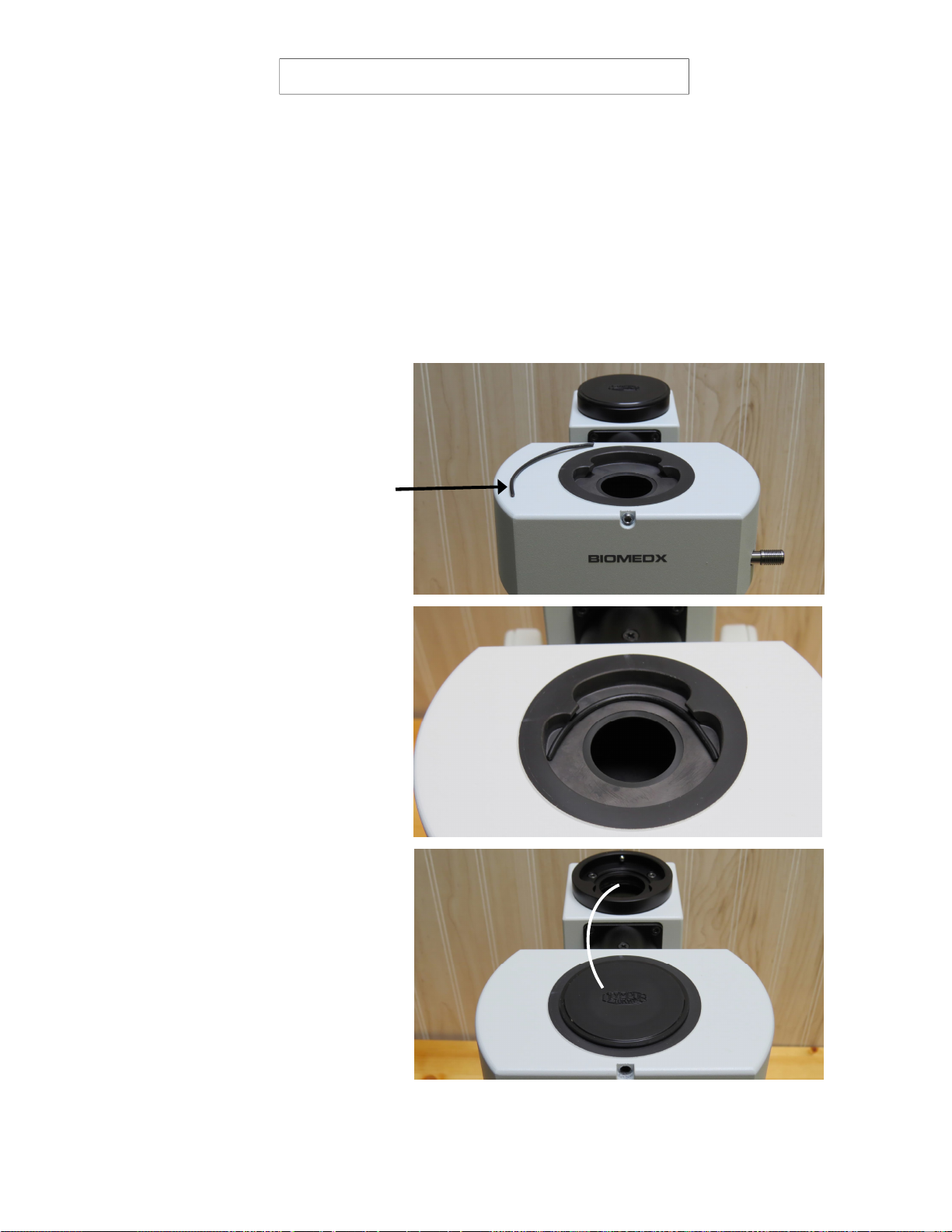
Disc removedfrom cover. Place
onto filter space shown to enhance
darkfieldviewinturretDFmode.
When your scope shipped there was a top cover over the objective tube opening on the very top of
the microscope. It is not shown on the scope in the above picture but shown below. Fitted inside the
plastic cover is a black plastic donut. This is a darkfield enhancer. When the microscope is being
used in darkfield mode (up to 40x*), this donut can be slipped above the light lens at the base of the
scope. This will enhance darkfield imaging by taking out some of the scattered light which tends to
lighten a darkfield background. You can leave it there for phase contrast & 3D views as it will not
affect the image, but It must be removed for brightfield.
Scope top-hole
cover with dark-
field donut/disc.
Not shown: plasc dust covers & item(s) below.
* If a 50x or 100x oil iris objecve for darkfield is on your scope, you will have received a variable iris as well which
needs to be used in place of the fixed disc shown here and adjusted as needed in conjuncon with the objecve’s iris.
Page 5 v3.01.22
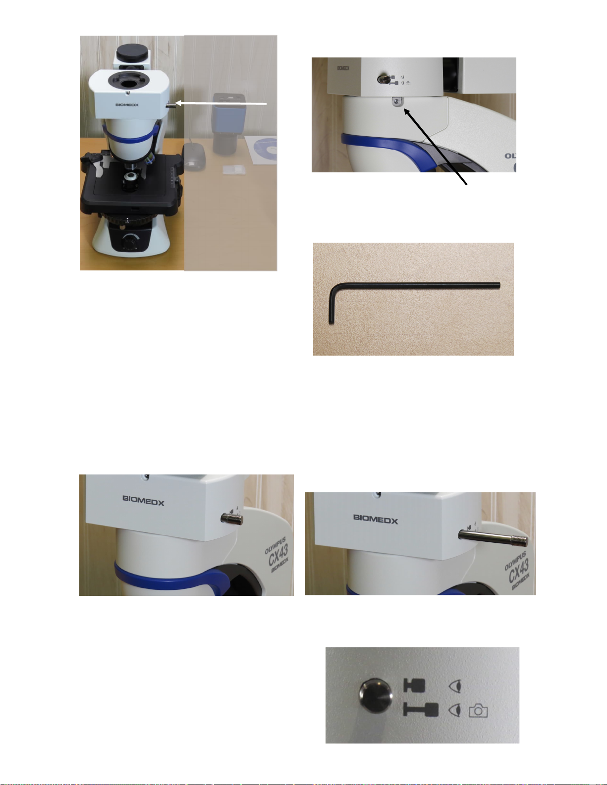
Mount the
Trinocular
Camera Port
Assembly
Use the Allen wrench to loosen
the set screw a bit then mount the
assembly and tighten.
Note: There is a slider bar on this assembly. This slider moves an internal prism
back and forth. When the slider is pushed in, 100% of the light is directed to the
eyepieces. When pulled out, 20% of the light remains in the eyepieces and 80% is
directed to the video camera.
To see an image on your camera’s TV,
the slider must be pulled OUT.
If the bar is only pulled half way out, you will
only see half an image on your monitor.

Page 6 v3.01.22
Mount the
Camera
The set screw to
hold the camera
assembly in place
points to the back
on the port itself.
The video camera is pre-mounted on a
microscope optical coupling lens.
You will note two set screws, marked
FOCUS and LOCK.
This is for parfocal adjustment. These
are preset before shipping.
Parfocal means when you have a focus
on your microscope (as viewed through
the right eyepiece ocular) your video
image will also be focused.
If your monitor is not in focus with your
right eyepiece scope view, you can
correct the video focus by loosening the
lock screw, adjusting the focus screw
which will focus the video on the monitor,
and then re-tightening the lock screw to
hold it in place.
Page 7 v3.01.22
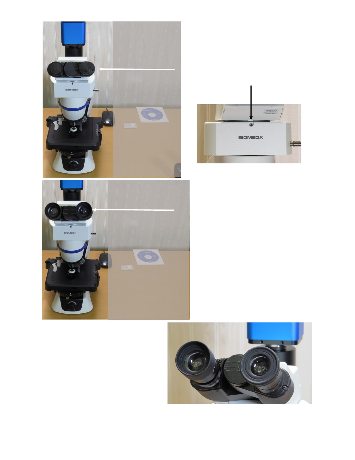
Mount the
Binocular
Eyepiece Head
(See page 10 for video only setup using no
binocular vew head or eyepeices.)
Remove the lens
caps from the
binocular head and
install the 10X FN 20
eyepiece oculars
with rubber eyecups.
Note that the oculars just slide right
down into the hole.
If desired you can screw the supplied
clamping screws into the tiny screw
holes on the ocular barrel to hold
them in place.
The rubber eyecups can be unfolded
for normal viewing as shown here on
the left eyepiece or folded down as
shown on the right eyepiece when
wearing glasses.
The eyepiece tube assembly can be
pulled apart as well as tilted to adjust
for your own eyes.
The left eyepiece tube has a diopter adjustment. In use, you would focus the
microscope viewing the right eye first, then adjust the diopter to focus the left.
The set screw to hold the head in place
is directly in front and below the head.

Page 8 v3.01.22
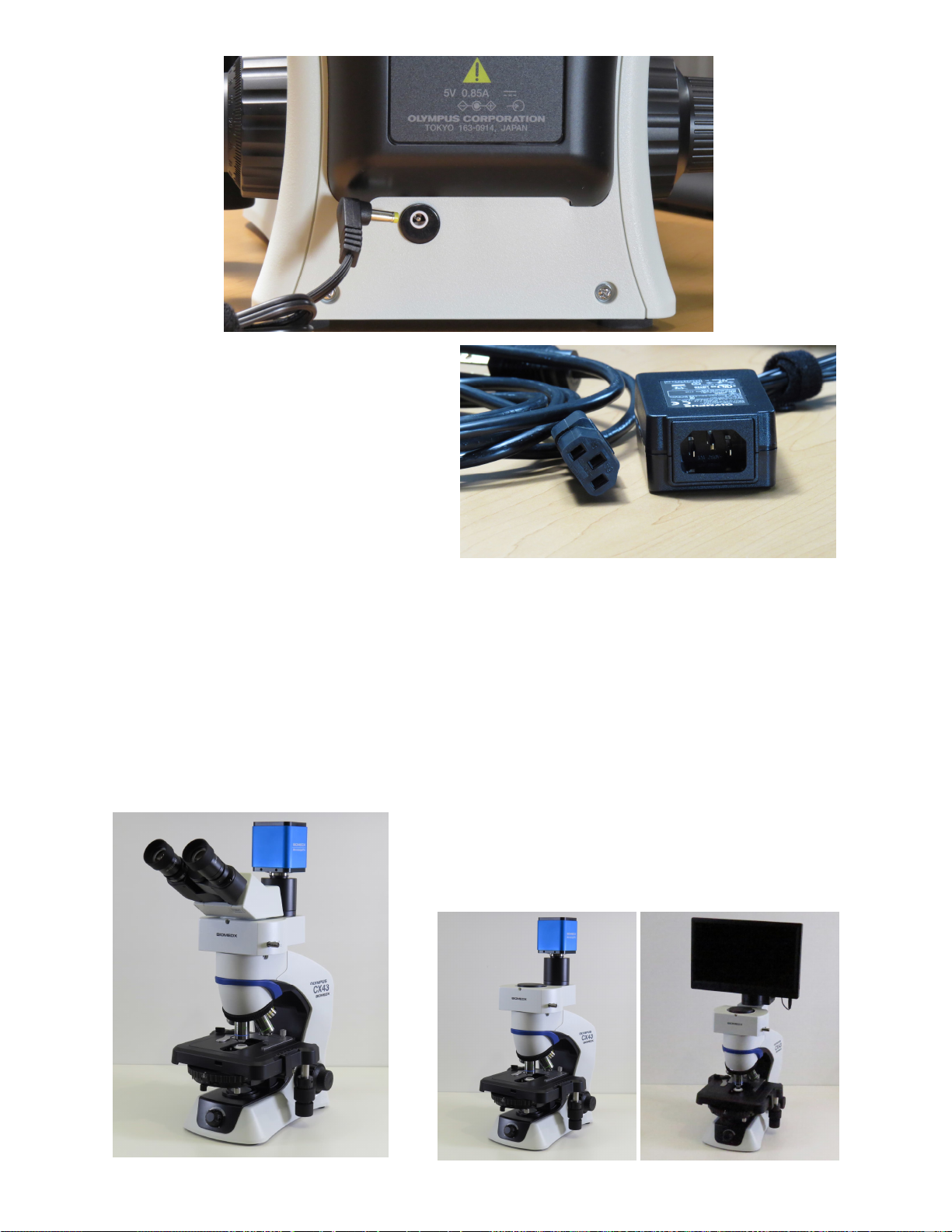
Plug in the AC adapter for the
camera to DC12V.
Plug the mouse into the USB
port.
Plug one end of the HDMI cable
into the camera slot marked HDMI
and the other end into your HDTV
HDMI input.
The HDMI cable will have
ends as shown here.
NOTE: Computer HDMI
slots are OUTPUT slots for
monitors and NOT input slots
for cameras. DO NOT plug
your camera HDMI cable
into a computer HDMI slot.
Example of a HDTV input.
The best imaging will be on a HDTV
with 1920 x 1080 resolution.
To use a computer/laptop for image save/capture/record: Plug the WIFI chip into
the camera’s WiFi/USB socket. Turn on the camera and go to your computer’s WIFI
settings to view available networks. Find BIOMEDXCAM and connect using password
12345678. The camera will now be able to be found via the camera’s software (which
must also be installed on the computer/laptop.)
Here is a 24”
HDTV on a desk
stand to raise it
off the desk. Up
to 32” size can
be mounted in
this fashion.
Page 9 v3.01.22
As a last step to set up,
plug the AC power
adapter into the back of
your microscope.
You will note a Velcro strap on the power
cord, you can use this and other Velcro
straps to tidy up the cords behind the
microscope and from the camera.
It’s always a good idea to plug your system into a surge protected AC power
strip. When you are not using your system you can simply switch off the power
strip. In addition, when not using your microscope, you can put a cover on it to
keep the dust off. When using a plastic cover, just pop it over the whole scope
leaving some room for air to get in the bottom so you don’t lock in any moisture.
Assembled system.
Video only system & with a view screen.
Page 10 v3.01.22
NOTE FOR VIDEO ONLY SCOPE
If you purchased a “Video Only” microscope, this page should be reviewed in lieu
of page 7 of this quick set-up guide which shows you the trinocular video port set
up for a video only scope. The steps shown here may have already been done
prior to the scopes shipment to you. If it has not been done, do the setup
procedure below.
(If you have a binocular port with eyepieces and desire to temporarily ‘travel light’
without that assemby, you can obtain a short 14-16 gauge wire as shown and
you can swap the binocular head with the cameral port cover cap through this
procedure.)
Packaged with your trinocular
port is a short wire.
Place this wire into the
binocular head receptacle
slot as shown here.
Move the camera port cover
cap from the back to the front
and lightly tighten the set
screw in front to center the cap
and keep it in place.
Should you get a binocular view head with eyepieces in the future, you would simple
remove this cap and wire and mount the head as shown on page 6 of this set-up guide.

Page 11 v3.01.22
OPERATION NOTES
Your microscope has a factory built-in
multi-mode universal turret condenser.
By simply rotating the condenser turret
left or right, you can change the
condenser mode from brightfield to
darkfield to phase contrast and even to
a 3D image perspective.
Condenser Modes
DF—
PH3—
PH2—
PH1—
BF—
2X—
FL —
Darkfield
Phase Contrast using 60x and 100x oil phase objectives.
Phase Contrast using a 40x phase objective
Phase Contrast using a 10x or 20x phase objective
Brightfield (note that this setting has an associated condenser
iris adjuster and set-screw to set image contrast/depth of field).
Generally for live blood viewing you would close the iris quite a
bit to give you more contrast and depth of field, and open it up
for a dry blood view to give you less contrast and depth of field
This is when using the 2X plan objective so you can see a wider
field of view when looking into the eyepieces.
This is for reflected light fluorescence viewing (Scope as shipped
is not equipped for fluorescence.)
The most popular Biomedx configuration is set up for non-oil microscopy using all
condenser modes and will have 2x, 4x, 10x, 20x, 40x objectives. The 2, 4 & 10x optics
are typically used for brightfield viewing (the 10x will give a very wide field darkfield
view) The 20x is a phase objective and you will find PH1 indicated on the lens barrel
telling you to use the PH1 setting on the turret. You can also use DF. The 40x is a
phase contrast objective and an everyday working optic for live cell work. It uses the
PH2 turret setting for phase contrast, DF will provide darkfield, and if you slightly shift
the turret out of the DF indent position, you will have a 3D view of your sample.

Page 12 v3.01.22
The top condenser
lens can be oiled IF
you were using an oil
objective.
The lens can be
pulled forward an inch
to drop on the oil and
for cleaning.
Microscope Stage
X-Y slide control
Phase Contrast
adjusting knobs are
found on both sides
of the scope.***
*** IMPORTANT NOTE These knobs are essentially screw drivers on a spring. If
you were in the PH1, PH2, or PH3 mode on the condenser and pressed in on these
knobs and then rotated them, you would move the pre-adjusted phase annulus of
the condenser and push it out of adjustment. DO NOT do that unless you know what
you are doing and have a phase centering telescope and can put the annulus back
where it belongs. See the manual and review videos on-line for reference.
The phase contrast adjustments were pre-set for the phase objectives on your
microscope prior to shipping and once set about the only way they can be un-set is
to inadvertently or directly push in and rotate these knobs. Ergo, DO NOT push in
and rotate or fiddle with these knobs because you could put your phase imaging and
clarity out of whack.

Page 13 v3.01.22
Focus knob: Raises
and lowers the stage.
Large outer knob is
course focus, inner
smaller knob is fine
focus.
On/Off Switch Light intensity dial: Typically
turned down for brighfield lighting,
about 12 o’clock to 3 o’clock range
for phase, 1 o’clock to all the way
up for darkfield. The settings are
specimen and objective
dependent, for video viewing the
camera default mode is to auto-
adjust for any lighting situation.
Focus knob and stage tension: The inner
ring on the right focus knob is a stage tension
adjustment. With your fingertips you can rotate
it counter-clockwise to loosen the stage
tension and focus knob. If too loose, the stage
can vertically drift down by itself and that can
be corrected by tightening the tension ring.
Setting a stop point for the stage:
This is the pre-focus/stage stop
adjustment wheel.
See page 15 of the Olympus instruction manual
for more details on both of these last items.
Please read this manual for much more technical
data and detailed operation information for this
microscope.
Page 14 v3.01.22
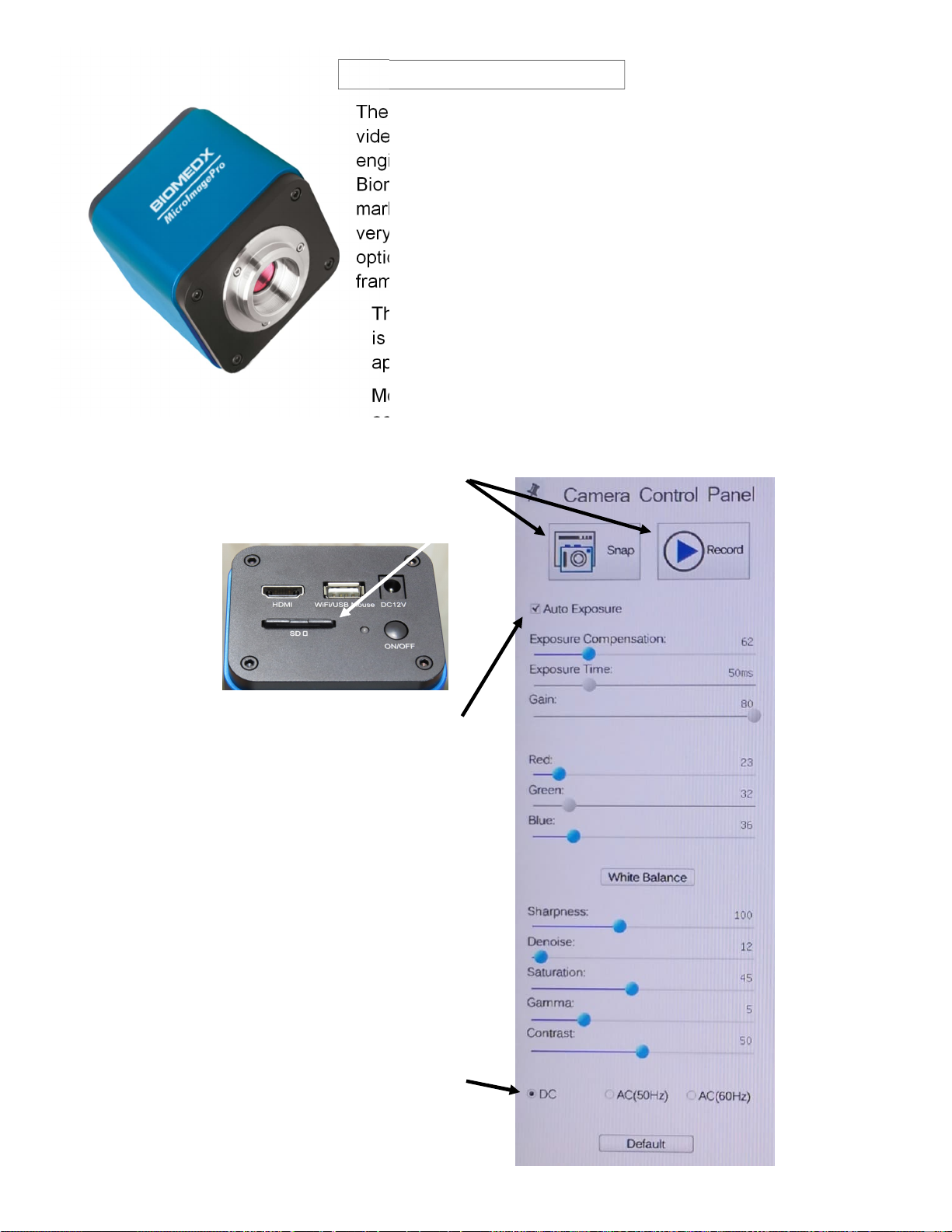
VIDEO CAMERA
The Biomedx MicroImagePro is a select high definition
video camera with internal operating software. The camera
engineers specifically adjusted the software to the
Biomedx specifications required for our live cell imaging
market. Inside there is a Sony high pixel size chipset with
very high dark signal sensitivity. Coupled to the Olympus
optics, the result is superior live video imaging at up to 60
frames per second.
The on-board software is accessed via the mouse that
is plugged into the camera’s USB port. An arrow will
appear on your TV monitor when plugged in.
Moving the arrow to the bottom edge, top edge or left
edge of the screen will bring up different menus.
Below is the monitor left edge menu.
Mouse clicks on Snap or Record will
take a picture or begin recording a
video to the SD memory card.
For everyday scope viewing in all modes, the
Auto Exposure (AE) mode should be selected
and checked.
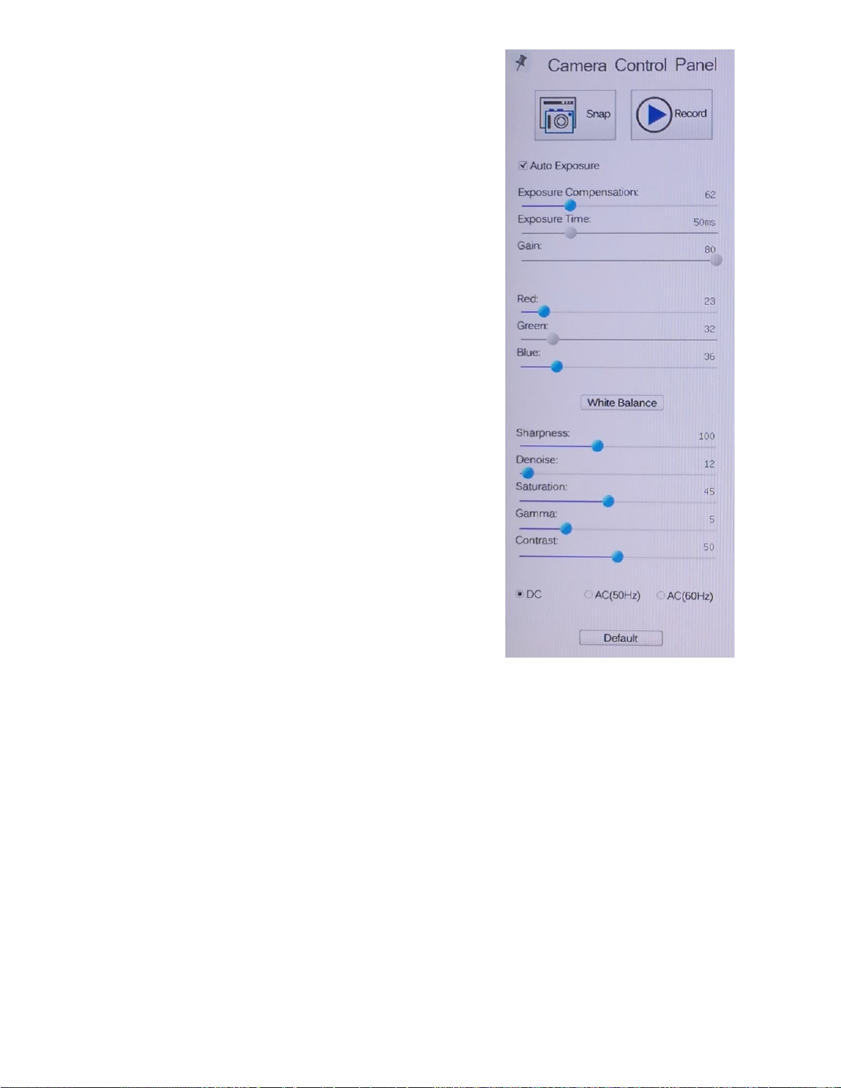
With AE set the camera will handle the
exposure details for varying light levels.
The values shown on the panel for the blue
highlighted sliders are those you can adjust
manually. Shown here are what we set them at
for testing the scope prior to shipping and they
work well for all around viewing in all modes of
the microscope but may need to be tweaked
along with your HDTV settings. They are shown
here in the event you should move the values
and forget what those starting values were.
Because the scope runs on DC powered LED
lighting the DC button is selected.
The Default button will return the camera to the
internal software’s default settings.
Page 15 v3.01.22
Your selected HDTV will have its own menu system to adjust
color, brightness, contrast, backlight, gamma, etc.
The default settings of the camera itself (values which may differ a
bit from those shown here) are a good place to leave the camera
settings and from there you can tweak your TV settings.
Because specimens can have very bright elements (like
eosinophils in blood) as well as less bright elements in the blood
plasma (like fibrin), this huge variation in light intensity is a lot for
the pixels in a camera chip to handle on equal footing. While
phase contrast handles it all very well, darkfield mode does not.
When you are in darkfield mode, you should be using the darkfield
enhancing donut to darken the background field. Decreasing the
light of the microscope may help refine the image of red blood
cells, while increasing the light may enhance elements seen in the
plasma. Increasing the Exposure Compensation on the menu may
highlight plasma elements even more and with auto exposure
turned off you can vary the overall Gain and Exposure
Compensation as well but you would need to go back to Auto
Exposure when exiting darkfield mode as there would then be too
much light and the camera would wash out.
White Balance When you press the White Balance button on the
menu, the camera will adjust the red and green values for ‘white’
depending on what the camera is looking at. Where the values
move will vary depending on the scene. Genereally White Balance
would be set while looking at a field of light in brightfield mode. If
you were in phase contrast mode, the values would be different.
The Red and Green values of Red 23 and Blue 36 are very good
for phase contrast using the LED light of the CX43. Just a single
point up or down can change the image color slightly. Whether it
needs to be tweeked may depend on your monitor. Moving the
red or blue value a single point up or down with the mouse can be
difficult. The mouse scroll wheel moves the values at 3 point
increments. To arrive at the value you want, scrolling up from 0 or
down from 200 will often land you on the value you want.
Sharpness setting from 20-150 can all look very good and
sharpen the image to your preference but where it should be
somewhat depends on your HDTV sharpness setting. With some
TVs the camera can be at 0 and the TV sharpness set higher, it
might be just the opposite for other TVs. Setting sharpness higher
can make the image appear very sharp and nice, but when
digitally zooming in, fractal patterns become evident and
decreasing sharpness will lessen that fractal effect.
The Denoise filter on the camera should not go above 9 to 12 for
live cell imaging. Set at 12 it gives a slight refinement to the
picture, above this and it starts affecting the real time movement
of blood particles too much. As the software massages the image
to refine it, the process slows down the real time movement that is
actually occurring. If that is not a concern, than a higher value
here will refine the image.
Saturation is related to how deep color renders. 45 here is about
right, your HDTV will have a level for this level as well.
Gamma adjusts the output to the
screen of the shading from white to
black. For all around scope use
using all modes of the condenser, 5
is typically a good place for it to be.
If your TV has a dark gamma to
begin with (some computer screens
have a dark gamma and can’t be
changed), bumping this down will
lighten the screen image, with some
monitors or HDTVs you will have to
increase it to 6.
Contrast at 50 is often good and
you can tweak your HDTV contrast
setting as desired or vice versa.
Some HDTV/computer monitors will
not provide great contrast and
moving this camera contrast setting
much higher will be required,
possibly more so for darkfield.

Page 16 v3.01.22
Mouse clicks
here gives you a
digital zoom and
unzoom feature.
You can get a
good image with
1 to 4 clicks of
the + box,
beyond that you
will get digital
roughness. In
some cases,
zooming in a lot
will still provide
some additional
image info. How
good may
depend on
condenser
lighting mode,
denoise filter
and sharpness
setting.
Mouse clicks on
the left box will
flip the video
image on the
horizontal, the
right box flips it
on the vertical.*
*When you
look into the
eyepieces and
move the
specimen left
to right and up
and down, the
video should
match this
movement. If
not, clicking
each box here
once will flip
the image to
match what
you see on the
monitor to
what you see
in the
eyepieces.
Moving the mouse arrow to the top edge of the video screen brings up this menu:
This menu is primarily for drawing on the screen and for use with a calibration
slide so you could calibrate your on-screen images to obtain accurate micro
measurements.
Moving the mouse arrow to the bottom edge of the video screen brings up this menu:
Freezes frame
on screen.
Puts grid lines
on screen.
WDR (Wide
Dynamic
Range) not
used.
Compares
images.
Access SD memory card to
see image and video files
you have captured or
recorded. Note that while
the camera can record the
video, you need to pull the
memory card out and put it
into a into a computer to
play them.
TOOLS: Menu/graph/
WIFI channel setup
items, video/image
capture settings, ruler
display on/off, time on/
off, misc. settings. Each
tool screen is self-
explanatory.
Note on time function: If you
want to set the date of the
camera to time stamp your
image captures, you need to
select the time function
(under miscellaneous), click
on apply, then exit and turn
off the camera. When the
camera is turned back on it
will ask you to set the date
and time. There is no internal
camera battery so when the
power is disconnected the
date and time will need to be
reset.
Internal software
version info.

Page 17 v3.01.22
Remember that all HDTVs have their own menu sengs. It is impossible to go through all
the possibilies. Below are reasonable sengs for a Vizio 24” 1080p HDTV as shown here:
This model, the Vizio D24F-F1 used on some of the scopes in our classroom works great. The
new Vizio model that replaced it is D24F-G1. Models change all the me. DO NOT GET A
COMPUTER MONITOR TO USE AS A VIEW SCREEN. For best imaging from ourvideo camera
and opmum control of the image, you need a HDTV, not a computer monitor.
KEY TO SELECTING A HDTV: When selecng a model at the store, observe the picture from
the sides and look at the screen from slightly above and below the TV. Compare it with
others that are on the same shelf. Walk down the line observing the pictures. Pick a screen
that maintains the best contrast, brightness, and definion from various angles. A few
months ago I was at Best Buy and I noced the brand Insignia with a 39” screen and 1080P
resoluon to be beer than all the others on that parcular shelf. That was surprising as it
was also only $170. More recently I saw a Samsung 32” 1080P N5300 series tobe the best
on the shelf for $250. Basically you don’t know how any TV will perform unl using it, but in
general, sck to the one with the best screen angles and it should work okay.
Example TV sengs:
Auto Brightness Control= Off
Backlight = 100
Contrast = 60
Color = 50
Tint = 0
Sharpness = 70
Color Temperature = Normal
Black Detail = Off
Backlight Control = Off
Reduce Noise Selecon
Reduce Signal Noise = Medium
Reduce Block Noise = Low
Game Low Latency = On
Gamma = 2.2
The above is what works well for our microscope work staon’s 24” Vizio model. For a
different HDTV like the Samsung 32” N5300 model, you can try similar TV sengs as shown
here but tweak as needed, andyou may needto tweak the camera a bit as well, typically the
gamma seng may move up or down by 1 point, possibly the color might need a point
movement up or down, maybe the contrast also. You will have to play with it viewing the
different modes of the scope you are using while making your fine adjustments to get it
exactly as you like it.
Page 18 v3.01.22
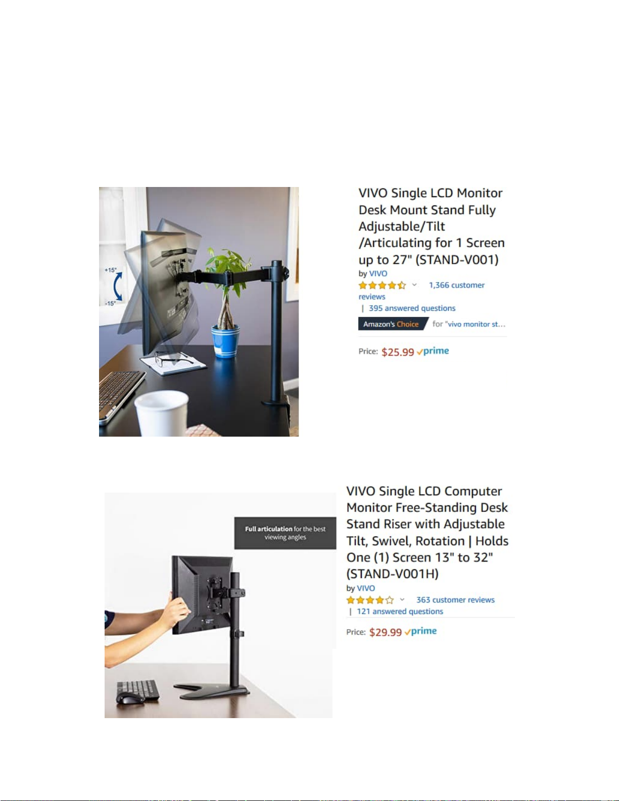
HDTVs generally have theirown built in stands. If it is not of a size you will be
mounng on a wall, then somemes it is nice to add a bit of height to the TV when it
is on a desktop.
This can be done with a monitor arm.
What we use on many of the lab staons in the Biotorium classroom is a VIVO stand.
It is shown here at Amazon for screens up to 27”, Vivo also has the same for larger
monitors:
It also comes as afree-standing unit:
Page 19 v3.01.22
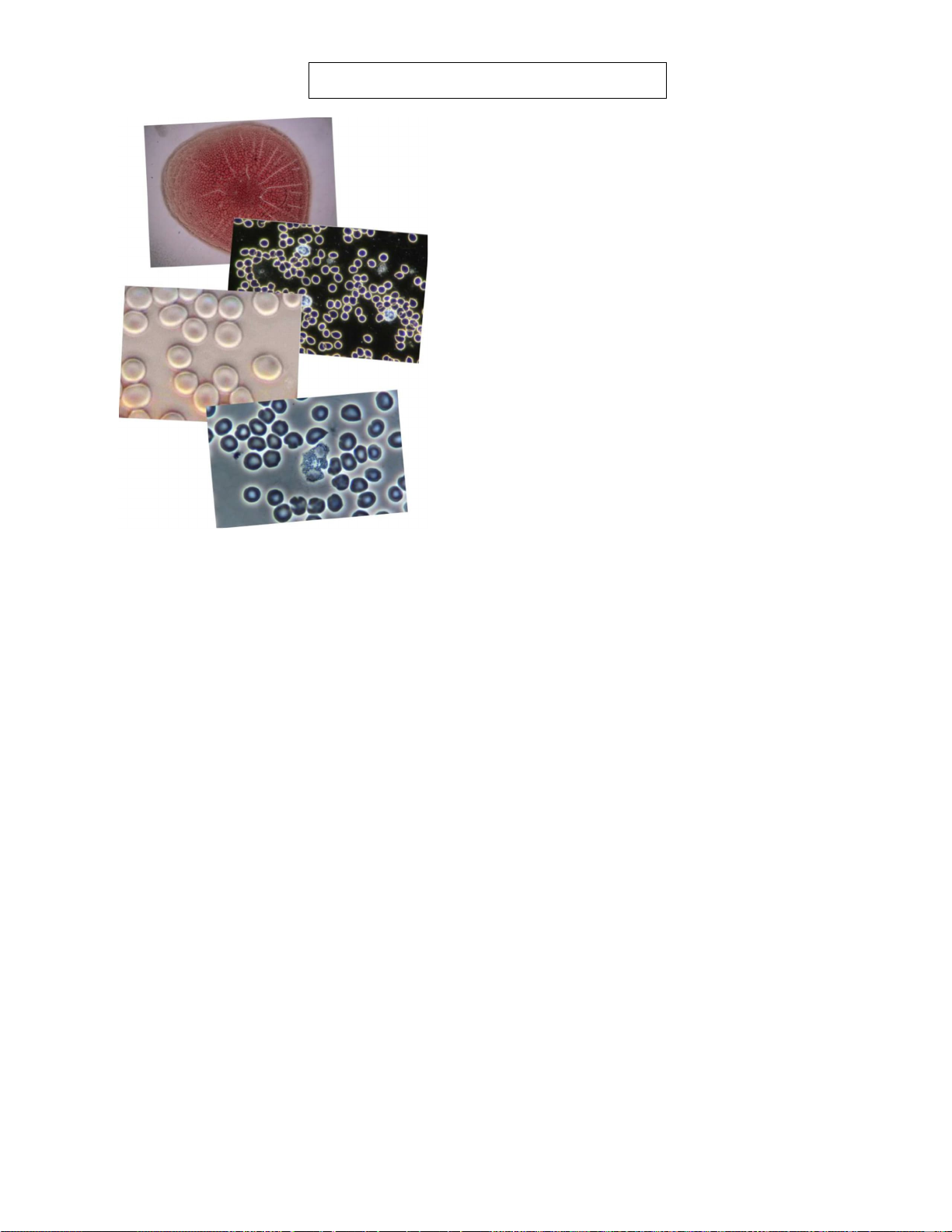
Condenser Mode Viewing Tips
The variable mode condenser provides a lot of
versatilty, particularly when using non-oil optics.
BIGHTFIELD (BF) condenser mode:
This will be used for all brighfield applications, such
as when viewing dried blood clot retraction patterns
as shown in the top image here on the left. In BF
mode when viewing on a monitor through a camera,
the field of view using a 2x optic will be on full
display (you must remove the darkfield donut or
variable aperture if this was in place.) However,
when you look through the eyepiece with the 2x, you
will see an even wider field of view and to see the
whole field, you must rotate the condenser to 2X.
The 2X condenser mode has a set iris so your depth
of field will be slightly increased. If you want a less
depth of field view on the view monitor, move the
condenser to BF mode and open the condenser iris
all the way. To zoom in on a clot retraction puddle
area, move to the 4x and 10x or even 20x.
PHASE CONTRAST (PH2) condenser mode using a 40x objective (PH1 for 20x) - bottom image above:
40x is the everyday non-oil working optic for live blood viewing on this microscope. In phase contrast
mode it has stellar image quality to provide you 99% of everything you may want to view in blood on your
video monitor providing a level of morphological contrast that darkfield does not offer. It is imperitave that
phase contrast is aligned properly. No worries here as this is done before the scope was shipped to you.
However, if you or someone else fiddled with the phase centering adjustment (explained on page 11) this
may need to be reset. Your image should look as it does above and if it does you are all set.
DARKFILED (DF) condenser mode using a 20x or 40x objective -2nd image above.
While darkfield is older technology from phase contrast, some individuals studied with others that have
used this as a primary method, often using dedicated oil condensers and oil objectives. With a non-oil
setup as we have here, some adjustment is in order to get to a better darkfield view. 2 things are required;
1) when using a 40x objective you should use the darkfield donut, and 2) you may need to turn off the Auto
Exposure mode of the camera and lower the Exposure Compensation setting. This was referenced at the
top of page 14, pay attention to the notes listed there if you are using darkfield mode a lot.
When people have adapted to the morphological richness phase contrast offers over darkfield, darkfield is
not used much, mostly to better discern nuclei in white blood cells, for doing white blood cell 100 counts,
or for observing extracelluar vesicle (EV) activity, often while zoomed in. While zooming in affects
resolution, the gray of EVs in darkfield can allow a bit more discernment of the EVs intracellular activity.
MODULATION CONTRAST (3D) - 3rd image above.
This is not a defined mode of the condenser. It is arrived at by shifting the condenser to be slightly off the
indent position of DF. When we do this we shift the light to move over our specimen more from one side of
the condenser than the other therein modulating the contrast of the image. This provides a 3D perspective
where we can see the concave or convex nature of red blood cells, target cells stand out, EVs are
highlighted, and the morphology of plaque patterns related to bong hand vessels is more easily discerned.
GINGIVAL AND URINE SAMPLE TIPS
Mosly 20x and 40x phase, see the online PDF link shown on page 2 for specimen observation procedure.

Page 20 v3.01.22
We will assume for purposes of this instruction that you have a live blood slide specimen on
your microscope stage and you have been viewing this with the 40x non-oil objective in
phase contrast (PH2) or darkfield (DF) mode.
To go to the 50x oil darkfield objective,
move the 40x objective out of the way
so you are looking at your sample as
shown in the picture. You will place a
drop or two of the microscope objective
immersion oil directly onto the top cover
slip where the 50x oil darkfield (or 100x
oil phase) objective will be rotated into
place.
After dropping on the oil, you will rotate
your oil objective into place and move it
back and forth in the oil a few times ( a
millimeter either way) to well seat the oil
around the objective lens. Your turret
condenser should be moved to DF
mode if not already there.
Oil
Using 50x oil darkfield objective.
USING OIL OBJECTIVES
Having to use oil objectives is not necessary for most specimen viewing
applications for day to day clinic and education use. However, if you are
capturing photos or video for publication purposes and require a
refinement in resolution that oil can offer, than using oil objectives may
be something you might be doing. Below are tips for using oil
Popular Microscope manuals by other brands


Nikon
Nikon Eclipse E400 POL instructions

Reflecta
Reflecta DigiMicroscope USB 200 user manual

Zeiss
Zeiss S100/OPMI pico Instructions for use

OPTIKA MICROSCOPES
OPTIKA MICROSCOPES CL-30 Operation manual

JDS Uniphase
JDS Uniphase P5000i user manual

LW Scientific
LW Scientific Revelation III LED instruction manual


