Bionet CardioCare EKG2000 User manual


C7SM-1.01
2/70
Service Manual of Cardio 2000
Revision History
Edition
Date
Page
Comment
Ver 1.0
2019-10-18
Initial Release

C7SM-1.01
3/70
Service Manual of Cardio 2000
- TABLE OF CONTENTS –
Section 1. General Information...............................................................................................5
1-1. Introduction...................................................................................................................................................................... 5
1-2. Features of the Equipment ......................................................................................................................................5
1-3. Equipment Description ..............................................................................................................................................6
1-4. System Installation .....................................................................................................................................................15
1-5. Terms of Warranty.......................................................................................................................................................16
1-6. Specification .................................................................................................................................................................16
Section 2. Troubleshooting.....................................................................................................18
2-1. Power.................................................................................................................................................................................18
2-2. Wave Printing ................................................................................................................................................................19
2-3. Diagnosis .........................................................................................................................................................................22
2-4. Filter ....................................................................................................................................................................................23
2-5. Trouble Shooting Guide ..........................................................................................................................................25
Section 3. Adjustment .............................................................................................................31
3-1. LCD Backlight................................................................................................................................................................31
3-2. Lead Fault........................................................................................................................................................................32
3-3. Filter Setting....................................................................................................................................................................33
Section 4. Block Diagram/Description ................................................................................34
4-1. Circuit Block Diagram..............................................................................................................................................34
4-2. Equipment Overview ................................................................................................................................................35
4-3. Size and Weight...........................................................................................................................................................38
Section 5. Disassembly and Assembly................................................................................39
5-1. Module Description ...................................................................................................................................................39
5-2. Internal Block Diagram & Cable........................................................................................................................46
5-3. Disassembly...................................................................................................................................................................49
5-4. Assembly.........................................................................................................................................................................59

C7SM-1.01
4/70
Service Manual of Cardio 2000
Section 6. Replaceable Parts List and Accessory.............................................................60
6-1. Replaceable Part List................................................................................................................................................60
Section 7. Connector Pin Assignment .................................................................................63
7-1. Patient Cable Port ......................................................................................................................................................63
Section 8. PCB Part Disposition..............................................................................................64
8-1. Base (Power+Analog) Board................................................................................................................................64
8-2. CDUI Board.....................................................................................................................................................................65
8-3. CPU Board.......................................................................................................................................................................66
Section 9. Software Upgrade.................................................................................................67
9-1. Requirement of Upgrading....................................................................................................................................67
9-2 Procedure of Upgrading (Cardio7 UI screen, upgrade method is same) .................................68

C7SM-1.01
5/70
Service Manual of Cardio 2000
Section 1. General Information
1-1. Introduction
CardioCare2000 is an electrocardiogram (ECG) device capable of measuring and recording 12
channels of cardiac signals of patients. The device enables operators to record cardiac signals,
review them using various viewing modes, and perform automatic detection of cardiac conditions.
In addition, the device allows operators to enter patient information for it to be printed alongside
cardiac signals, so that operators can sort and manage charts conveniently. It is also possible to
manage the digital files by transferring the stored data to a networked PC.
Furthermore, user convenience has been further enhanced by addition of a functionality that
can initiate ECG recording & saving, filter enhancing, parameter sorting and automatically
detecting cardiac signal all at once by pressing one key.
A battery (optional) can be added to the device so that the device can be operated
conveniently during bedside visits or emergency conditions.
1-2. Features of the Equipment
- Print 12-channel (ch) cardiac signals with reports in: 3ch+1 rhythm, 6ch+1 rhythm, and 12ch
rhythm patterns on A4 or Letter size printing paper.
- Record and print 12 channel rhythms continuously and simultaneously.
- Calculate heart rate, P-R-T axis and PR, QRS, QT and QTc widths from recorded signals
automatically and print them on a report for use in rhythm analysis.
- Get diagnostic reports using automatic detection functionality.
- Able to modify filter setting, signal sensitivity, printing speed, channel view settings and rhythm
settings, and print on previously recorded EKG signals to aid data analysis.
- Able to attach a battery so that the device can become portable.
- More than 200 patient‟s data can be saved and transferred to a PC through LAN.
- It offers various protocols to make it possible to link with hospitals‟ computing networks. Also File
Databases are strengthened.
C7SM-1.01
6/70
Service Manual of Cardio 2000
1-3. Equipment Description
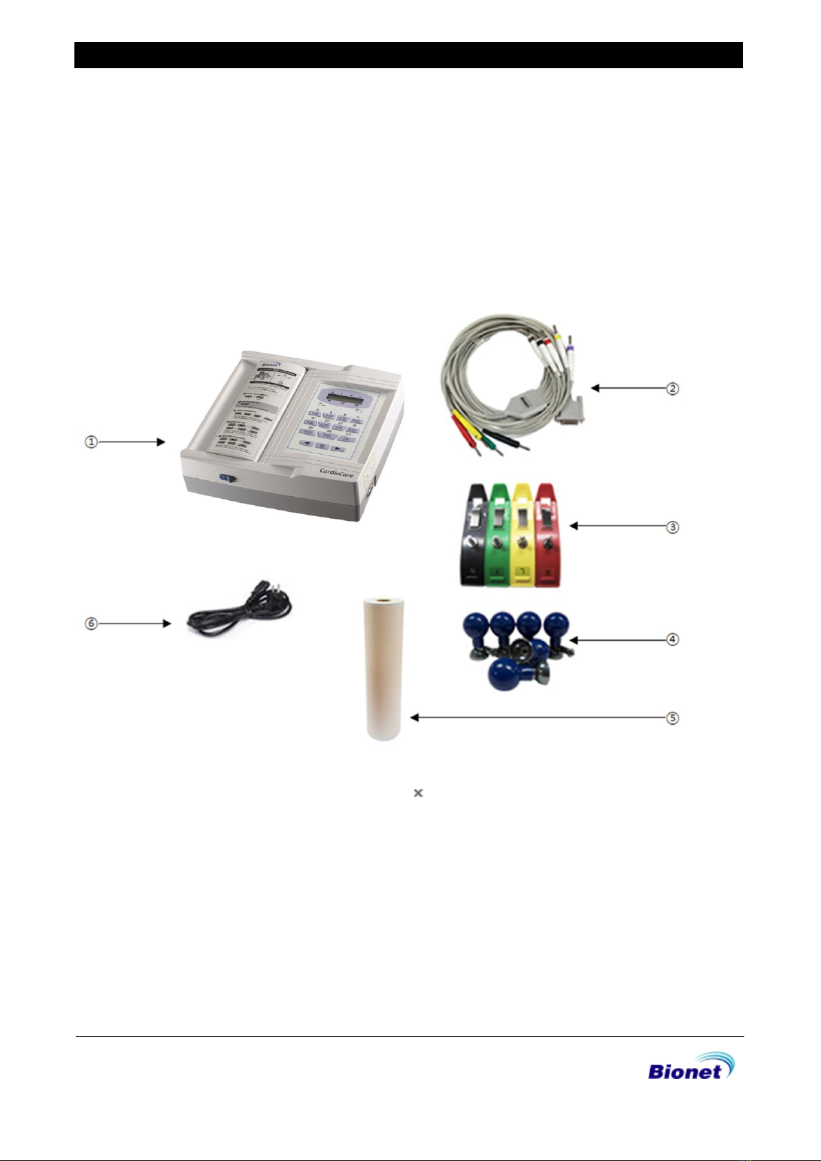
The CardioCare2000 system consists of the items below. Unpack the package and check the
items below are included. Also, be sure to check for any damage to the body and accessories.
Basic Components and Accessories
①CardioCare2000 Body (1 EA) –Dimension: 290(W) 300(D)97.5(H)mm
②Patient Cable (1 EA) –Length: 3,700mm (Max)
③Limb Electrodes (1 SET)
④Chest Electrodes (1 SET)
⑤ECG Paper (1 EA)
⑥Power Cable (1 EA) –Length: 3,000mm (Max)
C7SM-1.01
7/70
Service Manual of Cardio 2000
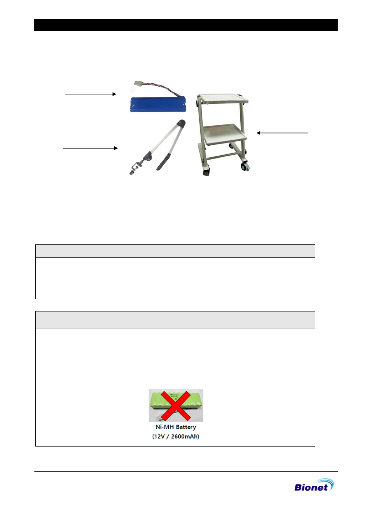
Optional Components
①Battery (1 EA) –Replaceable and Rechargeable, Lithium ion, 11.1V, 2600mA
②Hanger (1 EA)
③Cart (1 EA)
CAUTIONS
You may have distortion or signal noise when you use nonstandard or other brand
accessories. We strongly recommend you use only the authorized accessories which we
supply.
WARNING
How to replace battery: Please make sure you use the right battery we show here.
Otherwise we are not liable for any damages and/or explosion/fire caused by using the
wrong battery.
①
②
③
C7SM-1.01
8/70
Service Manual of Cardio 2000
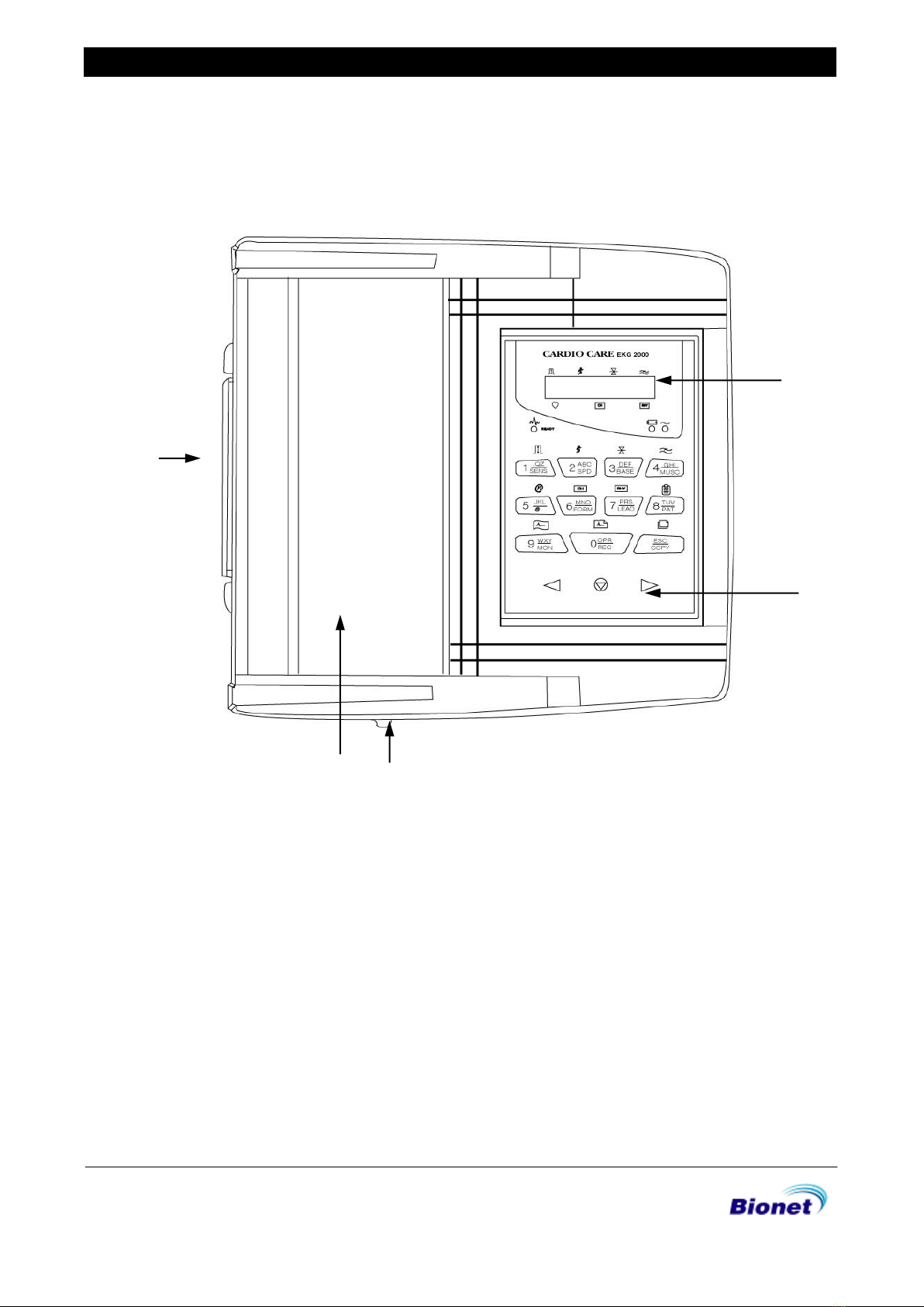
Body Configuration
▣Top View
①Handle
②Printer Cover
③Printer Cover Switch
④LCD
⑤Control Panel
①
②
③
④
⑤
③
C7SM-1.01
9/70
Service Manual of Cardio 2000
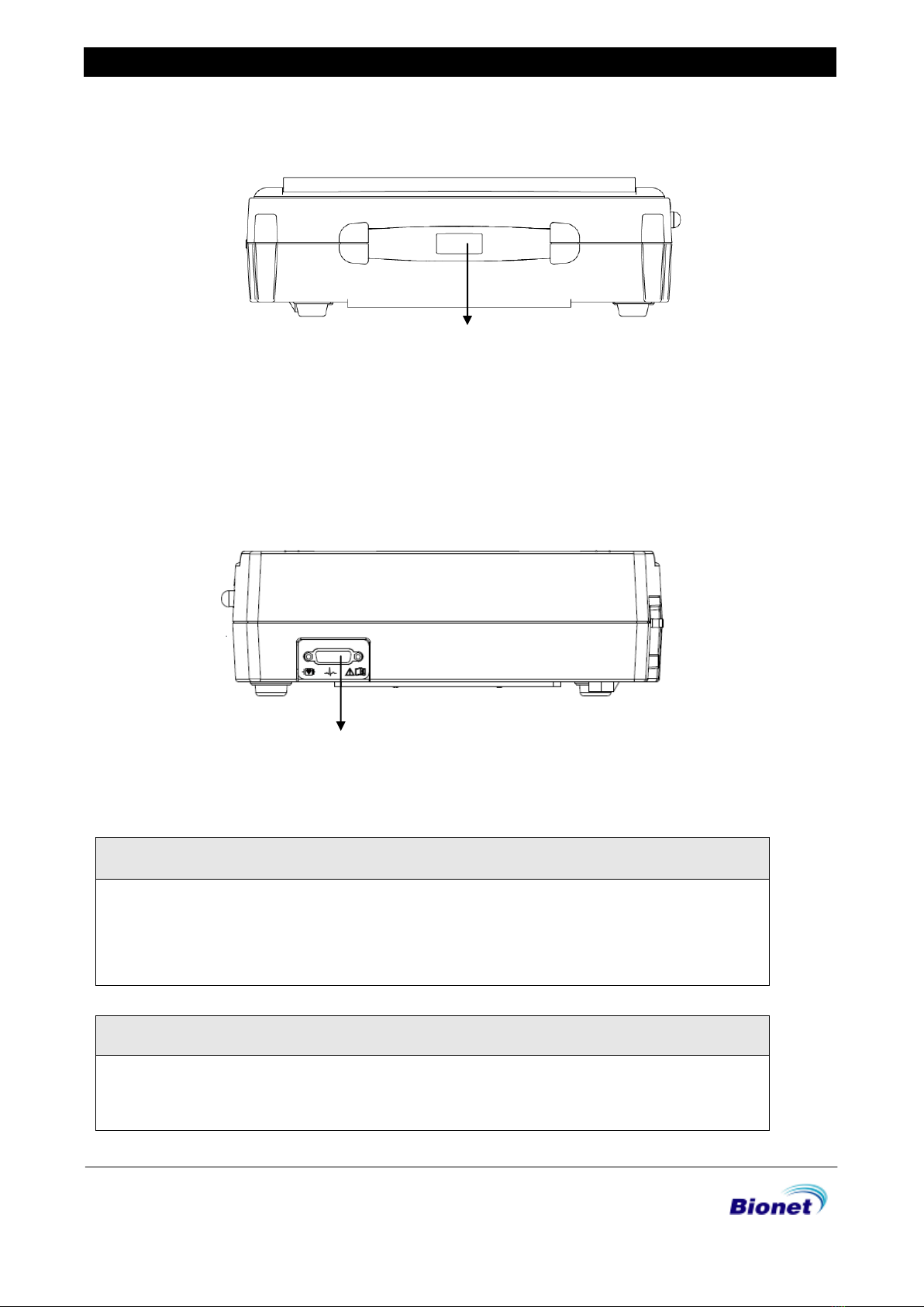
▣Front View
①Printer Cover Switch
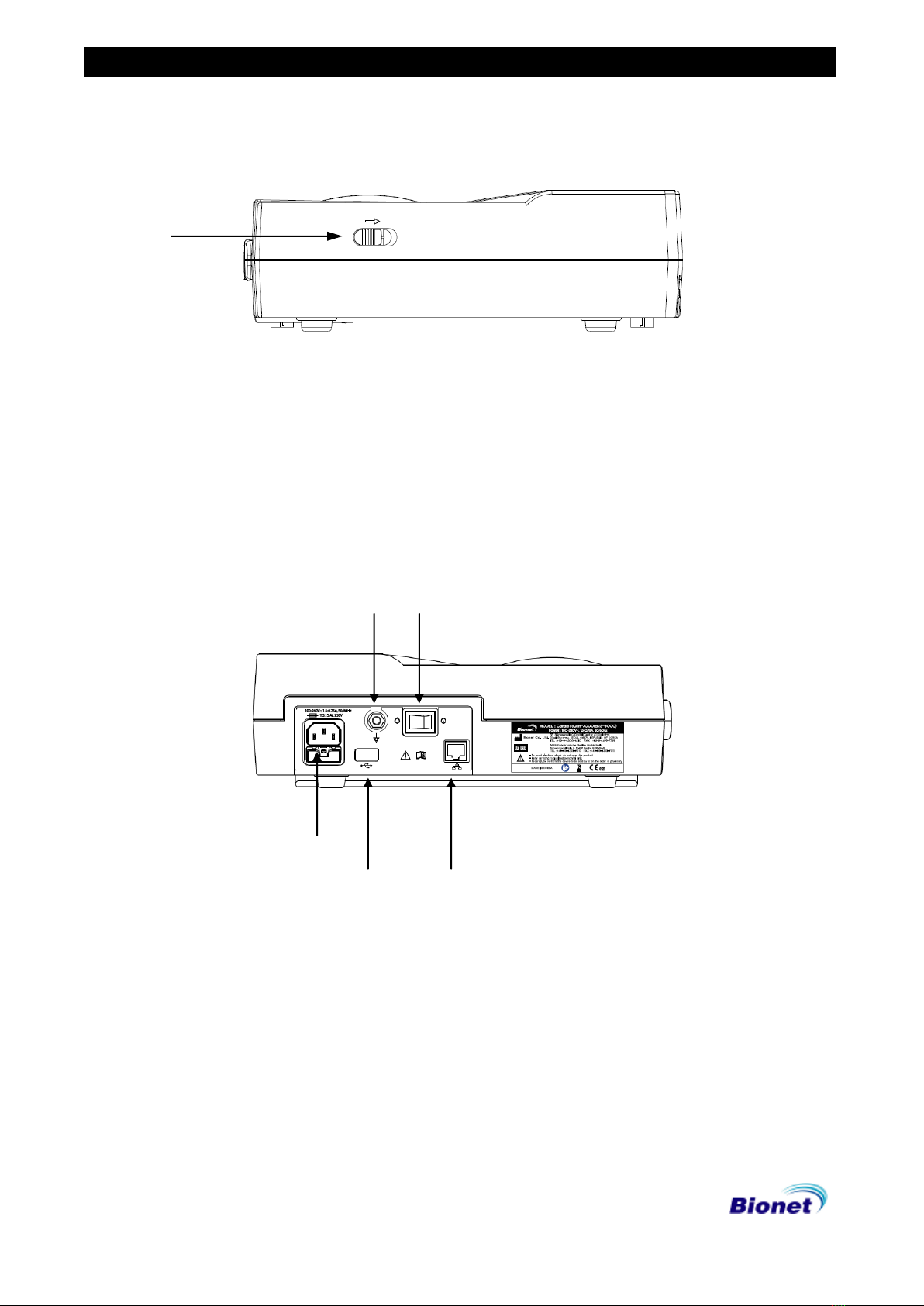
▣Rear View
①②
③
④⑤
①Protective Ground Terminal
②Power Switch
③AC Power Connection Port ( Fuse : 250V , 5A ( High breaking type ))
④USB Port(Use for equipment upgreades only)
⑤RJ45 LAN Port
①
C7SM-1.01
10/70
Service Manual of Cardio 2000
▣Left Side View
①
①Handle
▣Right Side View
①
①Patient cable connection port
WARNING
There is a risk of electric shock if the Rest stand of the equipment is damaged or can
not be fixed to the product. Do not use the product and immediately ask the
manufacturer and the seller for repair
NOTE
To avoid an expected electric shock, do not open the equipment cover or
disassemble the equipment. Refer servicing to Bionet, Inc.
C7SM-1.01
11/70
Service Manual of Cardio 2000
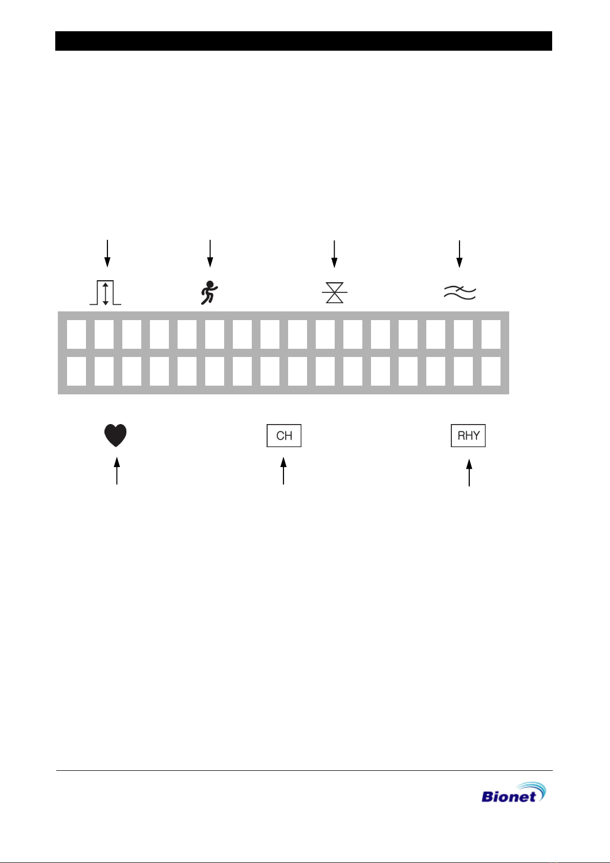
LCD Panel
LCD panel displays system setting status after indicating the version of the system and
manufacturer name for 2 seconds when power is turned on.
Displayed items on the LCD are as follows.
①②③④
⑤⑥⑦
①Display ECG signal level out of 5, 10, 20, aut (Auto Gain)
②Display printing speed out of 12.5, 25, 50
③Display base line filter setting on or off
④Display EMG filter setting on or off
⑤Display heart rate
⑥Display channel form of the output report out of 3ch+1rhy, 6ch+1rhy, 12ch rhy, 60s 1rhy.
⑦Display rhythm channel setting out of I, II, III, aVR, aVL, aVF, V1, V2, V3, V4, V5, V6..
1
0
1
2
.
5
O
F
F
O
F
F
1
0
0
6
C
H
+
1
R
H
Y
a
V
R
①
②
C7SM-1.01
12/70
Service Manual of Cardio 2000
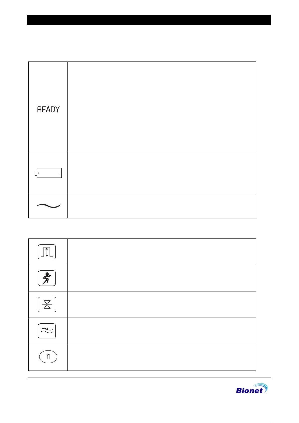
Indicator Lamp
I Indicate the lead connection status.
If LED is illuminated green, connection status is good .
If LED is off, connection status is bad.
In this case, check off which one of lead connection is in lead-off status
through monitor mode output.
Caution: Start printing when LED is illuminated green.
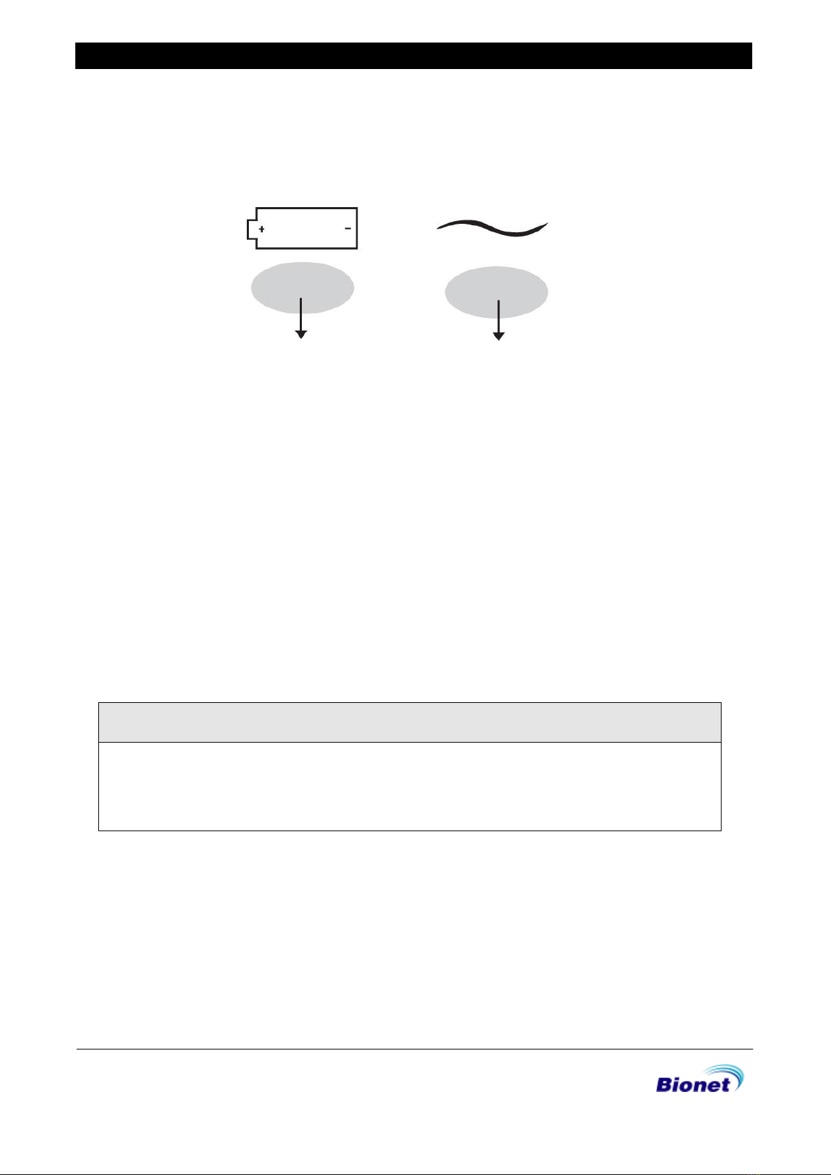
Indicate the battery capacity status: Green and Red colors are used
to display 2 different statuses.
The battery indicator is red when the device is operational without having
an A/C power supply. When an A/C power is supplied, the battery
indicator will be either red or green depending on the charge level. No
color will be shown, if there is no battery installed in the device.
Indicate AC power is operated if LED is illuminated green and not in use if
LED is off.
Control panel
Select signal level(mm/mV) out of 5, 10, 20, aut
(I-aVF:10, V1-V6:5 )
Select printing speed(mm/sec) out of 12.5, 25, 50
Select on or off whether or not to activate the filter that eliminates base line
drift
Select on or off whether or not to activate the filter that eliminates EMG.
ECG signal can be distorted by applying this filter.
This key is excepted to use when network function is added ahead.
C7SM-1.01
13/70
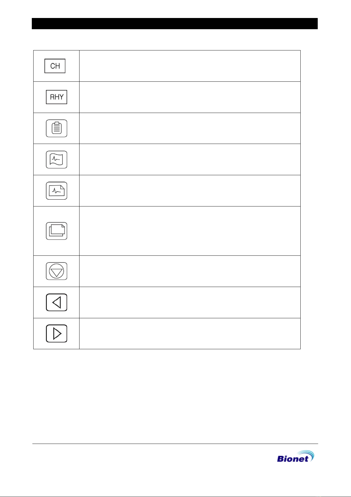
Service Manual of Cardio 2000
Select channel form of the output report out of 3ch+1rhy, 6ch+1rhy, 12ch
rhy, 60s 1rhy
Select rhythm channel
Call up the menu to enter patient ID, name, age, sex, height, weight
Display real-time ECGs from the patient continuously or monitoring the
patient ECGs for long time,
Record ECGs for 10 seconds by pressing key and prints in A4 sized report
form after calculating the measurement parameter of the recorded ECGs
Print the same report as previously printed one in record mode or prints
after changing system setting such as filter, signal level, output speed,
channel form, rhythm cannel of previously recorded ECGs data in record
mode.
Exit during printing or recording of ECGs.
Except that, call up the menu or select menu.
Move the selected focus to the left in menu mode
Move the selected focus to the right in menu mode
C7SM-1.01
14/70
Service Manual of Cardio 2000
Power
When AC power is supplied to the equipment, AC power indicator lamp at the front side is
illuminated green and battery is being charged automatically.
If no battery is installed, battery indicator lamp will be off. Once a battery is plugged in and
the device is powered on, it will change its power mode to supply power to the battery. If the
device is running on the power from the battery, battery charge indicator lamp will light up
red color. If the battery is running low on power, three continuous buzzer alarms will sound. If
this occurs, turn off the device and connect the A/C power before turning the device back
on.
-Required time for charging : more than 4 hours
-Continuous battery operating time : 1 hour
Caution
For the protection of environment, do NOT throw wasted battery away. Please inquire
at the biomedical engineering lab of the hospital and dispose according to the
appropriate procedure to the authorized place(according to national regulations).
Battery Charge
Indicator Lamp
AC Power
Indicator Lamp

C7SM-1.01
15/70
Service Manual of Cardio 2000
1-4. System Installation
Precautions for Installation
While installing CardioCare2000, please pay attention to the following items:
- Use the equipment between the ambient temperature 5 to 40℃and humidity 10 - 90%.
- Check the power cord is properly connected, and the probe carefully handled.
- Do not plug multiple cords in a power outlet.
- Install and operate unit on a flat surface.
- If you experience noise, ground the device.
- Do not use a power cord that may make a connection noise.
- Device settings will be recorded in the internal memory even when it is off.
- Prevent any shock or excessive force that may cause damage to the device.
- Place the device away from any dust or flammable materials.
Power Connection
The equipment needs electrical power to operate. Plug in one end of the power cable to wall
socket and the other to CardioCare2000.
Patient Cable Connection
- Connect the patient cable to the patient cable connection port on the right side of the body.
- Connect limb electrodes to RL (N), LL (F), RA(R), and LA (L) leads of the patient cable and chest
electrodes to V1 (C1), V2 (C2), V3 (C3), V4 (C4), V5 (C5), and V6 (C6), respectively.
Paper Installation
- Push the printer cover release switch to the right to open the printer door of the
CardioCare2000. Install EKG paper with the side to be recorded appearing on top.
Close the cover to finish the paper installation process.
WARNING
No modification of this equipment is allowed.
Do not modify this equipment without authorization of the manufacturer.
If this equipment is modified, appropriate inspection and testing must be conducted to
ensure continued safe use of equipment.
C7SM-1.01
16/70
Service Manual of Cardio 2000
1-5. Terms of Warranty
- This product was made through strict quality control and examination. The repair and
compensation standards follow the consumer damage compensation regulations of the Ministry of
Finance and Economy.
- The warranty for this product runs for 1 year. (2 years in EU) But the warranty for accessories runs for
6 months.
- This product is guaranteed against faulty workmanship for a period of 1 year. Under this warranty,
we undertake to repair free of charge at our service centers.
- When having troubles during this period, please provide us with the model name, serial number,
date of purchase and a description of the problem you are experiencing.
CAUTIONS
Federal law restricts this device to sale by or on the order of a physician
1-6. Specification
ECG Leads
Simultaneous 12 Leads Resting ECG
Recording Channel
3CH+1RHY, 6CH+1RHY, 12CH,
1CH Long Time (1min)
Gain
5, 10, 20, Auto (I~aVF: 10, V1~V6: 5) mm/mV
Printing Speed
12.5, 25, 50 mm/sec
Sampling Rate
Analysis Sampling Rate –500sample/sec
Digital Sampling Rate - 8,000sample/sec
Filters
AC (50/60Hz, -20dB or better),
Muscle (25~35Hz, -3dB or better),
Base Line Drift (off, 0.05, 0.1, 0.2Hz, -3dB or better),
Low Pass Filter(off, 40Hz, 100Hz, 150Hz)
C7SM-1.01
17/70
Service Manual of Cardio 2000
Display
2 x 16 Char LCD Display
Sensitivity, Speed, Filter Status, HR, Printing Form, Rhythm Lead
User Interface
Short Key
Printer Resolution
Thermal Print Head, Roll Paper
Report Paper
- Width: A4/Letter –215mm (8.5”)
- Length: A4 –297mm (11.7”)
Letter –279mm (11”)
Resolution: 8dot/mm (0.125mm pitch)
Patient data
ID, Name, Age, Gender, Height, Weight
Basic Measurement
Heart Rate: 30~300bpm (±3bpm)
PR, QRS, QT/QTc, P-R-T axis
Electrical
Internal Noise: 20uV(p-p)max
Input Impedance: More than 50MΩ
Input Voltage range: ±5mV
CMRR: Greater than 105dB
DC offset Voltage: ≥ ±400mV
Patient Leakage Current: < 10uA
Frequency Response: 0.05~150 with in –3dB
Isolated, Defibrillation and ESU Protected
Line Power
Input: 100- 240Vac, 1.5-0.75A, 50-60Hz, Output: 15Vdc, 4.2A
Battery type
Replaceable and Rechargeable, Lithium ion, 10.8V, 3350mA
Battery Capacity
360 minutes of continuous operation without recording or
200 ECGs in 12 channel format at 25mm/s and 10mm/mV
with a battery charged during approximately 3 hours from total
discharge (with display off)
Communication
LAN
Safety Conformity
Class I, Type CF Defibrillation-proof applied Part.
Environmental
Operating Temperature: 5~40℃
Operating Humidity: 10~90%RH
Atmospheric Pressure: 70~106KPa
Dimensions
290(W) 300(D)97.5(H)mm, Approx 3.0kg (Main Body)
Standard Accessory
Patient Cable (1 EA), Limbs Electrodes (1 SET),
Chest Electrodes (1 SET), ECG Paper (1 EA),
Power Cord (1 EA)
Options
Rechargeable Battery (1 EA),
Cart(1 EA), Hanger (1 EA)
C7SM-1.01
18/70
Service Manual of Cardio 2000
Section 2. Troubleshooting
2-1. Power
Problem
Solution
Case1.
The EKG2000
open will turn on
and off
frequently.
Case2.
Power will not
turn on.
< General Checking >
1. Check the power cable is connected with AC Power connection at the
back of the system.
2. Check the power source of the multi-tab with connection to the power
cable. (If power is connected, AC power indicator is lighted.)
3. Check the power switch.
4. Check any of two fuses on the Power Module (SMPS) and on fuse on the
Base board is cut.
If it is, replace Power board.
Case1:
Check if the soldering of J1 on the Base board (SMPS + Base board
Connector) is poor. Re-solder the cable.
● When the EKG2000 is turned on, the pin no. 8‟s voltage has to be always
14.6V.
1) Is the pin no. 1/2‟s voltage is 14.6Yes replace the main board.
2) Is the pin no 1/2‟s voltage is 14.6No replace the power board.
● When the REC key is pressed,(during printer is working)
1) Pin no. 12‟s voltage has to be changed from 0V to 24V
If not, faulty power board, replace the power board.
2) Pin no. 15‟s voltage has to be changed from 3V to 0V.
If not, faulty CPU, replace the main board.
C7SM-1.01
19/70
Service Manual of Cardio 2000
2-2. Wave Printing
Problem
Solution
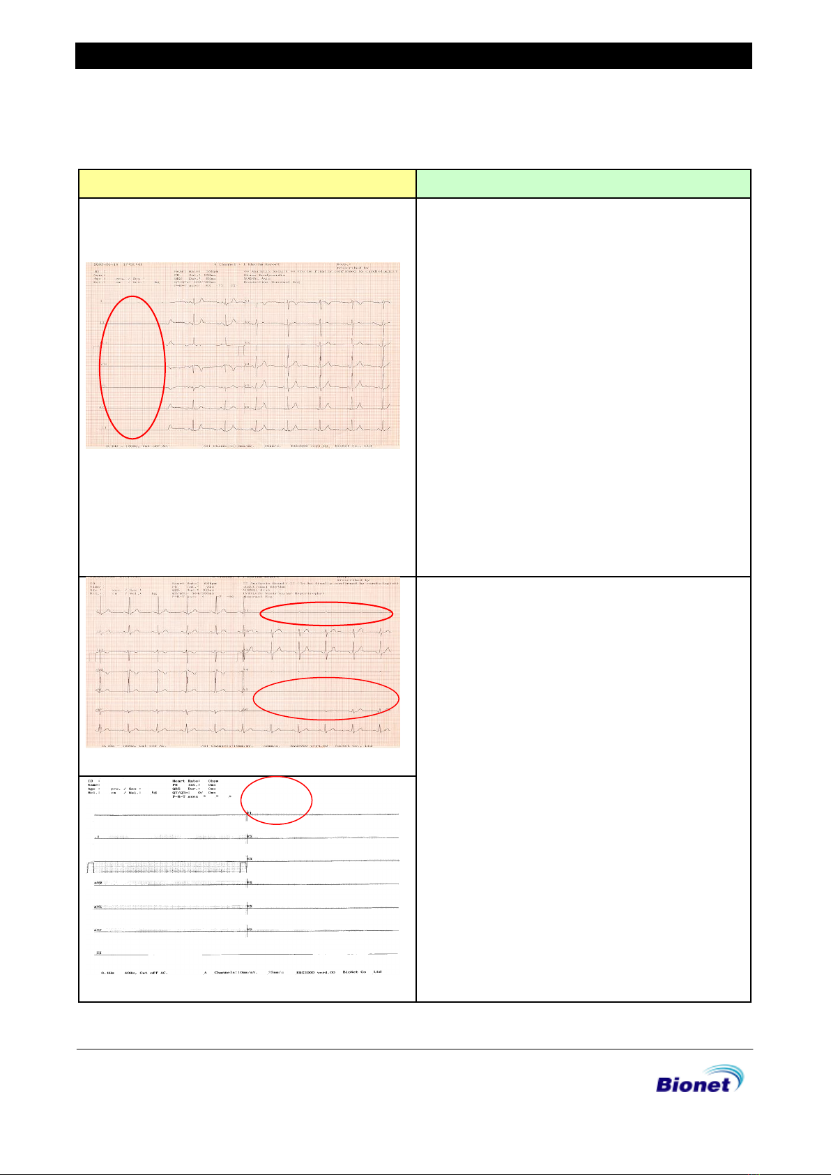
1-1. The wave pattern changes from the flat line
on the left to the wave forms on the right.
1. If the normal wave patterns show up to the
right of chart as shown in problem1, 2,
diagnosis output print too early.
2. It takes some time to show the normal wave
patterns.
3. The normal wave patterns will show if output
is requested after the system is stabilized
by showing the HR variance of ±5 on the LCD
display.
4. Check connection of the limbs electrode
and the chest electrode to the body parts.
5. If used on the dry skin or in the winter
season, connectivity may be degraded. In
that case, used water or ECG gel. The
electrode must be washed after using ECG
gel. Otherwise, the electrode will be rusted
and corroded.
1-2. Some wave patterns are not shown in V1~6.
* Connection location of the limbs electrode
and the chest electrode
2. The diagnosis is not shown in print.
1. Press the menu key, showing the overlapped
circle and triangle, at the bottom of the
Keypad.
2. Press the right arrow button twice to select
PRN and then press the menu key.
3. Press the left arrow button once to select
DIAG and then press the menu key.
4. Press ESC key from the menu to enter the
basic display and then press '0' to printout.
C7SM-1.01
20/70
Service Manual of Cardio 2000
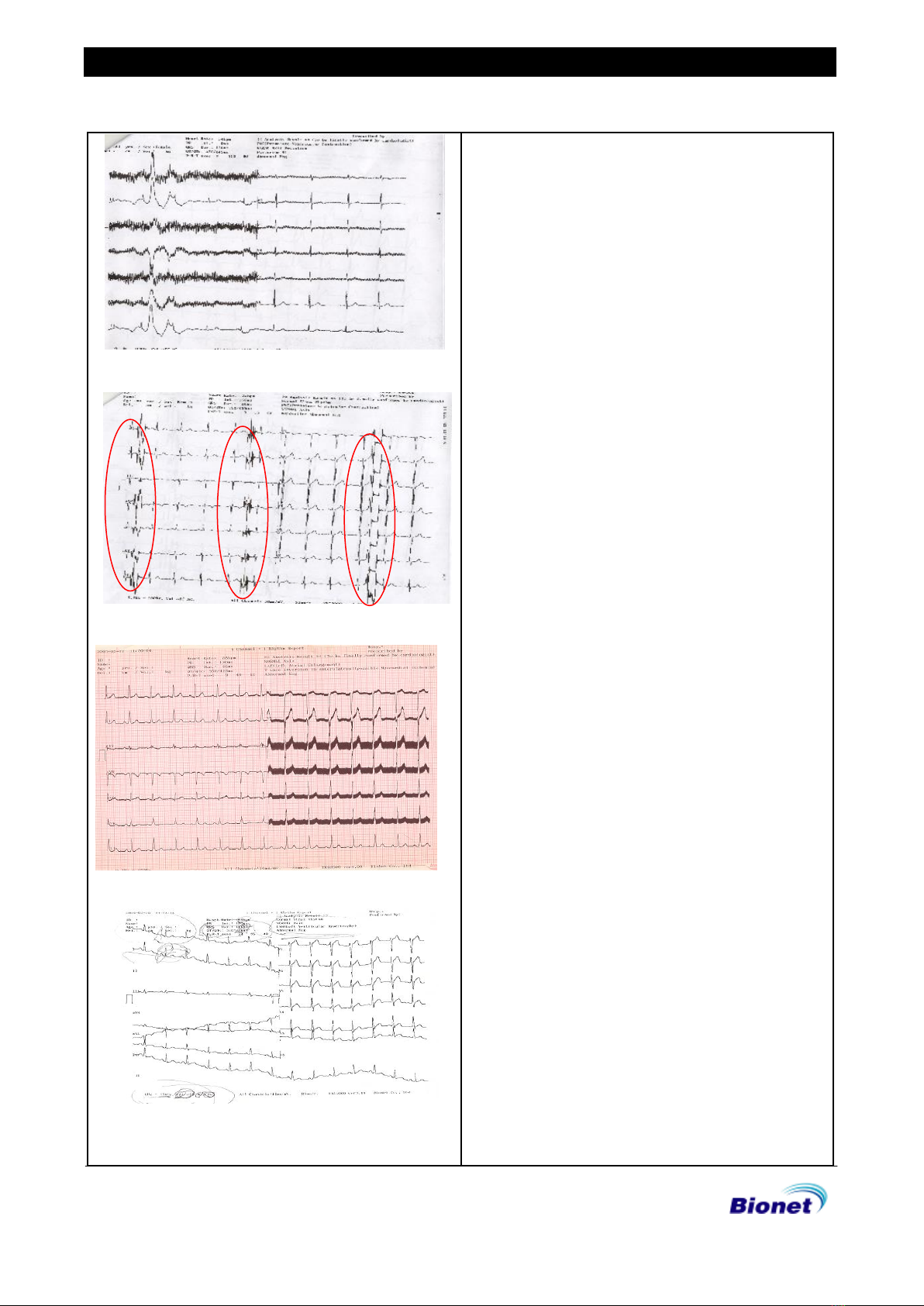
3-1. There are too many noises in the wave
pattern.
3-2. The noises periodically occur throughout
the wave patterns.
3-3. The thick noise is made on the wave
patterns.
3-4. The wave output looks like the noise and
are not properly shaped.
1. This problem occurs when the filter value is
not corrected.
2. Press the menu key, showing the overlapped
circle and triangle, at the bottom of the
Keypad.
3. Press the right arrow key once to select FLT
and then press the menu key.
4. Check if the filter value shows BASE: ON,
MUSC: OFF, AC: 60 Hz, LDF: 150Hz and, if not,
correct it.
5. Since the noise occurs as in problems 2 and
3 if the AC filter is turned off or set at
different frequency from the power source,
the system must be set at 50Hz or 60Hz to
correspond to the input power. (It is different
each country) The AC filter status is shown at
the left bottom of the printout as
'CUT OFF (ON) AC'.
6. Problems 3.4 occurs when the BASE is set at
OFF. Change it to ON.
Table of contents
Other Bionet Medical Equipment manuals

Bionet
Bionet BM3Vet Pro User manual

Bionet
Bionet Cardio 7 User manual

Bionet
Bionet CardioCare 2000 User manual

Bionet
Bionet Cardio7e User manual

Bionet
Bionet BM3 User manual

Bionet
Bionet Cardio P1 User manual

Bionet
Bionet CardioXP User manual

Bionet
Bionet Cardio7 User manual

Bionet
Bionet BM1 User manual

Bionet
Bionet Cardio7 User manual

Bionet
Bionet BM7VET User manual

Bionet
Bionet FC1400 User manual

Bionet
Bionet BM3 User manual

Bionet
Bionet BM1 User manual

Bionet
Bionet Oxy9Wave Vet User manual

Bionet
Bionet Cardio7 User manual

Bionet
Bionet BM Elite Series User manual

Bionet
Bionet BM1VET User manual

Bionet
Bionet BM5 User manual

Bionet
Bionet BM5 User manual


