Bionics IFM-500 User manual

Head Office/Factory
687-5, Sangoan-ri, Hongcheon-eub, Hongcheon-gun,
Gangwon-do, Korea (zip.250-804)
Tel : +82-33-434-9041 Fax : +82-33-434-9043
Seoul Office/R&D
3F, Kwangsung Venture Plaza, 445, Daehung-dong, Mapo-gu,
Seoul, Korea, 121-080, Republic of korea
Tel : +82-2-714-2962 Fax : +82-2-714-2963
Customer Service Dept.
Tel : +82-2-714-2962 Fax : +82-2-714-2963
IFM500(영문) 1904.2.3 9:48 PM 페이지1 001 pdf-in
Operation Manual
IFM-500
FETAL MONITOR Ver 1.4
IFM500(영문) 1904.2.3 9:48 PM 페이지2 001 pdf-in

IFM500(영문) 1904.2.3 9:48 PM 페이지3 001 pdf-in

Table of Contents
1. INTRODUCTION
3
2. SAFETY PRECAUTIONS
4
2.1 Proper Environment for the use of IFM-500
4
2.2 Electrical Safety precaution
6
2.3 Maintenance and protection
8
2.4 Fuse Replacement
9
3. SPECIFICATIONS
10
3.1 Standard Specification
10
4. PRODUCT DESCRIPTION
12
4.1 Composition of IFM-500
12
4.2 Name of Each part
13
5. INSTALLATION
17
5.1 Transducer and Evevnt maker Connection
17
5.2 Recordfing paper Installation
18
5.3 Power Connection
18
6. SET-UP MODE
19
6.1 Initial Set-UP
19
6.2 Set-up Function
20
7. OPERATION
26
7.1 Control panel
26
7.2 FHR(Fetal Heart Rate)
28
7.3 UC(Uterine Contraction)
29
7.4 Alarming
29
7.5 Recording
29
7.6 Evevnt Marking
30
7.7 Self-test(Calibration)operation
30
8. HOW TO USE TRANSDUCERS
31
8.1 Doppler measurement method
31
8.2 UC measurement method
33
9. ERROR MESSAGE AND COUNTERMESURE
34
10. RECORDING PAPER
35
A. AFTER SERVICE
37
B. WARRANTY
39
IFM500(영문) 1904.2.3 9:48 PM 페이지4 001 pdf-in

IFM500(영문) 1904.2.3 9:48 PM 페이지5 001 pdf-in
Notes To Users
1
IFM-500
Preface
■
Thank you for purchasing the IFM-500 Fetal Monitor. To ensure safe operation and long term
performance stability, it is essential that you fully understand the functions, operating and
maintenance instructions by reading this manual before operating equipment.
■
Particular attention must be paid to all warnings, cautions, and notes incorporated herein.
●
Incorrect operation, or failure of the user to maintain the equipment relieves the
manufacturer or his agent of the system’s noncompliance with specifications or of
responsibility for any damage or injury.
●
The following conventions are used throughout the manual to denote information of special
emphasis.
“Warning” is used to indicate the presence of a hazard which can cause severe personal
injury, death, or substantial property damage if the warning is ignored.
“Caution” is used to indicate the presence of a hazard which will or can cause minor personal
injury property damage if the caution is ignored.
“Note” is used to notify the user of installation, operation, or maintenance information which
is important but not hazard related.
Notes To Users
IFM500(영문) 1904.2.3 9:48 PM 페이지1 001 pdf-in
FETAL MONITOR
2
Safety Symbols
Safety Symbols
■
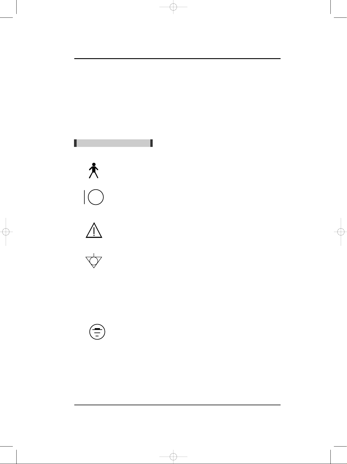
The International Electrotechnical Commission (IEC) has established a set of symbols for
medical electronic equipment which classify a connection or warn of any potential hazards.
The classifications and symbols are shown below.
Save these instructions.
■
The following symbols are used inside the system :
Isolated patient connection. (IEC 601-1-Type BF)
I and O on power switch represent ON and OFF, respectively.
This symbol identifies a safety note. Ensure you understand the
function of this control before using it. Control function is described
in the appropriate operation manual.
Conductor provides a connection between equipment and the
potential equalization busbar of the electrical installation.
Identifies the point where the system safety ground is fastened to the
chassis.
Protective earth connected to conductive parts of Class I equipment
for safety purposes.
IFM500(영문) 1904.2.3 9:48 PM 페이지2 001 pdf-in

Introduction
3
IFM-500
Thank you for your purchase of BIONICS FETAL MONITOR (IFM-500).
IFM-500 has been designed for the users’best convenience. Exact and stable FHR(Fetal
HeartRate), UC(Uterine Contraction) and FM(Fetal movement) extracted automatically by using
Doppler Shift Frequency are displayed and recorded for monitoring up to fetal status.
Customers are kindly requested to read through this operational manual describing general
instruction before installing and using.
In chapter 2, safety precautions are described.
In chapter 3, standard, optional specification and serial interface for computer connection are
described.
In chapter 4, composition and name of each parts are described.
In chapter 5, pre-steps for installing and power supply before using are described.
In chapter 6, changing and memorizing of each parameters of set-up mode are described.
In chapter 7, operation of IFM-500 are described.
In chapter 8, how to use transducers effectively for FHR and UC monitoring are described.
In chapter 9, first aid treatment for emergency trouble are described.
In chapter 10, all data recorded in recording paper are described.
In appendix A, after service steps are described.
In appendix B, warranties are described.
INTRODUCTIONCHAPTER 1
IFM500(영문) 1904.2.3 9:48 PM 페이지3 001 pdf-in
FETAL MONITOR
4
Safety Precautions
1. INTRODUCTION
2.1. Proper Environment for the Use of IFM-500
●The IFM-500 is designed and manufactured with due consideration given to the safety of
the operator and subject and also to the reliability of the equipment. The following
precautions must be observed for additional safety :
①
The equipment must be operated only by, or under supervision of, aqualified person.
②
The IFM-500 is specified as Class I type BF equipment under the standard of IEC
60601-1 (Safety of Medical Equipment).
Therefore, Patients must not touch or handle the equipment at any time.
③
Do not modify the equipment. If any modification is desired, ask MEDISON or its
authorized dealer for the service.
④
The equipment has been factory-adjusted for optimum performance.
Do not attempt to adjust any preset controls or switchs except those specified in this
manual for operation.
⑤
If you have experienced any trouble with the equipment, switch it off immediately, and
contact BIONICS or its authorized dealer for assistance.
⑥
If you plan to connect any devices of other manufacturers electrically or mechanically to
this equipment, contact BIONICS or its authorized dealer for instructions before doing
so.
⑦
Avoid the following environments for operation or storage ;
●where the equipment is exposed to toxic gas.
●where the humidity is extremely high.
●where the equipment is exposed to wator vapor.
●where the equipment is exposed to spray or splashing water.
CHAPTER 1 SAFETY PRECAUTIONS
No protection against the ingress of liquids.
IFM500(영문) 1904.2.3 9:48 PM 페이지4 001 pdf-in
Safety Precautions
5
IFM-500
●where the equipment is exposed to dust.
●where the equipment is exposed to high density oil vapor.
●where the equipment is exposed to salty atmosphere.
●where the equipment is exposed to explosive gas or dust.
●where the equipment is exposed to excessive shocks or vibrations.
●where the angle of inclination of the mounting surface excessive 10 degrees.
●where the AC power line voltage heavily frustrates.
●where the AC power line voltage changes heavily with this equipment in operation.
●where the equipment is exposed to direct sunlight.
⑧Avoid the following environments for operation, storage and transport ;
●where the ambient temperature falls below -10℃or exceeds 60℃.(Normal operating
temperature range = 10 to 40 ℃)
●where the atmospheric pressure falls below 70 KPa (700 mbar) or exceeds 106 KPa (1060
mbar).
●where the humidity falls below 30 or exceeds 85%.
For environmental protection, never dispose lithium battery IC to hazardous places : like fire
hazardous places.
IFM500(영문) 1904.2.3 9:48 PM 페이지5 001 pdf-in
FETAL MONITOR
6
Safety Precautions
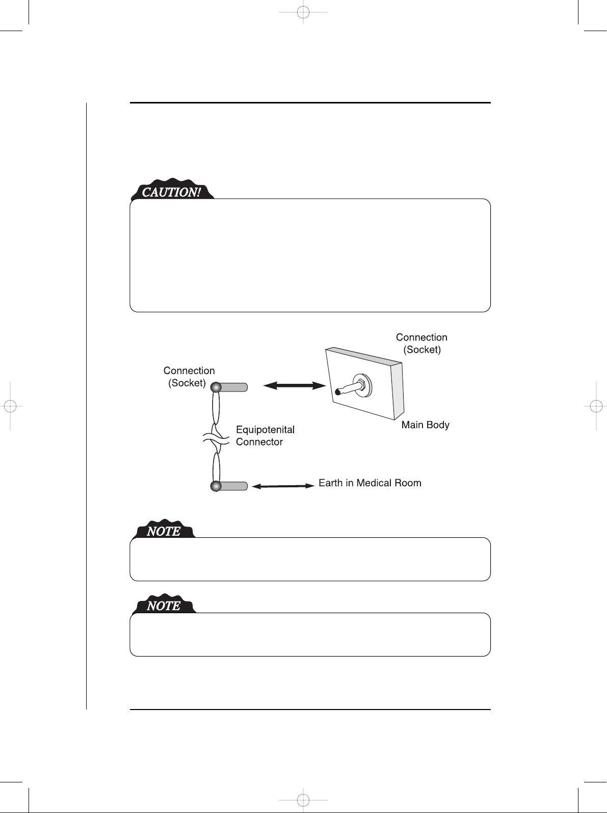
2.2. Electrical Safety Precaution
EQUIPOTENTIAL BONDING ;
In hospital, doctors and patients are subjected to dangerous, uncontrollable compensating
currents. These currents are due to the potential differences between connected equipment and
touchable conducting parts as found in medical rooms. The safest solution to the problem is
accomplished is consistent equipotential bonding.
Medical equipment is connected with connecting leads made up with angle sockets to the
equipotential bonding network in medical rooms.
Try to place the system far from power generators, X-ray machines, broadcasting stations, and
transmission lines to avoids electrical noise during diagnosis.
The equipment and the additional devices are to dispose safe after the life cycle of the
equipment.
IFM500(영문) 1904.2.3 9:48 PM 페이지6 001 pdf-in

Safety Precautions
7
IFM-500
IFM-500 is classified as ;
- Class I type-BF against electric shock
- Ordinary equipment without protection against ingress of water
- Equipment not suitable for use in presence of a flammable anesthetic mixture
- Continuous operation by standard of IEC 60601-1 (Safety of Electric Medical Equipment).
Moreover, IFM-500 is complied with Class A for Noise-Emission, Level B for Noise-
immunity, by standard of IEC 60601-1-2 (Electromagnetic Compatibility Requirements).
IFM500(영문) 1904.2.3 9:48 PM 페이지7 001 pdf-in
FETAL MONITOR
8
Safety Precautions
2.3. Maintenance and Protection
●To keep the system and probe clean, rub them smoothly with a soft cloth soaked it in the warm
water or dampened with alcohol at least once a month. Do not use lacquer thinner ethylene
oxide or any other organic solutions, as this can destroy the membrane of the probe. Make sure
that disinfecting solution or water does not go into the system and other accessories.
●To clean probes, the standard practice for cleaning is to gently but thoroughly wipe probes
with either a warm, water-moistened cloth or a standard clinical-grade alcohol prep pad at
least once in a week. Do not use lacquer thinner or other orga-nic solvents as this can have
deleterious effects on the active membrane surface of probes. Do not immerse probes in any
type of liquid or cleaning solution. Also, do not allow liquid of any type to leak into the system
or probes.
When a patient use mark switch, Be sure to wear the medical gloves or similar poretection
things to avoide contact.
■■Cleaning
■■Biocompatibilty Protection.
The belt contains natural Rubber Latex which may cause allergic reactions.
IFM500(영문) 1904.2.3 9:48 PM 페이지8 001 pdf-in
Safety Precautions
9
IFM-500
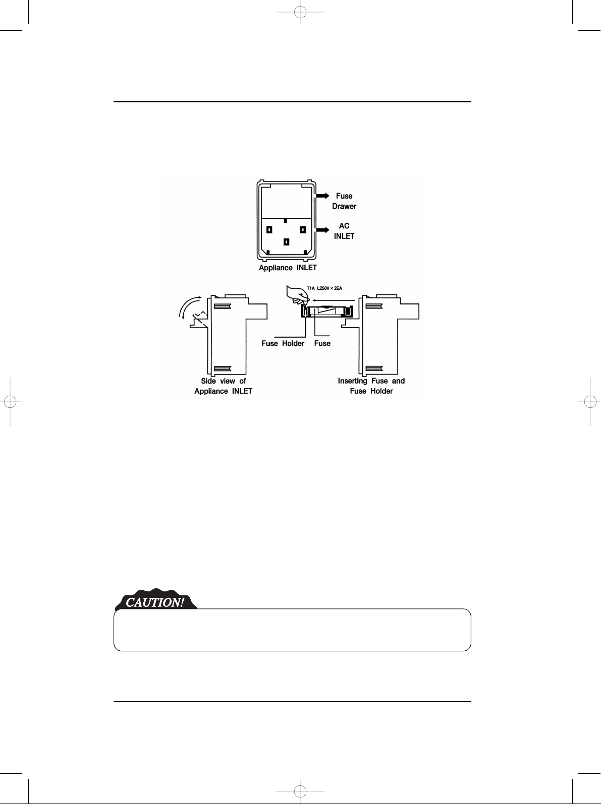
2.4. Maintenance and Protection
1. Open fuse drawer on the upper side of the appliance inlet, there will be the two small fuse
holder.
2. Push the fuse holder toward the arrow direction, and pull the fuse holder toward the upper
side of the appliance inlet.
3. Remove the old fuse by pulling up.
4. Install the new fuse by pushing to the fuse holder.
5. Insert the fuse holder to the appliance inlet. At this time, the arrow direction on the upper side
of the fuse holder should be in accordance with that on the fuse draw.
6. Also, the same method is used to exchange the other fuse holder.
7. Close the fuse drawer.
For continuous protection against a risk of fire hazard, replace only with same type and same
rating of fuse.
IFM500(영문) 1904.2.3 9:48 PM 페이지9 001 pdf-in

FETAL MONITOR
10
Safety Precautions
3.1. Standard Specification
1) Operating Frequancy : 2 MHz
2) Intenity : 10rm mW/cm2or less
3) FHR Measurement
- Dual FHR display and recording
- Measurement range : 50 ∼240 bmp(beat per minute)
- Fetal heart beat sound
- Fetal heart beat rhythm lamp
- Signal quality indication (Green: good, Red: noise present)
- FHR alarming function
- Auto-recognition of transducer used (selection lamp)
4) FM Measurement
- Auto measurement by using doppler shift frequency
5) UC Measurement
- External measurement (Guard ring method))
- Calibration function
- UC Value display on LED BAR
- UC Value display and recording
6) Recording printer
- Thermal head
- Resolution : 8 dots/mm
- Record speed : selectable 1, 2 and 3 cm/min
- Duration: 16 hours (3cm/min)
- Record contrast : 4 steps
- Auto-record period : 10, 20, 30, 40, 50, 60 minutes
SAFETY PRECAUTIONSCHAPTER 3
IFM500(영문) 1904.2.3 9:48 PM 페이지10 001 pdf-in

Safety Precautions
11
IFM-500
7) Set-up Function
- Date and time
- Record speed
- Record contrast
- Auto-record period
- Upper and lower value for alarming
8) Power required
- Input : 100 - 240V ~, 50/60 Hz
- Power consumption : Abt. 40W
9) Others
- Event marker
- Self-test(Calibration) function
- Serial Interface function for computer loaddown(RS-232C)
- Size : Abt. 230(W) ×280(H) ×210(D) mm
- Weight : Abt. 4 Kg
IFM500(영문) 1904.2.3 9:48 PM 페이지11 001 pdf-in

FETAL MONITOR
12
Product Description
4.1. Composition of IFM-500
Open the packing box and check if main unit and all related accessories are staying in.Also check
the breakage and damages which can be happen during transportation.If any related accessories
are missing, please inquire the situation to seller.
1) Standard Accessories
①IFM-500 Main Body
②Ultrasound transducer(1EA)
③Tocotransducer(1EA)
④Event marker(1EA)
⑤Printer paper(2EA)
⑥Power cord and adaptor(1 EA)
⑦Ultrasound gel(1EA)
⑧Belt(2EA)
⑨Grounding wire(1EA)
⑩Transducer hanger(1EA)
⑪Operational manual
2) Optional Accessories
①RS-232C connection cable
②Cart
CHAPTER 4 PRODUCT DESCRIPTION
IFM500(영문) 1904.2.3 9:48 PM 페이지12 001 pdf-in
Product Description
13
IFM-500
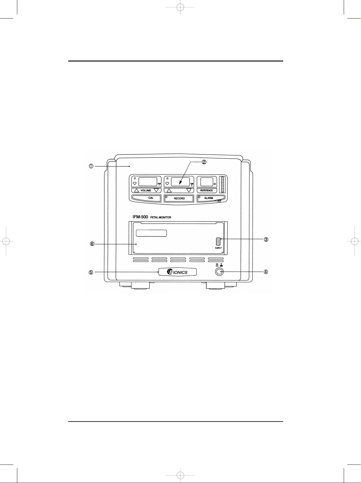
4.2. Name of Each part
■■Front panel
(1) Front cover
(2) Operating panel
(3) Open knob
(4) Power switch
(5) Logo label
(6) Door panel
Function
IFM500(영문) 1904.2.3 9:48 PM 페이지13 001 pdf-in
FETAL MONITOR
14
Product Description
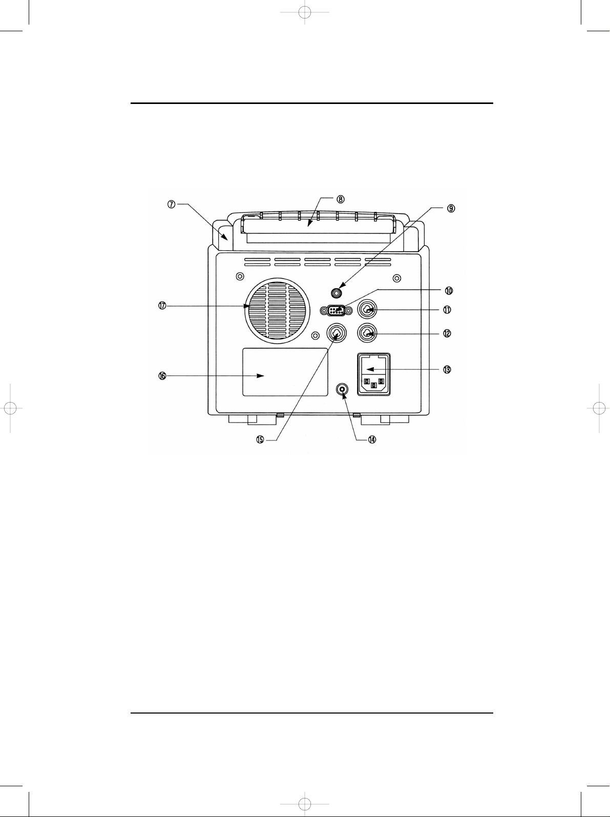
■■Rear panel
(7) Rear cover
(8) Lift handle
(9) Event marker socket
: Connect Event Marker to this connector.
(10) Serial port
: Connect PC to this connector using by supplied cable. (option)
(11) DOP I transducer port
: Connect DOP probe to this connector.
It is displayed to FHR I overlay part.
(12) DOP Ⅱtransducer port
: Connect DOP probe to this connector.
It is displayed to FHR I overlay part.
Mark
RS-232C DCP
UC
IFM500(영문) 1904.2.3 9:48 PM 페이지14 001 pdf-in
Product Description
15
IFM-500
(13) Power inlet
(14) Protect ground
(15) Tocotransducer port
: Connect UC probe to this connector.
(16) Main label
(17) Speaker
Auxiliary equipment connected to the system interface must be certified according to the
respective IEC standard (e.q. IEC 950 for data processing equipment configurations shall comply
with the system standard IEC 60601-1.) Everybody who connects additional equipment to the
signal input part or signal output part configures a medical system, and therefore responsible that
the system complies with the require-ments of the system standard IEC 60601- 1. If in doubt,
consult the technical service department of your local representative.
To avoid electrical shock, do not open the cabinet. Refer servicing to qualified personnel only.
Da Gefahr eines elektrischen Schlags besteht, darf das Gehause nicht geoffnet werden.
Uberlassen Sie Wartungsabeiten stets einem Fachmann.
Pour eviter tout risque d’ electroncution, ne pas ouvrir le coffret. Confier l’ entretien uniquement
a un personnel qualifie.
IFM500(영문) 1904.2.3 9:48 PM 페이지15 001 pdf-in
Table of contents
Other Bionics Medical Equipment manuals


Popular Medical Equipment manuals by other brands


Getinge
Getinge Arjohuntleigh Nimbus 3 Professional Instructions for use

Mettler Electronics
Mettler Electronics Sonicator 730 Maintenance manual

Pressalit Care
Pressalit Care R1100 Mounting instruction

Denas MS
Denas MS DENAS-T operating manual

bort medical
bort medical ActiveColor quick guide

AccuVein
AccuVein AV400 user manual


