BIOS AP DVPro DVT12T3 User manual

DVPro High Performance Storage System User Manual
----------------------------------------------------------------------------
DVT12T3
Thunderbolt 3
User Manual
Ver 1.0
----------------------------------------------------------------------------


Safety Warning
To avoid injury oneself, please heed the following instructions.
■The following indications explain the degree of physical danger possible by ignoring the proper usage
directions.
■The various types of warning symbols are listed in the following picture.
This symbol means that you should pay extra caution.
This symbol indicates something you absolutely must not do.
This symbol indicates something you must do.
WARNING
This symbol and waning is used to indicate sections
that may result in a serious injury or even death.
This symbol and caution is used to indicate
sections that only pose a risk of minor injury or
physical damage.
CAUTION
M

BIOS AP Inc.
-1-
Precautions
This user manual contains features, functions, setup, and warnings, so please read this manual prior to use
the product.
・The information in this manual is subject to change without prior notice.
・It is prohibited to reproduce any part of this manual in any form or by any means without prior written
permission of the manufacturer and the author.
・Manufacturer assumes no liability or responsibility for any errors that may appear in this manual.
・Regarding any question there might be, please contact vender whom you purchased the unit from.
・All trademarks stated in this manual belong to the properties of their respective owners.

DVT12T3
-2-
‥‥‥‥‥‥‥‥‥‥‥‥‥‥‥‥‥‥‥‥‥‥‥‥‥‥‥‥‥‥‥‥‥‥‥‥‥‥‥‥‥‥‥‥‥‥‥‥
‥‥‥‥‥‥‥‥‥‥‥‥‥‥‥‥‥‥‥‥‥‥‥‥‥‥‥‥‥‥‥‥‥‥‥‥‥‥‥‥‥‥‥‥‥‥‥‥
‥‥‥‥‥‥‥‥‥‥‥‥‥‥‥‥‥‥‥‥‥‥‥‥‥‥‥‥‥‥‥‥‥‥‥‥‥‥‥‥‥‥‥‥‥‥‥‥
‥‥‥‥‥‥‥‥‥‥‥‥‥‥‥‥‥‥‥‥‥‥‥‥‥‥‥‥‥‥‥‥‥‥‥‥‥‥‥‥‥‥‥‥‥‥‥‥
‥‥‥‥‥‥‥‥‥‥‥‥‥‥‥‥‥‥‥‥‥‥‥‥‥‥‥‥‥‥‥‥‥‥‥‥‥‥‥‥‥‥‥‥‥‥‥‥
‥‥‥‥‥‥‥‥‥‥‥‥‥‥‥‥‥‥‥‥‥‥‥‥‥‥‥‥‥‥‥‥‥‥‥‥‥‥‥‥‥‥‥‥‥‥‥‥
‥‥‥‥‥‥‥‥‥‥‥‥‥‥‥‥‥‥‥‥‥‥‥‥‥‥‥‥‥‥‥‥‥‥‥‥‥‥‥‥‥‥‥‥‥‥‥‥
‥‥‥‥‥‥‥‥‥‥‥‥‥‥‥‥‥‥‥‥‥‥‥‥‥‥‥‥‥‥‥‥‥‥‥‥‥‥‥‥‥‥‥‥‥‥‥‥
‥‥‥‥‥‥‥‥‥‥‥‥‥‥‥‥‥‥‥‥‥‥‥‥‥‥‥‥‥‥‥‥‥‥‥‥‥‥‥‥‥‥‥‥‥‥‥‥
‥‥‥‥‥‥‥‥‥‥‥‥‥‥‥‥‥‥‥‥‥‥‥‥‥‥‥‥‥‥‥‥‥‥‥‥‥‥‥‥‥‥‥‥‥‥‥‥
‥‥‥‥‥‥‥‥‥‥‥‥‥‥‥‥‥‥‥‥‥‥‥‥‥‥‥‥‥‥‥‥‥‥‥‥‥‥‥‥‥‥‥‥‥‥‥‥
‥‥‥‥‥‥‥‥‥‥‥‥‥‥‥‥‥‥‥‥‥‥‥‥‥‥‥‥‥‥‥‥‥‥‥‥‥‥‥‥‥‥‥‥‥‥‥‥
‥‥‥‥‥‥‥‥‥‥‥‥‥‥‥‥‥‥‥‥‥‥‥‥‥‥‥‥‥‥‥‥‥‥‥‥‥‥‥‥‥‥‥‥‥‥‥‥
‥‥‥‥‥‥‥‥‥‥‥‥‥‥‥‥‥‥‥‥‥‥‥‥‥‥‥‥‥‥‥‥‥‥‥‥‥‥‥‥‥‥‥‥‥‥‥‥
‥‥‥‥‥‥‥‥‥‥‥‥‥‥‥‥‥‥‥‥‥‥‥‥‥‥‥‥‥‥‥‥‥‥‥‥‥‥‥‥‥‥‥‥‥‥‥‥
‥‥‥‥‥‥‥‥‥‥‥‥‥‥‥‥‥‥‥‥‥‥‥‥‥‥‥‥‥‥‥‥‥‥‥‥‥‥‥‥‥‥‥‥‥‥‥‥
‥‥‥‥‥‥‥‥‥‥‥‥‥‥‥‥‥‥‥‥‥‥‥‥‥‥‥‥‥‥‥‥‥‥‥‥‥‥‥‥‥‥‥‥‥‥‥‥
‥‥‥‥‥‥‥‥‥‥‥‥‥‥‥‥‥‥‥‥‥‥‥‥‥‥‥‥‥‥‥‥‥‥‥‥‥‥‥‥‥‥‥‥‥‥‥‥
‥‥‥‥‥‥‥‥‥‥‥‥‥‥‥‥‥‥‥‥‥‥‥‥‥‥‥‥‥‥‥‥‥‥‥‥‥‥‥‥‥‥‥‥‥‥‥‥
‥‥‥‥‥‥‥‥‥‥‥‥‥‥‥‥‥‥‥‥‥‥‥‥‥‥‥‥‥‥‥‥‥‥‥‥‥‥‥‥‥‥‥‥‥‥‥‥
‥‥‥‥‥‥‥‥‥‥‥‥‥‥‥‥‥‥‥‥‥‥‥‥‥‥‥‥‥‥‥‥‥‥‥‥‥‥‥‥‥‥‥‥‥‥‥‥
‥‥‥‥‥‥‥‥‥‥‥‥‥‥‥‥‥‥‥‥‥‥‥‥‥‥‥‥‥‥‥‥‥‥‥‥‥‥‥‥‥‥‥‥‥‥‥‥
‥‥‥‥‥‥‥‥‥‥‥‥‥‥‥‥‥‥‥‥‥‥‥‥‥‥‥‥‥‥‥‥‥‥‥‥‥‥‥‥‥‥‥‥‥‥‥‥
‥‥‥‥‥‥‥‥‥‥‥‥‥‥‥‥‥‥‥‥‥‥‥‥‥‥‥‥‥‥‥‥‥‥‥‥‥‥‥‥‥‥‥‥‥‥‥‥
‥‥‥‥‥‥‥‥‥‥‥‥‥‥‥‥‥‥‥‥‥‥‥‥‥‥‥‥‥‥‥‥‥‥‥‥‥‥‥‥‥‥‥‥‥‥‥‥

BIOS AP Inc.
-3-
Table of Contents
Precautions..........................................................................................................................1
Table of Contents ................................................................................................................3
Chapter 1. Outline.............................................................................................................4
1.1. Features ............................................................................................................................................. 4
1.2. Functions............................................................................................................................................ 4
1.3. Packing Contents ............................................................................................................................... 5
1.4. Hardware Components ...................................................................................................................... 5
1.5. Power On/Off Mode............................................................................................................................ 8
1.6. Connection ......................................................................................................................................... 8
1.5.1 Cascade 2nd device.................................................................................................................. 8
1.5.2Power Delivery to Host or Device ............................................................................................ 8
Chapter 2. Setup and Monitor .........................................................................................11
2.1. Operation Overview...........................................................................................................................11
2.2. Introduction of Parameters Setup .....................................................................................................11
2.3. Front Panel LCD Toggle rolling setup flowchart ............................................................................... 12
2.4. Meanings of Parameters .................................................................................................................. 12
2.5. Prameter Browsing and Network Address Configuration from Front Panel Operation.................... 15
2.5.1 Method to setup Ethernet IP address by front panel.............................................................. 15
2.5.2 Browse Current Parameters................................................................................................... 16
2.5.3 Real-time Transfer Speed and Enclosure Status Information................................................ 16
2.6 Web-based GUI for Parameter Setup and Status Monitor............................................................... 19
2.6.1 Main Screen of GUI................................................................................................................ 19
2.6.2 Introduction of Monitor Mode.................................................................................................. 20
2.6.3 Management Mode Login....................................................................................................... 23
2.6.4 Setup of email notification...................................................................................................... 25
2.6.5 Mail Format............................................................................................................................. 26
2.6.6 Conditions of Mail Notification................................................................................................ 27
2.6.7 SNMP Setup........................................................................................................................... 27
2.6.8 Additional Parameters Setup.................................................................................................. 29
2.7 Setup Mode (Array Parameters Setting) .......................................................................................... 30
2.8 Host LAN Configuration ................................................................................................................... 38
2.8.1 IP Setup for Windows............................................................................................................. 38
2.8.2 IP Setup for Linux................................................................................................................... 40
2.8.3 IP Setup for MAC OS X.......................................................................................................... 41
Appendix A –Error Message shown on LCD.....................................................................44

DVT12T3
-4-
Chapter 1. Outline
1.1. Features
⚫Support up to 12 Hot-Swappable SATA HDD (Hard Disk Drive)
⚫Support different RAID modes including RAID 6, 5, 0,10
⚫Thunderbolt 3 (40Gbps) backward compatible
⚫Revertible Type-C™connector
⚫Power Delivery up to 27Watt computer charge
⚫Real time FPGA RAID 6 Engine with parity generation and DMA Controller
⚫Automatic Rebuild at adjustable Rebuild Rate
⚫HDD Patrol and spot error recovery
⚫LCD and keypad operation for status monitoring and system configuration
⚫Web GUI status monitoring and system configuration
⚫Support Mac OS 10.6 or above and Windows 10 (Driver needed)
1.2. Functions
⚫Adjustable Rebuild Priority
⚫Adjustable hard disk patrol for bad sector recovery
⚫Temperature sensing Fan Speed Control
⚫Real-time host and disk speed monitoring on LCD
⚫Event Display on LCD, Buzzer Alarm
⚫Fault LED Indication for Drive and Controller
⚫Email Notification Support
⚫SNMP notification
⚫ATX-like power on/off

BIOS AP Inc.
-5-
1.3. Packing Contents
DVT12T3: Storage system
AC Power Cord: 1 piece, USA/Japan applicable unless specified
Screws: 50 pcs of screws for drive installation
Quick Installation Guide: A quick guide for drive installation and introduction
Host cable: Thunderbolt 3 Type-C™cable 5A 2M
Type-C cable-tie: to fix the Type-C cable tightly on chassis (optional use)
1.4. Hardware Components
< Front View>
⑧
①
④
⑥
⑦
②
③
⑤
DVT12T3
-6-
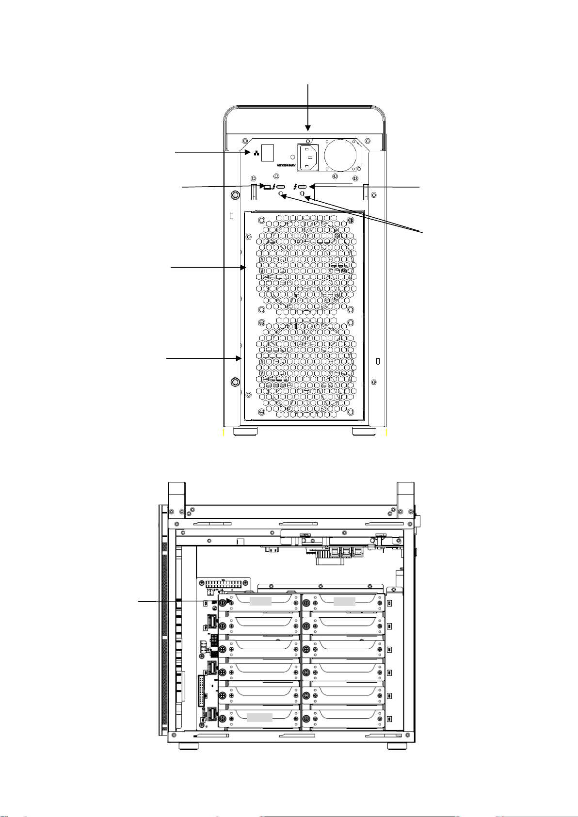
< Rear View >
< Side View >
⑨
⑩
⑪
⑬
⑭
⑮
⑫
⑯
Disk 0
Disk 1
Disk 10

BIOS AP Inc.
-7-
No
Name
Function Explanation
①
POWER Button
Power ON /OFF (Press the button for 4 seconds to turn off)
②
HDD Access / FAIL
Bi-color LED
Blue On: Drive asserted, Flash upon access;
Red ON: indicates an error
When「RAID-x RECOVERING 0%」shown on LCD, the FAIL LED on
means the HDD is under rebuilding
③
POWER LED
Blue: Power ON LED indicator
④
ACCESS LED
Green: Controller Access LED indicator
⑤
FAIL LED
Red: A controller error LED indicator
⑥
MODE Button
1)Parameter Initialization(Power on Initialization)
2)Configure parameters 「See Chapter 2」
3)Stop buzzer alarm(Buzzer stopped immediately by pushing one
time)
⑦
SELECT Button
Setup Parameter
⑧
LCD Display
Message display screen. Show status of the system
and parameters while doing configuration
⑨
Power Input
AC Inlet (100V-220V auto switching)
⑩
Ethernet Port
RJ45 Fast Ethernet port for Web GUI management
⑪
Type-C (Device)
Downstream port for Daisy chain to another device
⑫
Type-C(Host)
Upstream port to Thunderbolt Host
⑬
Fan Module
Fan 1
⑭
Fan Module
Fan 2
⑮
Cable Tie Holes
Insertion hole of Type-C cable-tie wrap
⑯
Drive Module
Disk Drive module 0 (to 11) Upper left is number 0, and right is 1

DVT12T3
-8-
1.5. Power On/Off Mode
Turn on the storage by press power button once. Turn off the storage by press and hold the button more than
four seconds. Blue LED on power button can be identified as its status.
There are two power recovery mode designed in this storage - Always Off and Last State
Always Off (Default, Blue LED light on): The storage will remain off after power recovery.
Last State (Blue LED flash): The storage will be On or Off depending on the last state before power outage.
Users can switch between these two modes by double click the power button quickly during operation. The
new mode will not be effective till next power cycle.
1.6. Connection
<Beginning of configuration>
Most of devices should have disk drives inserted and pre-configured with its default setting. The
default configuration is 12 drives with RAID 6.
<Steps for host connection>
Assume the unit was pre-configured with drives and RAID, if not please refer to Chapter 2 or Quick
Installation Guide for RAID configuration and drive installation
①Power on the storage and check if LCD showed “RAID 6 Normal”
②Connect Thunderbolt 3 cable from host PC to the storage (Left hand port with a computer mark) A
2M long Thunderbolt 3 Type-C cable is included in the package.
③Power on the host system.
④Host system should detect the disk within seconds. The unit is ready for use. Refer to chapter 3 for
disk format if you are not familiar with.
If necessary to change RAID configuration, web-based management is recommended. Please read
Chapter 2 for instructions.
1.5.1 Cascade 2nd device
Single thunderbolt host port can support up to six Thunderbolt compatible devices. The right-hand Type-C
port of DVT12T3 is used to cascade the next device. The device could be another certified Thunderbolt
device or USB device.
1.5.2 Power Delivery to Host or Device
The DVT12T3 supports USB Power Delivery 2.0 with 5V or 9V maximum 3A output. The Type-C host port
supports up to 27Watt* charge to host computer. The Type-C Device port can supply up to 15Watt power to
the attached (bus powered) device.

BIOS AP Inc.
-9-
*Host charge support depends on the host connected. Not every host port can be charged via Type-C. For
details, please refer to the user manual of host computer.

DVT12T3
-10 -
‥‥‥‥‥‥‥‥‥‥‥‥‥‥‥‥‥‥‥‥‥‥‥‥‥‥‥‥‥‥‥‥‥‥‥‥‥‥‥‥‥‥‥‥‥‥‥‥
‥‥‥‥‥‥‥‥‥‥‥‥‥‥‥‥‥‥‥‥‥‥‥‥‥‥‥‥‥‥‥‥‥‥‥‥‥‥‥‥‥‥‥‥‥‥‥‥
‥‥‥‥‥‥‥‥‥‥‥‥‥‥‥‥‥‥‥‥‥‥‥‥‥‥‥‥‥‥‥‥‥‥‥‥‥‥‥‥‥‥‥‥‥‥‥‥
‥‥‥‥‥‥‥‥‥‥‥‥‥‥‥‥‥‥‥‥‥‥‥‥‥‥‥‥‥‥‥‥‥‥‥‥‥‥‥‥‥‥‥‥‥‥‥‥
‥‥‥‥‥‥‥‥‥‥‥‥‥‥‥‥‥‥‥‥‥‥‥‥‥‥‥‥‥‥‥‥‥‥‥‥‥‥‥‥‥‥‥‥‥‥‥‥
‥‥‥‥‥‥‥‥‥‥‥‥‥‥‥‥‥‥‥‥‥‥‥‥‥‥‥‥‥‥‥‥‥‥‥‥‥‥‥‥‥‥‥‥‥‥‥‥
‥‥‥‥‥‥‥‥‥‥‥‥‥‥‥‥‥‥‥‥‥‥‥‥‥‥‥‥‥‥‥‥‥‥‥‥‥‥‥‥‥‥‥‥‥‥‥‥
‥‥‥‥‥‥‥‥‥‥‥‥‥‥‥‥‥‥‥‥‥‥‥‥‥‥‥‥‥‥‥‥‥‥‥‥‥‥‥‥‥‥‥‥‥‥‥‥
‥‥‥‥‥‥‥‥‥‥‥‥‥‥‥‥‥‥‥‥‥‥‥‥‥‥‥‥‥‥‥‥‥‥‥‥‥‥‥‥‥‥‥‥‥‥‥‥
‥‥‥‥‥‥‥‥‥‥‥‥‥‥‥‥‥‥‥‥‥‥‥‥‥‥‥‥‥‥‥‥‥‥‥‥‥‥‥‥‥‥‥‥‥‥‥‥
‥‥‥‥‥‥‥‥‥‥‥‥‥‥‥‥‥‥‥‥‥‥‥‥‥‥‥‥‥‥‥‥‥‥‥‥‥‥‥‥‥‥‥‥‥‥‥‥
‥‥‥‥‥‥‥‥‥‥‥‥‥‥‥‥‥‥‥‥‥‥‥‥‥‥‥‥‥‥‥‥‥‥‥‥‥‥‥‥‥‥‥‥‥‥‥‥
‥‥‥‥‥‥‥‥‥‥‥‥‥‥‥‥‥‥‥‥‥‥‥‥‥‥‥‥‥‥‥‥‥‥‥‥‥‥‥‥‥‥‥‥‥‥‥‥
‥‥‥‥‥‥‥‥‥‥‥‥‥‥‥‥‥‥‥‥‥‥‥‥‥‥‥‥‥‥‥‥‥‥‥‥‥‥‥‥‥‥‥‥‥‥‥‥
‥‥‥‥‥‥‥‥‥‥‥‥‥‥‥‥‥‥‥‥‥‥‥‥‥‥‥‥‥‥‥‥‥‥‥‥‥‥‥‥‥‥‥‥‥‥‥‥
‥‥‥‥‥‥‥‥‥‥‥‥‥‥‥‥‥‥‥‥‥‥‥‥‥‥‥‥‥‥‥‥‥‥‥‥‥‥‥‥‥‥‥‥‥‥‥‥
‥‥‥‥‥‥‥‥‥‥‥‥‥‥‥‥‥‥‥‥‥‥‥‥‥‥‥‥‥‥‥‥‥‥‥‥‥‥‥‥‥‥‥‥‥‥‥‥
‥‥‥‥‥‥‥‥‥‥‥‥‥‥‥‥‥‥‥‥‥‥‥‥‥‥‥‥‥‥‥‥‥‥‥‥‥‥‥‥‥‥‥‥‥‥‥‥
‥‥‥‥‥‥‥‥‥‥‥‥‥‥‥‥‥‥‥‥‥‥‥‥‥‥‥‥‥‥‥‥‥‥‥‥‥‥‥‥‥‥‥‥‥‥‥‥
‥‥‥‥‥‥‥‥‥‥‥‥‥‥‥‥‥‥‥‥‥‥‥‥‥‥‥‥‥‥‥‥‥‥‥‥‥‥‥‥‥‥‥‥‥‥‥‥
‥‥‥‥‥‥‥‥‥‥‥‥‥‥‥‥‥‥‥‥‥‥‥‥‥‥‥‥‥‥‥‥‥‥‥‥‥‥‥‥‥‥‥‥‥‥‥‥
‥‥‥‥‥‥‥‥‥‥‥‥‥‥‥‥‥‥‥‥‥‥‥‥‥‥‥‥‥‥‥‥‥‥‥‥‥‥‥‥‥‥‥‥‥‥‥‥
‥‥‥‥‥‥‥‥‥‥‥‥‥‥‥‥‥‥‥‥‥‥‥‥‥‥‥‥‥‥‥‥‥‥‥‥‥‥‥‥‥‥‥‥‥‥‥‥
‥‥‥‥‥‥‥‥‥‥‥‥‥‥‥‥‥‥‥‥‥‥‥‥‥‥‥‥‥‥‥‥‥‥‥‥‥‥‥‥‥‥‥‥‥‥‥‥
‥‥‥‥‥‥‥‥‥‥‥‥‥‥‥‥‥‥‥‥‥‥‥‥‥‥‥‥‥‥‥‥‥‥‥‥‥‥‥‥‥‥‥‥‥‥‥‥

BIOS AP Inc.
-11 -
Chapter 2. Setup and Monitor
2.1. Operation Overview
To simplify the process of setup, DVPro is designed to support necessary configuration from front panel
LCD and button operation. The default RAID level is RAID6 for highest reliability. To prevent malfunction,
parameters cannot be changed at regular operation (Monitor) mode. The device needs to be in
Parameter Setup mode (Setup mode here after) for configuration. Under Monitor mode, LCD will show
“RAID 6 Normal”as long as no attention event occurred. Any error identified, or status changed will be
dynamically reflected to associated indicators such as LED light, buzzer alarm, and LCD display etc. Only
if you wanted to change parameter setting, should anyone choose to turn the device onto Setup mode.
DVPro needs to be re-booted for Mode change to avoid mis-operation from front panel.
Critical parameters including Disk size, number of drives, and RAID mode should have been
pre-configured with hard drives installed. If not, you will need to properly configure them before any
operation. Default parameters, if any, are followed with “*” sign. Front LCD panel acts as a short path for
device configuration yet Web GUI is more convenient and recommended to be used.
2.2. Introduction of Parameters Setup
This section explains the general parameters setup process.
To start with new configuration, the system has to be in Setup mode. Use one hand to press and hold
both “Mode”and “Select”buttons on LCD panel, another hand to push power button turning on the
storage. “ARRAY PARAMETERS SETTING” will be displayed on front LCD indicating the system in
Setup mode. Buttons can be released after then.
ARRAY PARAMETERS
SETTING!
You can then start the modification of necessary parameters under Setup mode.
General usage of Buttons explained as below:
MODE Button: To rotate among configurable Parameter items
SELECT Button: Select and switch among parameter value
●Enter Parameters Setting mode
:MODE Button +SELECT Button + Power On
●Rotate among Setup items
:MODE Button
●Setup parameters
:SELECT Button
After any parameter modified, press both MODE and SELECT button at the same to save the change.
New configuration will be effective at next power on.
When you successfully save the change of parameters, you will see below message shown on LCD

DVT12T3
-12 -
POWER DOWN
PLEASE!
You can then shut down and turn the storage back on.
If you power down the storage without applying Save operation, parameters will remain unchanged.
● Save parameters
①MODE +SELECT Button (Save)
②Shutdown and power on (New parameters effective)
● Cancel the change
Power off while doing change
If any of Critical Parameters (RAID mode, Disk size, Drive mode) was changed, hold down the
Mode button at power on at the same time for system initialization. (This action will set the device to
its normal status and abort Rebuild operation if any.) After power on, a “RAID-n NORMAL”will be
displayed on LCD.
RAID-6
NORMAL
2.3. Front Panel LCD Toggle rolling setup flowchart
ARRAY PARAMETERS
SETTING!
:Initial Display
↓
Disk Size Setup
:Hard Disk Capacity Setup
↓
RAID MODE Setup
:RAID Mode Setup
↓
DRIVE MODE Setup
:Number of Drive Setup
↓
RECOVERY MODE Setup
:Priority of RAID Rebuild
↓
System Patrol MODE
Setup
:HDD disk surface scan schedule
↓
Fan Speed Temperature
:Fan Speed Control set up
2.4. Meanings of Parameters
This section explains each RAID parameter and its associated function.

BIOS AP Inc.
-13 -
Ps. Strongly recommend users to record parameters before change. You can follow the
method described on「Parameter Confirmation」section to read its value.
⚫Disk Size
DISK Size
xxB
Disk size will not be automatically detected and should be manually configured. The size will be applied to
all drives. Actual disk capacities should be larger than this configured size.
A drive size bigger than supported listing will be added in future firmware upgrade. Please check our website
for new firmware.
Parameter
Function
Memo
Test 1GB
Set DISK Size as 1GB (Test only)
1TB, 2TB, 3TB, 4TB,
5TB, 6TB, 7TB, 8TB,
10TB, 12TB
Set Disk Size as the number
● Please do not change the default setting
If actual drive size was smaller than setup value, error such as「ONE DOWN
L」,「SYSTEM DOWN L」will occur and buzzer will be fired.
⚫RAID Mode Setup
RAID MODE
RAID-6
RAID mode selection, supported RAID MODEs are
RAID 6, RAID 5, RAID 0, RAID 10
RAID10 works as a pair of ‘Drive 0, 1’ ‘Drive 2, 3’, ‘Drive 4, 5’ etc.
⚫DRIVE Mode Setup
DRIVE MODE
12*
The product supports 12 SATA drives. Minimum number of drives depend on RAID level. If you needed
information of RAID mode, minimum drive or compatible drive models, please contact your vendor or us
for support.
⚫Recovery Rate Setup
CAUTION
M

DVT12T3
-14 -
RECOVER RATE
5Min. /GB
Recovery (Rebuild) operations utilize free time between host data access without interrupting the current
host application.
Therefore data read/write priority can be adjusted through different recovery rate setting.
User can choose the timing to execute recovery operations as below.
Parameter
Function
Memo
RECOVER
WAIT
TIME 0 Sec
Recovery request will be processed immediately between host
commands. Recovery will always be processed therefore host
access will be slow down. Select this mode if you want the
recovery have high priority.
RECOVER
WAIT
TIME 0.1 Sec
Continuous host commands will be processed first. Recovery
operation will be taken care when the interval between host
commands longer than 0.1 sec. The following host command has
to wait till one recovery task completed except READ/WRITE or
READ Cache command which will be executed immediately.
Default
RECOVER
WAIT
TIME 1 Sec
This can be used when host access are not concentrated.
The wait interval following the last host command is 1 sec. On this
mode, the recovery operation will not be processed if the host
commands are continuous with less than 1 sec internal.
RECOVER
WAIT
TIME 10 Sec
Usually this should not be used.
Probably this mode can be applied if there is very little host
access.
RECOVER
RATE
2Min./GB
5Min./GB
10Min./GB
20Min./GB
This is to assign the recovery time for 1GB capacity despite of
interval to wait between host commands.
There is possibility 1GB recovery cannot be completed
within assigned interval.
⚫Patrol Time Setup
SYSTEM PATROL
30 DAYS/CYCLE
10S, 5S, 3S, 5 DAYS/CYCLE,
10 DAYS/CYCLE, 20 DAYS/CYCLE,
30 DAYS/CYCLE*
This parameter is to specify the period of doing patrol. You can setup 「10S」,「5S」,「3S」to perform
one time patrol or you can setup「5 DAYS/CYCLE」,「10 DAYS/CYCLE」,「20 DAYS/CYCLE」,「30
DAYS/CYCLE」to perform whole capacity patrol.
The length of one Patrol depends on this setting and the Buffer Segment Size.
System Patrol
30 Days/Cycle
Calculate of the whole LUN size and schedule patrol all disk in 30
days cycle
Default
System Patrol
5/10/20
Days/Cycle
Calculate of the whole LUN size and schedule patrol all disk in
5/10/20 days cycle
System Patrol
System Patrol will be started if interval of host commands is larger

BIOS AP Inc.
-15 -
Wait
10S/5S/3S
than 10S/5S/3S
⚫Fan speed control temperature
Set up temperature criteria for System fan speed control
FAN SPEED TEMP
45 deg. C
20, 30, 35, 40, 45*, 50, 55, 60 deg C
When the detected temperature (RAID Core chip) is higher than the FAN SPEED TEMP, the fan will
be turned into high speed. The pre-set temperature is 45 degree and should not be changed.
2.5. Prameter Browsing and Network Address Configuration
from Front Panel Operation
You can change network parameters such as Management IP addresses described below by front panel
operation. Nevertheless, Web UI is usually recommended for such requirement if accessible.
PS)Please take a memo before you apply to change the setting. Default IP (IPv4) address
is 192.168.50.210. Subnet mask is 255.255.255.0
2.5.1 Method to setup Ethernet IP address by front panel
In case necessary to configure IP address by front panel, you can follow below steps to set it up. It is
recommended to change IP address through Web GUI.
1.Press both Mode and Select buttons, power up to enter Setting mode.
ARRAY PARAMETERS
SETTING!
2.Press the SELECT button (instead of MODE to set up RAID operational parameters)
Firm ware is
Ver.x.xxx
Firmware version will be displayed
After then, press front Mode button to change network parameters. You will see current IP address
displayed on LCD as below
● IP Address Setup
IP Address
192.168.50.210
By pushing SELECT button, the IP Address will be increased from leftist digit.
The longer you hold the SELECT button, the faster the number is increased.
Push the MODE button to move to next field. (Again Management GUI is recommended)
● Address Mask Setup

DVT12T3
-16 -
Address Mask
255.255.255.0
This is to setup IP address mask same as IP setup. Use the same way to change address mask as
described above for IP address.
If you wanted to continuously change other parameters, you can keep pressing Mode button to roll
among other parameters. Or you can press MODE+SELECT button to save the change and restart
the storage to take new network parameters effective. Do not forget the save operation otherwise
selected parameters will not be changed.
2.5.2 Browse Current Parameters
Sometimes you will need to read and check current parameters on storage. You can press both MODE
and SELECT button on the front panel under Monitor mode. IP Address will first be shown at the beginning
and the parameter can be browsed among by pressing MODE button. All of parameters and its default
value are listed in below table for reference.
< Factory Default Setting > Customer can record major parameters in case necessary
Parameter
Default or Pre-set
Notes
Firmware
Firm ware is Ver. x.xxx
Information only for reference
Vendor ID
Vender ID is BIOS
Information only for reference
Model No
Product ID is DVT12T3
Information only for reference
Serial No
Serial No ID xxxxxxxx
Information only for reference
IP Address
192.168.50.210
For Management GUI access
Address Mask
255.255.255.0
For Management GUI access
RAID Mode
RAID MODE RAID-6
RAID-10 / RAID-6 / RAID-0 / RAID-5
DRIVE Mode
DRIVE MODE 12
3, 4, 5, 6, 7, 8, 9, 10, 11, 12
Disk Size
DISK size
Test1GB/1TB/2TB/3TB/4TB/5TB/6TB/7TB/8TB/10TB/12T
B
Recovery Wait
Time
0.1 Sec
0/ 0.1/1/10 Sec, 2Min/5 Min/10 Min/20 Min
System Patrol
30Days/Cycle
10S, 5S, 3S, 5/10/20 DAYS/CYCLE
Fan Speed Temp
45 Deg C
20, 30, 35, 40, 45, 50, 55, 60 Deg C
2.5.3 Real-time Transfer Speed and Enclosure Status Information
Front panel also provide extra features such as displaying real-time data transfer speed which could not
be found from Web GUI.
Check Real-time Host Transfer Speed
Press SELECT button twice under Monitor mode and LCD will show Host Rate = x.xx MB/s. A
“0.00MB/S” means there is no data access from host.

BIOS AP Inc.
-17 -
HOST
RATE = x.xxMB/S
Execute HDD Patrol
Press MODE button after host transfer speed check and LCD will show HDD patrol status.
Manually activate HDD patrol to scan possible error of disk drives.
The default setting is “Auto”. It means the drives automatically scanned when there is no data access.
Sometimes, users might want to scan disks immediately especially when drives are used after long time.
AUTO
HDD PATROL xx%
Users can change patrol mode to “FORCE HDD PATROL“ or possibly disable this feature by selecting
“NO HDD PATROL”. It is highly recommended to leave this as default to make sure drives patrol on going.
Check Operating Temperature
Keep pressing MODE button users can check temperature of RAID chip (Core)and system temperature
(Cont).
Cont. Temp 39.1oC
Core Temp 48.1oC
System fan speed
Keep pressing MODE button LCD will display system fan speed.
FAN1 1,920rpm
FAN2 1,875rpm
Check Real-time Disk Transfer Speed
To check each drive’s current transfer speed, keep pressing MODE button to browse real-time disk
transfer speed from channel 0 to channel 11. A “0.00MB/S” means there is no activity on the disk.
Channel 0
RATE = x.xxMB/S
Quick Overview of From Panel Button Operation
DVPro series button operations can be summarized as below
Other manuals for DVPro DVT12T3
1
Table of contents
Other BIOS AP Storage manuals


