BIOS AP DVPro DVT10T2 User manual
DVPro High Performance Storage System User Manual
----------------------------------------------------------------------------
DVT10T2
Thunderbolt™and eSATA6G / USB3
[ User Manual ]
Version 1.1
----------------------------------------------------------------------------


Safety Warning
In order to avoid injury oneself, please heed the following instructions.
■The following indications explain the degree of physical danger possible by ignoring the proper usage
directions.
■The various types of warning symbols are listed in the following picture.
This symbol means that you should pay extra attention.
This symbol indicates something you absolutely must not do.
This symbol indicates something you must do.
WARNING
This symbol and waning is used to indicate sections
that may result in a serious injury or even death.
This symbol and caution is used to indicate
sections that only pose a risk of minor injury or
physical damage.
CAUTION
M

BIOS AP Inc.
-1-
Precautions
This user manual contains features, functions, setup, and warnings, so please read this manual prior to use
our product.
・If any material in this manual is not clear, please contact vender whom you purchased the unit from.
・The information in this manual is subject to change without prior notice.
・It is prohibited to reproduce any part of this manual in any form or by any means without prior written
permission of the manufacturer and the author.
・Manufacturer assumes no liability or responsibility for any errors that may appear in this manual.
・All trademarks stated in this manual belong to the properties of their respective owners.

DVT10T2
-2-
‥‥‥‥‥‥‥‥‥‥‥‥‥‥‥‥‥‥‥‥‥‥‥‥‥‥‥‥‥‥‥‥‥‥‥‥‥‥‥‥‥‥‥‥‥‥‥‥
‥‥‥‥‥‥‥‥‥‥‥‥‥‥‥‥‥‥‥‥‥‥‥‥‥‥‥‥‥‥‥‥‥‥‥‥‥‥‥‥‥‥‥‥‥‥‥‥
‥‥‥‥‥‥‥‥‥‥‥‥‥‥‥‥‥‥‥‥‥‥‥‥‥‥‥‥‥‥‥‥‥‥‥‥‥‥‥‥‥‥‥‥‥‥‥‥
‥‥‥‥‥‥‥‥‥‥‥‥‥‥‥‥‥‥‥‥‥‥‥‥‥‥‥‥‥‥‥‥‥‥‥‥‥‥‥‥‥‥‥‥‥‥‥‥
‥‥‥‥‥‥‥‥‥‥‥‥‥‥‥‥‥‥‥‥‥‥‥‥‥‥‥‥‥‥‥‥‥‥‥‥‥‥‥‥‥‥‥‥‥‥‥‥
‥‥‥‥‥‥‥‥‥‥‥‥‥‥‥‥‥‥‥‥‥‥‥‥‥‥‥‥‥‥‥‥‥‥‥‥‥‥‥‥‥‥‥‥‥‥‥‥
‥‥‥‥‥‥‥‥‥‥‥‥‥‥‥‥‥‥‥‥‥‥‥‥‥‥‥‥‥‥‥‥‥‥‥‥‥‥‥‥‥‥‥‥‥‥‥‥
‥‥‥‥‥‥‥‥‥‥‥‥‥‥‥‥‥‥‥‥‥‥‥‥‥‥‥‥‥‥‥‥‥‥‥‥‥‥‥‥‥‥‥‥‥‥‥‥
‥‥‥‥‥‥‥‥‥‥‥‥‥‥‥‥‥‥‥‥‥‥‥‥‥‥‥‥‥‥‥‥‥‥‥‥‥‥‥‥‥‥‥‥‥‥‥‥
‥‥‥‥‥‥‥‥‥‥‥‥‥‥‥‥‥‥‥‥‥‥‥‥‥‥‥‥‥‥‥‥‥‥‥‥‥‥‥‥‥‥‥‥‥‥‥‥
‥‥‥‥‥‥‥‥‥‥‥‥‥‥‥‥‥‥‥‥‥‥‥‥‥‥‥‥‥‥‥‥‥‥‥‥‥‥‥‥‥‥‥‥‥‥‥‥
‥‥‥‥‥‥‥‥‥‥‥‥‥‥‥‥‥‥‥‥‥‥‥‥‥‥‥‥‥‥‥‥‥‥‥‥‥‥‥‥‥‥‥‥‥‥‥‥
‥‥‥‥‥‥‥‥‥‥‥‥‥‥‥‥‥‥‥‥‥‥‥‥‥‥‥‥‥‥‥‥‥‥‥‥‥‥‥‥‥‥‥‥‥‥‥‥
‥‥‥‥‥‥‥‥‥‥‥‥‥‥‥‥‥‥‥‥‥‥‥‥‥‥‥‥‥‥‥‥‥‥‥‥‥‥‥‥‥‥‥‥‥‥‥‥
‥‥‥‥‥‥‥‥‥‥‥‥‥‥‥‥‥‥‥‥‥‥‥‥‥‥‥‥‥‥‥‥‥‥‥‥‥‥‥‥‥‥‥‥‥‥‥‥
‥‥‥‥‥‥‥‥‥‥‥‥‥‥‥‥‥‥‥‥‥‥‥‥‥‥‥‥‥‥‥‥‥‥‥‥‥‥‥‥‥‥‥‥‥‥‥‥
‥‥‥‥‥‥‥‥‥‥‥‥‥‥‥‥‥‥‥‥‥‥‥‥‥‥‥‥‥‥‥‥‥‥‥‥‥‥‥‥‥‥‥‥‥‥‥‥
‥‥‥‥‥‥‥‥‥‥‥‥‥‥‥‥‥‥‥‥‥‥‥‥‥‥‥‥‥‥‥‥‥‥‥‥‥‥‥‥‥‥‥‥‥‥‥‥
‥‥‥‥‥‥‥‥‥‥‥‥‥‥‥‥‥‥‥‥‥‥‥‥‥‥‥‥‥‥‥‥‥‥‥‥‥‥‥‥‥‥‥‥‥‥‥‥
‥‥‥‥‥‥‥‥‥‥‥‥‥‥‥‥‥‥‥‥‥‥‥‥‥‥‥‥‥‥‥‥‥‥‥‥‥‥‥‥‥‥‥‥‥‥‥‥
‥‥‥‥‥‥‥‥‥‥‥‥‥‥‥‥‥‥‥‥‥‥‥‥‥‥‥‥‥‥‥‥‥‥‥‥‥‥‥‥‥‥‥‥‥‥‥‥
‥‥‥‥‥‥‥‥‥‥‥‥‥‥‥‥‥‥‥‥‥‥‥‥‥‥‥‥‥‥‥‥‥‥‥‥‥‥‥‥‥‥‥‥‥‥‥‥
‥‥‥‥‥‥‥‥‥‥‥‥‥‥‥‥‥‥‥‥‥‥‥‥‥‥‥‥‥‥‥‥‥‥‥‥‥‥‥‥‥‥‥‥‥‥‥‥
‥‥‥‥‥‥‥‥‥‥‥‥‥‥‥‥‥‥‥‥‥‥‥‥‥‥‥‥‥‥‥‥‥‥‥‥‥‥‥‥‥‥‥‥‥‥‥‥
‥‥‥‥‥‥‥‥‥‥‥‥‥‥‥‥‥‥‥‥‥‥‥‥‥‥‥‥‥‥‥‥‥‥‥‥‥‥‥‥‥‥‥‥‥‥‥‥

BIOS AP Inc.
-3-
Table of Contents
Precautions..........................................................................................................................1
Table of Contents ................................................................................................................3
Chapter 1. Outline.............................................................................................................4
1.1. Features ............................................................................................................................................. 4
1.2. Functions............................................................................................................................................ 4
1.3. Packing Contents ............................................................................................................................... 5
1.4. Hardware Components ...................................................................................................................... 5
1.5. Connection and Quick Host Selection................................................................................................ 8
Chapter 2. Setup and Monitor .........................................................................................12
2.1. Operation Overview.......................................................................................................................... 12
2.2. Introduction of Parameters Setup .................................................................................................... 12
2.3. Front Panel LCD Toggle rolling setup flowchart............................................................................... 13
2.4. RAID Operational Parameters ......................................................................................................... 14
2.5. Product Information and Background Parameters........................................................................... 20
2.5.1. Method to setup background parameters........................................................................... 21
2.5.2. Parameter Confirmation...................................................................................................... 27
2.6. Web-based Monitor and Setup via Ethernet.................................................................................... 30
2.6.1 Main Screen of Web GUI ....................................................................................................... 31
2.6.2 Introduction of Monitor Mode.................................................................................................. 32
2.6.3 Management Mode Login....................................................................................................... 36
2.6.4 Setup of email notification...................................................................................................... 38
2.6.5 Mail Format............................................................................................................................. 39
2.6.6 Conditions of Mail Notification................................................................................................ 40
2.6.7 SNMP Setup........................................................................................................................... 40
2.6.8 Additional Parameters Setup.................................................................................................. 42
2.7. Setup Mode (Array Parameters Setting).......................................................................................... 43
2.8. Host LAN Configuration ................................................................................................................... 50
2.8.1. IP Setup for Windows......................................................................................................... 50
2.8.2. IP Setup for Linux............................................................................................................... 52
2.8.3. IP Setup for MAC OS X...................................................................................................... 53
Chapter 3 Format...............................................................................................................56
3.1. Linux................................................................................................................................................. 56
3.2. Windows 7........................................................................................................................................ 58
3.3. Mac OS® X ...................................................................................................................................... 64
Appendix A - MBR of different Operating Systems............................................................68
Appendix B –Error Message shown on LCD.....................................................................69

DVT10T2
-4-
Chapter 1. Outline
1.1.Features
●Support up to 10 Hot-Swappable SATA HDD (Hard Disk Drive)
● Support different RAID modes including RAID 6, RAID 5, RAID 3, RAID 1, RAID 0, RAID10
●Alternative host Interface: Thunderbolt 2.0(x2 port) eSATA3 (6Gbps) and USB 3.0 (5Gbps)
● Original FPGA RAID 6 Engine with real time parity generation and high speed DMA switching
● Spot error recovery greatly reduces HDD error and rebuild probability
●Automatic Rebuild at adjustable Rebuild Rate
● LCD and keypad operation for status monitoring and system configuration
● Web GUI status monitoring and system configuration
1.2.Functions
● Disk volume can possibly be accessed via different interface, Thunderbolt, eSATA or USB3
● Support two LUNs under eSATA and USB configuration or single LUN for Thunderbolt
● Configurable Write Cache Mode
● Data Read Ahead Size
● Write Retry Mode
● Buffer Segment Size Adjustment
● Multiple Sequential Streams List Size
● Time out Interval for Low Speed Drive Detection
● Drive Ready Waiting Time
● Cache Memory Check Interval
● HDD Patrol Time and Mode
<Auxiliary Functions>
● Data Transfer Speed Display on LCD (Each drive and host channel speed)
● Event Display on LCD, Buzzer Alarm
● Fault LED Indication for Drive and Controller
●Email Notification Support
● Web-based Status Monitor
● SNMP notification
BIOS AP Inc.
-5-
1.3.Packing Contents
DVT10T2: Storage system
AC Power Cord (USA spec only)
USB3 Cable: 1 meter, Type A to Type B
Thunderbolt 2 Cable: 1.5 meter or 2M depend (upon availability not selectable)
Screws: 50 pcs of screws and Quick Installation Guide
Quick installation guide (printed) (for HDD installation if applicable)
1.4.Hardware Components
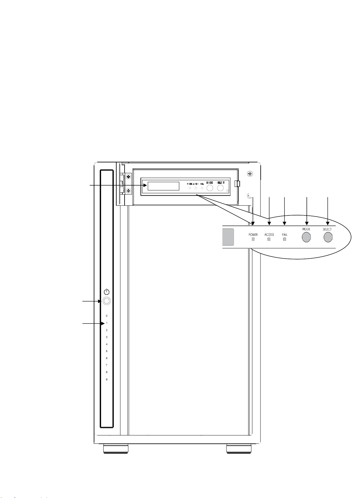
< Front View>
⑧
①
④
⑥
⑦
②
③
⑤
DVT10T2
-6-
⑱
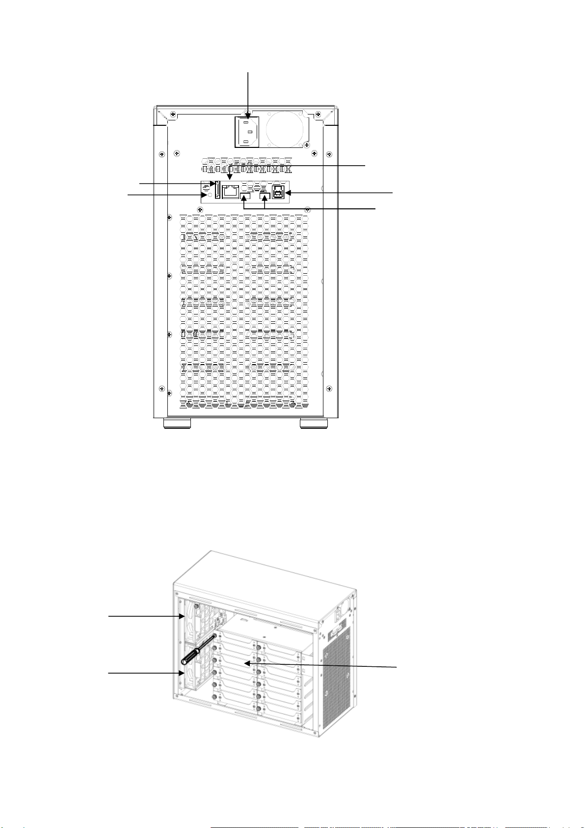
< Rear View >
< Side View >
⑨
⑩
⑫
⑪
⑯
⑰
⑬
⑭
⑮

BIOS AP Inc.
-7-
No.
Name
Function Explanation
①
POWER Button
Power ON /OFF Switch
②
HDD Access / FAIL
Bi-color LED
Blue On: Drive asserted, Flash upon access;
Red ON: indicates an error
When「RAID-x RECOVERING 0%」shown on LCD, the FAIL LED on
means the HDD is under rebuilding
③
POWER LED
Blue:Power ON LED indicator
④
ACCESS LED
Green:Controller Access LED indicator
⑤
FAIL LED
Red: A controller error LED indicator
⑥
MODE Button
1)Parameter Initialization(Power on Initialization)
2)Configure parameters 「See Chapter 2」
3)Stop buzzer alarm(Buzzer stopped immediately by pushing one
time)
⑦
SELECT Button
Setup Parameter
⑧
LCD Display
Message display screen. Show status of the system
and parameters while doing configuration
⑨
Power Input
AC Inlet (100V-220V auto switching)
⑩
eSATA3 Connector
eSATA 6G host connector
⑪
USB3 Connector
USB3 host connector (Type B)
⑫
Ethernet Port
RJ45 Fast Ethernet port for Web GUI management
⑬
Thunderbolt Connector
Thunderbolt 2 for host or cascade
⑭
Thunderbolt Connector
Thunderbolt 2 for host or cascade
⑮
Init Button
Power on Initialization
Host mode switch (Thunderbolt or USB+eSATA)
⑯
Fan Module
Fan 1
⑰
Fan Module
Fan 2
⑱
Drive Module
Disk Drive module 0 (to 9).Upper left one is number 0, and right is 1

DVT10T2
-8-
Default host interface setting is Thunderbolt. The USB3+eSATA
is not applicable while host mode is Thunderbolt vice versa.
Thunderbolt and USB+eSATA cannot be used at the same time.
Please make sure you have configured the storage with the host
interface you want to connect before starting.
Before you start any operation, please make sure HDDs are installed properly into the
DVT10T2 enclosure
An alarming beep sound will be turned on if right number of HDD module was not
installed properly
Please make sure number of drives, RAID mode, and disk size were configured correctly
before starting to host connection.
For drive installation, please refer to Quick Installation Guide.
1.5.Connection and Quick Host Selection
<Beginning of configuration>
Please go through the quick installation guide to configure the device if necessary. The default
configuration of the storage is Thunderbolt host with full LUN size working at RAID 6 protection.
<Steps for host connection>
1. Thunderbolt connection (Default)
While Thunderbolt is enabled, both eSATA and USB3 ports are forced to disable state. (Default
operation might be varied per request from vendors)
The following Mac models are Thunderbolt 2 capable:
MacBook Pro (Retina, Late 2013 and later)
Mac Pro (Late 2013)
iMac (Retina 5K, 27-inch, Late 2014)
Mac mini (Late 2014)
Mac Computers (Mac OS® X v10.9.x or above) are certified.
Windows 8.1 hosts might be applicable but not certified as our official support.
Only one LUN is visible to host for Thunderbolt connection.
Any of two Thunderbolt ports can be used as host or cascade.
①Simply connect Thunderbolt cable from host to the Thunderbolt port of storage device.

BIOS AP Inc.
-9-
②Power on the storage device before turning on host system. In case, the device was not properly
configured, then an alarm might be turned on. Turn off the device and turn it on again while pressing
Mode button. Release the Mode button to see if LCD showed RAID Normal.
③The pre-configured LUN drive should be identified and popped up on your host Desktop screen for
first time without partition. If not, you might need to check if the device Thunderbolt was chosen as
the host interface or not. You can also check if any Thunderbolt device was attached on Mac
system. Please refer to Chapter 3.3 for volume partition on Mac operating system.
2. USB3/eSATA dual connection
First, please make sure eSATA was configured as Host interface in device parameter. Default is
disabled. Please read Chapter 2 about how to change the host configuration. Most of operating systems
should work with eSATA and/or USB3 host without having to install any driver. For hosts with UASP
supported on USB3, we strongly recommend you to enable it for higher performance. eSATA is
supported by OS inbox AHCI driver.
Window 8 or later supports UASP on native Intel USB3 port.
Mac OS® X v10.7 or later supports UASP on its USB3 ports.
USB3 can be enabled or disabled only host mode is set to eSATA. If host mode is set to
Thunderbolt, USB3 will be forced to disable state no matter parameter selected. The storage device
supports division of the configured disk capacity into single or two LUNs by LUN Mode and LUN Size
parameters. The details explanation and configuration can be found on Section 2.3
Case 1: Single LUN connection (default, LUN Mode: Direct no bias, LUN Size: Full)
①Simply connect host eSATA* or USB3 cable (if enabled) from host to the associated port of storage
device. (USB3 cable is included but no eSATA cable inside the package)
②Power on the storage device before turning on host system. In case, the device was not properly
configured, then an alarm might be turned on. Turn off the device and turn it on again while pressing
Mode button. Release the Mode button to see if LCD showed RAID Normal.
③Host system should be able to detect the disk immediately. Sometimes due to the delay of hard disk
initialization, you might need to rescan the device to see if the device shown later. If you still could
not find the connected device, you might try to re-insert the eSATA or USB3 cable on device or host.
Please refer to Chapter 3 for volume partition on different operating systems.
*eSATA is treated as a SATA disk and can therefore be connected to SAS HBA, too.
Case 2: Dual LUNs connection –eSATA and USB 3 (LUN Mode: Swap no bias, LUN Size: 64GB+All)
①Simply connect both eSATA* and USB3 cables from host to the associated port of storage device
DVT10T2
-10 -
②Power on the storage device before turning on host system. In case, the device was not properly
configured, then an alarm might be turned on. Turn off the device and turn it on again while pressing
Mode button. Release the Mode button to see if LCD showed RAID Normal.
③Host system should be able to detect two disks immediately, one as ATA device and the other as
USB device. If not, be sure to make sure parameter “LUN Mode”set as “Swap no bias”. For
example LUN Size is set to “64GB+ALL”, eSATA disk size will be 64GB and the rest of capacity will
be mapped to USB3 disk.
④To change host configuration, web-based management is recommended. Please read Chapter 2 for
necessary instructions.
Do not connect both USB3 and eSATA to the host at the same
time while LUN Mode is set to “Direct no bias”. This would cause
disk data corruption even it might not happen immediately.
3. Quick Switch between Host Interface
You can always configure the host interface mode through web GUI or LCD operation. For details, please
refer to Chaper 2. Starting from firmware ped101, we added a quick switch by using “INIT”button at the rear
panel. The location of “Init”button can be found at rear I/O besides eSATA connector.
Please do NOT switch the host interface while accessing is ongoing
You might want to unplug host connection first before switching mode
The storage was shipped with Thunderbolt host default.
①At normal operation, upper right corner of front LCD with “T” indicates host interface set to
Thunderbolt
②Press the INIT button about 3 seconds, then Buzzer will be alarmed shortly.At the same time
LCD will temporary show below to indicate the host transition.
③After releasing INIT button, upper right corner of LCD will show “U”indicating host is set as
USB3.0/eSATA.
RAID-6 T
NORMAL
Operation mode
To USB3/eSATA
RAID-6 U
NORMAL

BIOS AP Inc.
-11 -
④Under USB3/eSATA host mode, Repeat Step 2 Press the INIT button about 3 seconds, then
Buzzer will be alarmed shortly.At the same time LCD will temporary show below to indicate
the host transition
⑤After releasing INIT button, upper right corner of LCD will show “T”indicating host is set as
Thunderbolt.
Operation mode
To Thunderbolt

DVT10T2
-12 -
Chapter 2. Setup and Monitor
2.1.Operation Overview
To simplify the process of setup, DVPro is designed to support all of setup options from front panel LCD
and button operation. The default RAID level is RAID6 for highest reliability. To prevent malfunction,
parameters cannot be changed at normal Monitor mode. The device needs to be in Parameter Setup
mode (Setup mode here after) to change parameters. The device works as its normal state at Monitor
mode while any error or status changed being monitored and dynamically reflected to its error indicative
functions such as LED light, buzzer alarm etc. Only if you wanted to change parameter setting, should
anyone choose to boot up the unit into Setup mode. A device reboot is required for mode change to avoid
mis-operate on front panel.
Critical parameters include number of drive, disk size, and RAID mode should have been pre-configured
with hard drives installed. If not, you will need to properly configure the critical parameters before the
device can operate normally. Default parameters, if any, are followed with “*” sign. Front LCD panel acts
as a short path for configuring the device yet Web GUI is more convenient and always recommended to
be used.
2.2.Introduction of Parameters Setup
This section explains the general parameters setup process.
To start with new configuration, the system has to be in Setup mode. Use one hand to press and hold
both “Mode”and “Select”buttons another hand to turn on the device. The LCD should show message as
below indicating the system in Setup mode. (The hold time of Mode and Select buttons is about 2
seconds; also the Init button at rear panel can be used to replace Mode and Select buttons)
ARRAY PARAMETERS
SETTING!
You can then start to modify each parameter under this mode.
General usage of Buttons:
MODE Button: To rotate among Parameter items
SELECT Button: Select the parameter for change
●Enter Parameters Setting mode
:MODE Button +SELECT Button + Power On
●Rotate among Setup items
:MODE Button
●Setup parameters
:SELECT Button
After any parameter modified, press both MODE and SELECT button at the same to save the change.
New configuration will be effective at next power on.
When you successfully save the change of parameters, you will see LCD show

BIOS AP Inc.
-13 -
POWER DOWN
PLEASE!
You can then shutdown and turn the device on again.
If you power down before saving operation, none of parameters will be changed.
● Saving the change
①MODE +SELECT Button (Save)
②Shutdown and power on
● Cancel the change
Power off while doing change
If any of Critical Parameters was changed, hold down the Mode button at first power on at the same time
for system initialization. (This action will set the device to its normal status and abandon recovery status if
any.) After power on, LCD should show its RAID mode and “Normal”status.
RAID-6
NORMAL
2.3.Front Panel LCD Toggle rolling setup flowchart
ARRAY PARAMETERS
SETTING!
:Initial Display
↓
Disk Size Setup
:Hard Disk Capacity Setup
↓
RAID MODE Setup
:RAID Mode Setup
↓
Drive Mode Setup
:Number of Drive Setup
↓
SECTOR SIZE Setup
:SECTOR size setup
↓
LUN SIZE Setup
:LUN size setup
↓
LUN MODE Setup
:LUN mode setup
↓
Parity STRIPE Size
:STRIPE size setup
↓
Host Mode Setup
:Thunderbolt/eSATA host Enable/Disable
Most of cases, users do
not need to change the
default setting.
Please make sure you
understand the function
before making any
change.
DVT10T2
-14 -
↓
USB3.0 HOST Setup
:USB host Enable/Disable
↓
Recovery Rate Setup
:Recovery/Rebuild rate setup
↓
Cache Size Setup
:Cache size setup
↓
Write Pending Setup
:Write delay time setup
↓
Write Verify Setup
:Write verify setup
↓
Read Ahead Setup
:Read ahead size setup
2.4.RAID Operational Parameters
This section explains each RAID parameter and the associated function of purchased device.
Disk Size, RAID Mode, and Drive Mode are critical parameters. As long as any critical parameter changed,
data inside the storage will be corrupted, and you need to format/erase the volume.
Ps. please take a memo if you changed parameters different from its default value. You
can follow the method described on「Parameter Confirmation」section to read its
value.
Disk Size Setup
DISK Size
xxB
This is to specify the capacity of the drive you want to use. The size will be applied to all drives.
(Usually the system was configured with exact drive size of inserted disks. You should not change the drive
size unless you want to reconfigure and change it.)A bigger drive size than supported listing will be added in
future firmware upgrade. Please check with vendor you purchased for new firmware.
Parameter
Function
Memo
Test 1GB
Set DISK Size as 1GB (Test only)
120GB, 160GB, 250GB,
400GB, 500GB, 750GB,
1TB, 2TB, 3TB, 4TB,
5TB, 6TB, 7TB, 8TB,
10TB
Set Disk Size as
10TB
supported
from
firmware
1.01d
CAUTION
M
BIOS AP Inc.
-15 -
● Please do not change the default setting
If actual drive size was smaller than setup value, error such as「ONE
DOWN L」,「SYSTEM DOWN L」might happen and buzzer will be fired.
RAID Mode Setup
RAID MODE
RAID-6
RAID mode selection, supported RAID MODEs are
RAID 6, RAID 5, RAID 3, RAID 1, RAID 0, RAID 0 Two Drive, RAID 1 Three Drive, RAID 10, Single Drive
RAID 1 Three Drive means same data is written to HDD0, 1, 2 and read might be from any drive.
RAID10 works as a pair of ‘Drive 0, 1’ ‘Drive 2, 3’, ‘Drive 4, 5’ etc.
Drive Mode Setup
DRIVE MODE
10
Set up number of drives for use in the device. While minimum number is 3 in the list, Single Drive and
RAID 0 Two Drive will automatically use first one and two drive respectively despite of Drive Mode
number.
Parameter
Function
Memo
DRIVE MODE 3
3 Disks(DATA+PARITY)Mode
DRIVE MODE 4
4 Disks(DATA+PARITY)Mode
DRIVE MODE 5
5 Disks(DATA+PARITY)Mode
DRIVE MODE 6
6 Disks(DATA+PARITY)Mode
DRIVE MODE 7
7 Disks(DATA+PARITY)Mode
DRIVE MODE 8
8 Disks(DATA+PARITY)Mode
DRIVE MODE 9
9 Disks(DATA+PARITY)Mode
DRIVE MODE 10
10 Disks(DATA+PARITY)Mode
Default
Sector Size Setup
SECTOR SIZE
512B
512B, 4KB
This is to setup sector size of disk. For new Advanced Format HDD, you need to set up 4KB for better
performance on sequential Write access. Please check with your drive vendor for the sector size. Please be
careful that Sector size change will result in data lost. Disk format is necessary if sector size change.
LUN Size Setup
LUN SIZE
Max 2TB

DVT10T2
-16 -
Parameter
Function
Memo
LUN SIZE
FULL
Configure all capacities to Single LUN size.
Depend on host operating system, LUN over 2TB size might not
be recognized.
LUN SIZE
MAX 2TB
One LUN only and size is set to 2TB as some Operating
systems only support less than 2TB LUN size
LUN SIZE
1/2 DIVISION
Two LUNs each with half of total capacities will be assigned
LUN SIZE
64GB + ALL
64GB + Max2TB
Set up one LUN as 64GB and the rest of all as 2nd LUN (or 2nd
LUN maximum is 2TB.)
LUN SIZE
256GB+ALL
1TB+ALL
2TB+ALL
Set up one LUN as 256GB, 1TB or 2TB and the rest of all
capacities as 2nd LUN
Note: For LUN mapping to host port, please refer to LUN MODE parameter for details.
Under Thunderbolt Enable mode, only first LUN will be mapped to Thunderbolt host.
LUN MODE Setup
LUN DIRECT
No BIAS
Parameter
Function
Memo
LUN DIRECT
No BIAS
LUN Direct :Divided LUNs will be mapped to all enabled hosts
Default
LUN SWAPPED
No BIAS
LUN SWAPPED: First host will be mapped to eSATA and 2nd
LUN will be mapped to USB3. Under Thunderbolt Enable mode,
only first LUN will be visible to host even two LUNs configured.
LUN DIRECT
for MBR(-1)
※Please refer to below explanation
LUN SWAPPED
for MBR(-1)
※Please refer to below explanation
LUN DIRECT
for MBR(+1)
※Please refer to below explanation
LUN SWAPPED
for MBR(+1)
※Please refer to below explanation

BIOS AP Inc.
-17 -
※Sector management of RAID are different between [NO BIAS] and [for MBR(-1) or (+1)]
Depend on host OS used, the begging sector address of disk partition is different. And the setting
might affect the performance. The setting should not be changed during operation and disk Format is
necessary if changed. Please refer to MBR related information in Appendix A. In short, “LUN Direct no
Bias”should be used unless host OS is Windows XP or Windows 2003 Server.
Parity Stripe Width Setup
PARITY STRIPE
2 MB/DRIVE
Choose stripe width of RAID-5/6 LUN
Parameter
Function
Memo
PARITY STRIPE
2MB/DRIVE
1MB/DRIVE
256KB/DRIVE
128KB/DRIVE
Setup stripe width of each drive channel.
When the host issues a command, and the parity is to be
written, the command is divided up into two or more
operations.A relatively big stripe width is setup to reduce the
overhead of continuous operation.
The bigger size of stripe width, faster transfer speed can be
achieved for sequential read or write. Usually「2MB/ DRIVE」
setup will give a good performance but it depends on the host
application.
Default
2 MB/DRIVE
Setup of Host Mode
Host Mode
Thunderbolt2
Parameter
Function
Memo
Thunderbolt2※
Enable Thunderbolt Host Channel
Default
eSATA Host
Enabled
Enable eSATA Host Channel
eSATA Host
Disabled
Disable eSATA Host Channel
※While Thunderbol2 is enabled, both eSATA and USB3 hosts will be forced to Disable no matter how
they were configured. Choose either eSATA Host Disable or Enable implying disable Thunderbolt
Hosts. Refer Sec 1.5 for using “INIT”button to do quick switching between different host interfaces.
Setup of USB3 Host
USB3 Host
Disabled
Parameter
Function
Memo
Table of contents
Other BIOS AP Storage manuals


