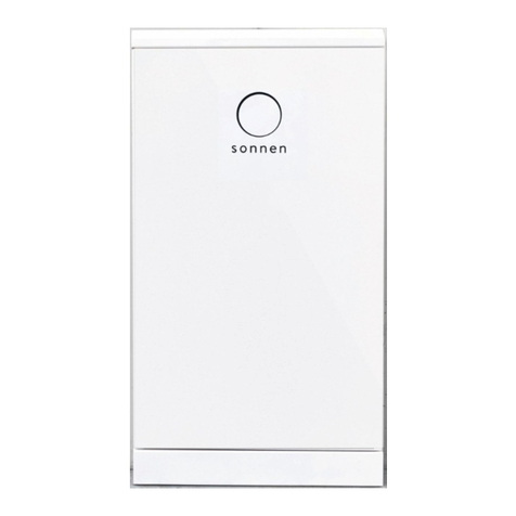
Sonnen sonnenBatterie ecoLinx 10 User manual

Installation and Operating Manual
sonnenBatterie ecoLinx


This manual refers to:
Hardware version: 2.00
Software version: 8.0.5674
Latest revision: 10/09/19
Version: 1.0
If you need help or service, contact the company that commissioned your
storage system.
Copyright
This publication, including all photographs, illustrations and software, is pro-
tected under international copyright laws, with all rights reserved. Neither
this manual, nor any of the material contained herein, may be reproduced
without written consent of the author.
© Copyright 2018
Disclaimer
The information in this document is subject to change without notice. The
manufacturer makes no representations or warranties with respect to the
contents hereof and specifically disclaims any implied warranties of mer-
chantability or fitness for any particular purpose. The manufacturer reserves
the right to revise this publication and to make changes in the content
hereof without obligation of the manufacturer to notify any person of such
revision or changes.


Contents
About this manual 1
Target audience ..............................................1
Terminology.....................................................1
Symbols used...................................................1
Safety 2
Intended use ..................................................2
Prohibited uses ..............................................2
General warnings ..........................................2
General safety instructions..........................2
Fire-related instructions...............................3
Battery module information ....................... 4
Specifications 5
Specifications.................................................5
Dimensions.....................................................9
Key components............................................9
Description of use .......................................10
Modes of operation ....................................10
Generator autostart functionality.............. 11
NEC 705.12(D)(2) calculation.................... 12
Storage and transport 13
Storing the system ...................................... 13
Transporting the system............................. 13
Installation 15
Tools needed ................................................ 15
Clearance requirements............................. 15
Inspecting the storage system .................. 16
Mounting the storage system.................... 16
Electrical connections 21
Connecting AC cables ............................... 23
Connecting a generator (optional) .......... 26
Connecting an Ethernet cable ................. 26
Generator Autostart wiring (optional) .....27
Emergency stop wiring (optional)............ 28
Connecting PV Production Meter........... 29
Installing battery modules.........................30
Commissioning 36
Commissioning checklist........................... 36
Turn on the storage system....................... 36
Commissioning assistant ............................37
Decommissioning 42
Shutting the storage system down.......... 42
Recycling and certificates......................... 42
Internet access 43
Establish connection to the Internet....... 43
Internet portal ............................................ 43
Maintenance and care 44
Function control ........................................44
Care of the storage system ......................44
Appendix 1. Nameplates 45
Appendix 2. Glossary 48
Appendix 3. Torque values 49
Appendix 4. Warranty 50

Figures
Fig. 1 Storage system dimensions .............................................9
Fig. 2 ecoLinx key components ................................................9
Fig. 3 Energy flow......................................................................10
Fig. 4 Self-consumption mode................................................10
Fig. 5 Backup mode.................................................................... 11
Fig. 6 NEC 705.12(D)(2) calculation example....................... 12
Fig. 7 Allowed tilt positions......................................................14
Fig. 8 Clearance requirements................................................ 15
Fig. 9 Mounting cleat orientation ........................................... 16
Fig. 10 Positioning the mounting bracket.............................. 17
Fig. 11 Sliding the cabinet into the mounting cleat............... 17
Fig. 12 Securing the mounting cleat ...................................... 17
Fig. 13 Unlocking the inverter cabinet ................................... 17
Fig. 14 Removing the dead front............................................. 18
Fig. 15 Connecting cabinets (left side)................................... 18
Fig. 16 Connecting cabinets (right side) ................................ 18
Fig. 17 Removing the cabinet cover........................................ 18
Fig. 18 Installing edge protectors............................................ 19
Fig. 19 Flat band grounding...................................................... 19
Fig. 20 Conduit entry location............................................... 20
Fig. 21 Removing battery cabinet access panel cover ........ 20
Fig. 22 Terminal map for ecoLinx ........................................... 22
Fig. 23 Installation using protected loads panel .................. 23
Fig. 24 Installation without protected loads panel.............. 23
Fig. 25 Stripping cable............................................................. 24
Fig. 26 Automatic transfer switch actuator ......................... 24
Fig. 27 Microgrid connections - ATS version ....................... 24
Fig. 28 Grid connections - ATS Version ................................ 25
Fig. 29 Grounding connections - ATS Version ..................... 25
Fig. 30 Generator AC connections - ATS Version............... 26
Fig. 31 Ethernet socket location - ATS version .................... 26
Fig. 32 12V signal connection ..................................................27
Fig. 33 24V signal connection.................................................27
Fig. 34 Dry Contact signal connection ................................. 28
Fig. 35 Dry Contact connection ............................................ 28
Fig. 36 Current transformer markings.................................. 29
Fig. 37 Current transformers S1 and S2................................ 29
Fig. 38 Measuring voltage on battery modules ................... 30
Fig. 39 Labeling battery modules...........................................30
Fig. 40 Defining address of battery modules ....................... 31
Fig. 41 Setting termination switch on final module.............. 31
Fig. 42 Placing battery modules ............................................. 31
Fig. 43 Inserting set screws .................................................... 32
Fig. 44 Installing horizontal battery connections................ 32
Fig. 45 Installing vertical battery connections .................... 33
Fig. 46 Installing jumper cables.............................................. 33
Fig. 47 Installing flange nuts................................................... 34
Fig. 48 Connecting BMS communication cable.................. 34
Fig. 49 Inserting safety plug ................................................... 35
Fig. 50 Switch and circuit breaker......................................... 36
Fig. 51 Identifying the storage system ...................................37
Fig. 52 Logging in to the storage system...............................37
Fig. 53 Installing system updates ............................................37
Fig. 54 Setting installation location........................................37
Fig. 55 Verifying the date and time........................................37
Fig. 56 Entering PV system information............................... 38
Fig. 57 Generator Autostart information ............................. 38
Fig. 58 Time of Use information ............................................ 38
Fig. 59 Configuring Microgrid "wake-up" times .................. 39
Fig. 60 Configuring meters .................................................... 39
Fig. 61 Inputting owner information ......................................40
Fig. 62 Providing information about installer.......................40
Fig. 63 Selecting Operating Mode ........................................40
Fig. 64 Login window............................................................... 43

Tables
Table 1 Specifications ..................................................................5
Table 2 Conduit entries and cable sizes................................. 20
Table 3 Battery module voltages............................................30
Table 4 Commissioning prerequisites.................................... 36
Table 5 Required open ports for storage system................. 43


1
About this manual
This manual describes the installation and
operation of the sonnenBatterie ecoLinx storage
system. Read this manual carefully before
beginning work and keep it near the storage
system.
Target audience
This document is intended for the following
audiences:
• Operator and end user of the storage system
• Trained and certified electrician
Some actions described in this document must
only be performed by a trained and certified
electrician. These actions are marked as follows:
Trained, electrically qualified person only!
Trained, electrically qualified persons are:
• Service partners authorized by sonnen, Inc.
• Trained, electrically qualified persons with
knowledge of all applicable regulations and
standards.
• Trained, electrically qualified persons who have
attended the training provided by sonnen.
Terminology
This document refers to the sonnenBatterie
ecoLinx as a storage system.
This manual refers to the building being
serviced by the storage system as a “house,” but
the sonnenBatterie ecoLinx can be installed in
any number of buildings or sites powered by AC
electricity.
For a full glossary of terms used in this manual,
see page 48.
Symbols used
Warnings
WARNING WORD
Warnings are indicated by this
symbol and a warning word, which
indicates the severity of the
danger. Along with the warning
are instructions for avoiding the
danger.
The following warning words are used:
• CAUTION indicates a possible hazardous
situation which could result in minor or
moderate injury.
• WARNING indicates a possible hazardous
situation which could result in death or serious
injury.
• DANGER indicates an imminent hazardous
situation which will result in death or serious
injury.
Material damage
Attention
Possible material damages are indicated in this
document with the warning word “Attention.”
Important information
Important information without danger
to injury, death, or material damage is
indicated by this symbol.
Actions
Actions to be taken are marked with a ▶. For
example:
▶Read this manual thoroughly before operating
the storage unit.
Electrical symbols
indicates protective earth (ground).
Nindicates the connection for the neutral
conductor on permanently installed equipment.

2
Safety
Intended use
Any use of the system other than the intended
use can cause serious injury, death, and damage to
the product or other assets.
• The storage system must only be used to store
electrical power.
• The storage system must only be used with the
battery modules provided.
• The storage system is intended for indoor use
only.
• The intended use includes knowledge
and application of the information in this
installation and operating manual as well as all
delivered product documentation.
Failure to comply with the warranty
conditions and the information listed in
this installation and operating manual
will void any warranty claims.
Prohibited uses
DANGER
Danger to life due to electric
shock!
Even if the utility grid fails, the
storage system will continue
delivering power. Before servicing
the storage system:
▶Turn off the storage system.
▶Turn off the main disconnect
circuit breaker.
Only authorized electrically
qualified persons can perform work
on electrical parts.
• Do not use the storage system in vehicles.
• Do not use the storage system in wet locations.
• Do not use the storage system in areas at risk
of explosion (flour dust, sawdust, etc.).
• Do not expose the storage system to direct
sunlight.
• Do not use the storage system in areas where
the ammonia content of the air exceeds 20
ppm.
• Do not use the storage system when corrosive
gases are present.
• Do not use the storage system higher than
9,842 feet (3,000 meters) above sea-level.
• Do not operate the storage system at
temperatures outside of the allowed ambient
temperature range of 41°F - 113°F (5°C - 45°C).
• Do not operate the storage system at a
humidity higher than 90%.
General warnings
Attention
Attention
Damaging of the battery modules by deep
discharge!
If the battery modules are disconnected from a
power source for longer than six months, they can
be damaged by excessive discharge.
▶If the storage system has been disconnected
from the utility grid for six months, connect
it to the utility grid and allow it to charge the
battery modules to 100%.
General safety instructions
• Do not modify the storage system.
• Do not use the storage system if it has been
damaged.
• Ensure the following regulations are observed
in the installation and connection of the
storage system and the PV system:
‒Local, regional, national, and international
regulations and guidelines
‒National Electric Code
‒ANSI/NFPA 70
‒Requirements of the servicing utility
• Ensure that all safety systems are in perfect
working order.
• Read this installation and operating manual
with care.

3
• When installing and maintaining the storage
system, wear personal protective equipment,
including safety glasses, insulated gloves, and
steel-toe shoes.
WARNING
Risk of burns!
The orange safety plugs must be
removed before working on or with
the battery modules. As long as the
plug is inserted in the battery, it is
capable of producing potentially
dangerous voltages.
When working on the storage
system:
▶Take off metallic jewelry.
▶Turn off the storage system.
▶Turn off the main disconnect.
▶Remove all orange safety plugs
from the battery modules.
▶Use insulated tools
▶Wear personal protective
equipment, including safety
glasses, insulated gloves, and
steel-toe shoes.
Fire-related instructions
CAUTION
Risk of injury from escaping
electrolyte
The battery modules in the
storage system are protected by
a number of security devices for
safe operation. Despite diligent
construction, cells inside the
battery modules can still degrade
or catch fire in the event of
mechanical damage, heat, or a fault.
Possible eects include:
• Heating of battery modules.
• Escaping electrolyte, which can
ignite and produce an explosive
flame.
• Smoke, which can irritate skin,
eyes, and throat.
Consequently:
• Do not open battery modules.
• Do not physically damage
battery modules (puncture,
deform, disassemble, etc).
• Do not modify battery modules.
• Keep battery modules away from
water (except to extinguish a fire
in the storage system).
• Do not allow battery modules to
heat up.
• Only operate battery modules in
the allowed temperature range.
• Do not short circuit battery
modules or bring them into
contact with metal.
• Do not use a battery module
after it has short-circuited.
• Do not exhaustively discharge
battery modules.
If contents escape:
• Do not enter the room.
• Avoid contact with the escaping
electrolyte.
• Contact your fire department.
Despite all of the care that goes into the design
of the storage system, fires are still possible. A fire

4
can release substances contained in the battery
modules.
In the event of a fire in the storage system or its
surroundings:
• Only fire fighters wearing proper protective
clothing (including gloves, masks, and
breathing apparatus) may enter the room with
the burning storage system.
• A fire in the storage system can be
extinguished by conventional agents.
• The use of water is advisable to cool the battery
modules and thus prevent the thermal runaway
of modules that are still intact.
Battery module information
Pertinent information on battery modules
include:
• The battery modules have a rated voltage
of 51.2 VDC and are thus in the range of
protective extra-low voltage (below 60 VDC).
• The battery modules contain no metallic
lithium.

5
Specifications
ecoLinx
model 10 12 14 16 18 20
Usable
capacity
(100% DOD)
10 kWh 12 kWh 14 kWh 16 kWh 18 kWh 20 kWh
Continuous
power output
(at 25 deg C)
7kW 8 kW 8 kW 8 kW 8kW 8kW
Dimensions
W"/H"/D"
(approx.)
26x 84x 16 26x 84x 16 26x 84x 16 26x 84x 16 26x 84 x 16 26x 84 x 16
Weight
(approx.) 622 lbs. 683 lbs. 741 lbs. 800 lbs. 850 lbs. 900 lbs.
Nominal
current 33.3A
Cell
chemistry Lithium iron phosphate (LiFePo4)
Nominal
voltage 120/240VAC
Device
protection Short circuit, overload, over temperature
Ambient
temperature 41°F - 113°F (5°C - 45°C)
Maximum
Humidity 90%, non-condensing
Applications Self-Consumption, Backup, Time of Use, Home Automation Integration
Grid
integration AC coupled
On-grid specifications
Nominal
power 7kW 8kW 8kW 8kW 8kW 8kW
Table 1 Specifications

6
ecoLinx
model 10 12 14 16 18 20
Nominal
AC current
(amps)
29.16 33.33 33.33 33.33 33.33 33.33
Grid-outage specifications
Nominal
power 7kW 8kW 8kW 8kW 8kW 8kW
Nominal
AC current
(amps)
29 33.33 33.33 33.33 33.33 33.33
Max power
100 ms — 17KVA
5s — 12KVA
30m — 9KVA
Max AC
current
(charge/
discharge)
1 ms — 100A
100 ms —70.7A
5s — 50A
30m — 37.5A
Overcurrent
protection
needed
50A
General specifications
Transfer
switch Automatic, integrated, Transfer time < 100 ms
Backup
capacity 2 kilowatt-hours per battery module, up to 20 kilowatt-hours
Certifications Certified to UL 9540 Standards. UL certified components: Battery modules –UL1973;
Inverter – UL1741; ATS – UL1008; AC Breaker – UL489
Warranty 15 years or 15,000 cycle warranty on inverter, battery modules, cabinet and
components
Inverter
efficiency 92.5% CEC weighted, 95.0% peak
Roundtrip
Eff% (Grid <>
Battery)
>= 86%
Comm. ports Serial, Ethernet

7
ecoLinx
model 10 12 14 16 18 20
Comm.
protocols Modbus
Comm.
and control
standards
Control4 and Crestron Drivers Included
EMC / EMI
protection FCC Part 15B
Total
harmonic
distortion
<5% L1-L2, <2% L-N
Cooling
Method Forced air
Noise
emission < 35dBA
AC Specifications
AC input rated
current
Pass through: 200 amps @ 240VAC
Power plant: 33.33 amps @ 240VAC
AC output
voltage 120/240 volts
AC grid voltage 120/240 volts
Nominal
frequency 60 Hz
Adjustable
frequency range +/- 0.7 Hz from nominal
Metering
capability Power meter for load and PV production; +/- 0.5 RDG (current/voltage)
Tare losses (W) 60 watts
Transient
protection IEEE C62.41 Class B
Transfer switch specifications
Current rating 200 amps switching and overcurrent protection
Voltage rating 120/240 VAC
Contacts Silver-plated

8
Transfer switch specifications
Certification Certified to UL Standards
Fault Current @
240VAC 22,000 amps
Battery specifications
Voltage 48-56 VDC
Capacity 10-20kWh (2 kWh per module)
Charge current 30A per module nominal, 70A per module max
Cell discharge 100% DoD
Overcharge
Protection Fuse protection
Sizing requirements in relation to PV inverter
ecoLinx Minimum PV size Ideal PV size
10 4 KW 8 KW
12 4.8 KW 8 KW
14 5.6 KW 8 KW
16 6.4 KW 8 KW
18 6.4 KW 8 KW
20 6.4 KW 8 KW

9
Dimensions
Fig. 1 Storage system dimensions
Key components
Fig. 2 ecoLinx key components

10
Description of use
The sonnenBatterie ecoLinx is an intelligent
storage system that monitors and controls energy
production, consumption, and storage in the house.
The sonnenBatterie ecoLinx can work with
existing or newly installed PV systems. The solar
inverter and ecoLinx storage system connect to
the same distribution panel. Solar modules do not
connect to the sonnenBatterie directly.
The storage system uses two power meters
to monitor solar power production and energy
consumption. When production is higher than
consumption, such as at midday, the ecoLinx stores
the excess energy in its lithium iron phosphate
(LiFePo4) battery modules. When consumption is
higher than production, such as in the evening, the
storage system releases the energy. In doing so,
the storage system allows you to use solar power at
night, reducing your power bill and increasing the
value of your investment in renewable energy.
The storage system also acts as a backup power
supply, meaning that if the utility grid goes out, your
appliances will be powered by the unit's stored energy.
The illustration below shows how the storage
system manages solar power (1) and power from
the utility grid (2) to maximize your energy
independence and savings on your power bill.
Fig. 3 Energy flow
Modes of operation
The sonnenBatterie ecoLinx offers three
complementary modes of operation: Self-
consumption, Backup, and Time of Use. Self-
consumption mode ensures that you are using
the power you generated even when utility grid
power is available; backup mode makes that self-
generated power available in the event of a grid
power outage.
Many utility companies are moving to a Time
of Use-based billing scheme, in which electricity
costs more during high-demand time periods. The
sonnenBatterie ecoLinx can maximize your cost
savings by using your stored battery power during
the high-cost part of the day and recharging from
solar and optionally with electricity purchased
from the grid at the lowest offered rates.
Self-consumption mode
The following images illustrate the interaction
between the storage system, the PV system, and
the utility grid in self-consumption and backup
modes:
Fig. 4 Self-consumption mode
The DC power that is generated by the PV array
(A) is converted to AC power by means of an
inverter (B). The meters (C) and (D) measure the
current electrical power in watts. The production
meter (C) measures the power production, the
B
C D
A
G
H
F
E

11
consumption meter (D) measures the power
consumption in the house. If the production is
higher than the consumption, the surplus will be
stored in the battery modules (E). The storage
system’s inverter (F) converts the AC power
to DC power while the battery modules (E) are
charging. When the production is lower than the
consumption, electric power will be released
from the battery modules to power the loads. The
storage system’s inverter (F) converts the DC
power of the battery modules (E) to AC power.
The utility’s power meter (G), measures the power
supply and the power fed back to the grid (H) by
the PV array (if applicable). The storage system
will not discharge its batteries to the grid in
normal operation.
Backup mode
Fig. 5 Backup mode
In backup mode, the storage system remains
at a constant state of charge until there is a
utility grid failure. In the event of a grid failure,
the house is powered by the energy stored in the
battery modules and generated by the PV array.
During that time, the power from the PV array
powers the house or charges the battery modules,
depending on production and consumption levels.
The storage system can also turn the PV array off
if the battery modules become fully charged.
In backup mode operation, 10-, 12-, 14-, and
16-kilowatt models of the storage unit will isolate
the microgrid from the utility grid using a 200A
automatic transfer switch. When this occurs, the
storage unit will produce grid-quality voltage and
frequency so that any grid-tied PV inverters in
the microgrid will continue to operate. The PV
array will first power the loads on the AC panel,
with any excess energy charging the batteries
in the storage unit. If there is insufficient PV to
cover the loads, the storage unit will discharge its
batteries to meet demand.
To prevent battery overcharging while in backup
mode, the storage unit will perform a frequency
shift to 60.9 Hz when its state of charge reaches
95 percent. Because the PV inverter is still subject
to UL1741 conditions, it will think that the "grid"
is out of spec for the frequency threshold (59.3 -
60.5 Hz) and will disconnect from the microgrid.
When the storage unit's state of charge drops to
89 percent, it will reduce the frequency to 60
Hz. The PV inverter will see that the frequency
is within the UL1741 range and start its 5-minute
countdown before it attempts to reconnect to the
microgrid and produce power.
If the loads are small and the PV production is
high, then this behavior could occur multiple times
per day.
Attention
Altering a PV inverter's frequency could
damage the PV inverter, the storage system, and
the installation site.
It is the installer's responsibility to ensure
the PV inverter is suitable for use with the
sonnenBatterie storage system.
Generator autostart functionality
The sonnenBatterie ecoLinx can provide a start
signal for a generator to provide power in the
event that the storage system has reached a low
state of charge, the grid is unavailable, and the
PV system is not producing power. When these
criteria are met, the storage system will start the
generator and keep it running until the battery
modules have reached a pre-configured state
of charge, the grid becomes available, or the PV
system begins producing power.

12
NEC 705.12(D)(2) calculation
Because residential energy storage is a new
and emerging technology, some installers and
inspectors are unfamiliar with how to take the
sonnenBatterie ecoLinx storage system into
account when sizing distribution panels in regards
to NEC 705.12(D)(2), the 120% rule. Because
the storage system has dedicated grid and
microgrid ports, only load centers located on the
microgrid side need to take the output of the
sonnenBatterie ecoLinx into consideration.
The storage system only discharges energy
when loads are present “downstream”; that is,
on the protected load panel. This is in contrast
to a PV system, which supplies energy whenever
grid voltage is present. Because of this, the main
service panel should be sized for only grid and PV,
if applicable. The protected load panel, however,
needs to take the grid supply overcurrent
protection device, PV, and the storage system into
account for proper rating.
The storage system incorporates an internal
power meter to measure loads. This meter uses
current transformers on the microgrid side of
the storage system to determine when loads
are present and how much energy to discharge.
Because of this design, the storage system will not
discharge more energy than necessary to power
loads on the microgrid. The main distribution
panel, located on the grid side of the storage
system, need not take the sonnenBatterie ecoLinx
into consideration because the storage system will
not discharge to upstream loads.
The overcurrent protection device used to
supply the sonnenBatterie ecoLinx can be up to
200 amps, based on the storage system’s internal
ATS and wiring, as the sonnenBatterie ecoLinx will
act as a pass-through for the grid power to serve
the load distribution panel. PV in excess of loads
also has a path to the grid from the microgrid load
distribution panel. See the example illustration
below.
ecoLinx output
sonnen ecoLinx max output
Fig. 6 NEC 705.12(D)(2) calculation example
This manual suits for next models
5
Table of contents
Other Sonnen Storage manuals

Sonnen
Sonnen sonnenBatterie hybrid 9.53 User manual

Sonnen
Sonnen sonnenBatterie eco 8.0 User manual

Sonnen
Sonnen sonnenBatterie eco 9.43 User manual
Sonnen
Sonnen sonnenBatterie hybrid 9.53/5 User manual

Sonnen
Sonnen sonnenEvo User manual
Sonnen
Sonnen sonnenBatterie eco 8.0/2,5 User manual
Sonnen
Sonnen eco Gen 3.1 Series Guide
Sonnen
Sonnen sonnenBatterie 10 User manual
Sonnen
Sonnen sonnenBatterie hybrid 8.1/6 User manual
Sonnen
Sonnen eco Gen3.1 User manual
