BIOS WEATHER 315BC User manual
Project Type
Instructions
Date: February 20 2020
Customer: Thermor Ltd
Job Number: TH1738
Item Number: 315BC
Designer: Alex Vranjesevic
PO: 24568-00
Revision: A
Artwork is not to be amended or scaled. If any changes
are required please send through Thermor oce with
instructions, and we will amend here and resend artwork
through. PLEASE RETURN WITH SIGNATURE
Contact: Graphic’s Department
Colour Breakdown
Reason For Project:
New Item:
New Branding:
Design Update:
N/A: X
UPC (For Reference Only)
Indoor/Outdoor
Wireless Thermometer
Project Type
Instructions
Date: February 20 2020
Customer: Thermor Ltd
Job Number: TH1738
Item Number: 315BC
Designer: Alex Vranjesevic
PO: 24568-00
Revision: A
Artwork is not to be amended or scaled. If any changes
are required please send through Thermor oce with
instructions, and we will amend here and resend artwork
through. PLEASE RETURN WITH SIGNATURE
Contact: Graphic’s Department
Colour Breakdown
Reason For Project:
New Item:
New Branding:
Design Update:
N/A: X
UPC (For Reference Only)
1.
2.
C.
A.
B.
Monitor / Moniteur :
Monitor / Moniteur :
Sensor / Capteur :
Sensor / Capteur :
E.
D. 3.
4.
5.
Project Type
Instructions
Date: February 20 2020
Customer: Thermor Ltd
Job Number: TH1738
Item Number: 315BC
Designer: Alex Vranjesevic
PO: 24568-00
Revision: A
Artwork is not to be amended or scaled. If any changes
are required please send through Thermor oce with
instructions, and we will amend here and resend artwork
through. PLEASE RETURN WITH SIGNATURE
Contact: Graphic’s Department
Colour Breakdown
Reason For Project:
New Item:
New Branding:
Design Update:
N/A: X
UPC (For Reference Only)
Indoor/Outdoor
Indoor/Outdoor
Wireless Thermometer
Wireless Thermometer
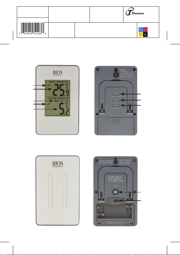
Monitor
Monitor
A. Indoor Temperature Trend
A. Indoor Temperature Trend
B. Indoor Temperature
B. Indoor Temperature
C. Channel
C. Channel
D. Outdoor Temperature Trend
D. Outdoor Temperature Trend
E. Outdoor Temperature
E. Outdoor Temperature
1. Max/Min Button
1. Max/Min Button
2. CH Button
2. CH Button
3. °C/°F Button
3. °C/°F Button
Sensor:
Sensor:
4. TX Button
4. TX Button
5. Channel Switch (Under Battery Cover)
5. Channel Switch (Under Battery Cover)
Care of the Device
Care of the Device
• Avoid exposing units to extreme temperatures or severe shock.
• Avoid contact with any corrosive materials such as perfume, alcohol or
cleaning agents.
•
Do not
Do not subject the units to excessive force, shock, dust, temperature or
humidity. Any of these conditions may shorten the life of the units.
•
Do not
Do not tamper with any of the internal components of these units. This
will invalidate the warranty and may cause damage.
Correct Usage of Batteries
Correct Usage of Batteries
•
Do not
Do not mix standard and rechargeable batteries.
•
Do not
Do not mix new and old batteries.
• When the low battery symbol appears on the display replace all
batteries with new ones.
Setup Procedure
Setup Procedure
1. Insertbatteriesintothemonitorrst.
2. Using a screwdriver (not included) remove the screws on the back of the
sensor to open the battery compartment.
3. Place the monitor as close as possible next to the remote sensor. Before
inserting the batteries into the sensor ensure the correct channel is
selected, then insert the batteries into the remote sensor.
4. The remote sensor will send a signal to the monitor. Once the signal is
received, the dashes (--.-°F) on the monitor will change to the current
outdoor temperature.

Project Type
Instructions
Date: February 20 2020
Customer: Thermor Ltd
Job Number: TH1738
Item Number: 315BC
Designer: Alex Vranjesevic
PO: 24568-00
Revision: A
Artwork is not to be amended or scaled. If any changes
are required please send through Thermor oce with
instructions, and we will amend here and resend artwork
through. PLEASE RETURN WITH SIGNATURE
Contact: Graphic’s Department
Colour Breakdown
Reason For Project:
New Item:
New Branding:
Design Update:
N/A: X
UPC (For Reference Only)
NOTE:
NOTE: If after 5 minutes the screen does not change to show the
outdoor temperature, remove all batteries for both units and
insert again, starting with the monitor.
5. Positionthemonitorandremotesensorwithineectivetransmission
range, which in usual circumstances is 25 meters (82 feet). The range
isaectedbythebuildingmaterialsandwherethemonitorandremote
sensor are positioned; try various locations for the best results.
NOTE:
NOTE: The remote sensor should be placed outdoors in a shaded area for
accurate readings.
Troubleshooting
Troubleshooting
If the outdoor temperature cannot be received, check:
1. The distance between the monitor or remote sensor should be at least
1.2 meters (4 feet) away from any interfering sources such as computer
monitors or TV sets.
2. Avoid placing the monitor onto or in the immediate proximity of metal
window frames.
3. Using other electrical products such as headphones or speakers
operating on the same frequency (433MHz) may prevent correct signal
transmission and reception.
4. Neighbors using electrical devices operating on the 433MHz signal
frequency can also cause interference.
5. Signals from other household devices, such as door bells and home
security systems, may temporarily interfere with the units and cause
reception failure. The transmission and reception of temperature reading
will resume once the interference has stopped.
The maximum transmission range is 25 meters (82 feet) from the remote
sensor to the monitor (in open space). However, this depends on the
surrounding environment and interference levels. The temperature signal
travels in a straight line from the remote sensor to the monitor. The signal
will not curve around an object. If no reception is possible, despite the
observation of these factors, all units will have to be reset.
DisplayingDierentChannels
DisplayingDierentChannels
If you have registered more than one remote sensor, press the
CH
CH button
on the monitor to select the outdoor sensor channel you want to display
permanently. To display each channel for 5 to 10 seconds on the monitor,

Project Type
Instructions
Date: February 20 2020
Customer: Thermor Ltd
Job Number: TH1738
Item Number: 315BC
Designer: Alex Vranjesevic
PO: 24568-00
Revision: A
Artwork is not to be amended or scaled. If any changes
are required please send through Thermor oce with
instructions, and we will amend here and resend artwork
through. PLEASE RETURN WITH SIGNATURE
Contact: Graphic’s Department
Colour Breakdown
Reason For Project:
New Item:
New Branding:
Design Update:
N/A: X
UPC (For Reference Only)
press the
CH
CH button until is displayed on the LCD.
The monitor will auto-scroll through all the channels.
Press and hold the
CH
CH button if the outdoor temperature needs to be reset.
The outdoor temperature of that particular channel will reset and display
dashes (--.-°C). Press the
TX
TX button on the back of the sensor to force
the sensor to send a transmission to the monitor, and then the current
temperature should once again be displayed on the monitor.
Installing the Monitor
Installing the Monitor
Themonitorcanbeplacedonanyatsurfaceor
mounted on a wall.
IMPORTANT:
IMPORTANT:
Do not
Do not place the monitor in direct
sunlight or where exposed to any other sources
of heat or air conditioning to ensure accurate
temperature readings.
Installing the Remote Sensor
Installing the Remote Sensor
To prevent temperature interference, place the
remote sensor outside away from direct sunlight,
and rain. The remote sensor is designed to be splash
proof; never immerse into water or expose to heavy
rain.
Maximum and Minimum Memory
Maximum and Minimum Memory
1. Press the
MAX/MIN
MAX/MIN button once to display the minimum readings. Press
the
MAX/MIN
MAX/MIN button again to display the maximum readings.
2. To clear the memory, press and hold the
MAX/MIN
MAX/MIN button when the max
or min readings are displayed. This will reset the memory to the current
temperature readings being displayed on the monitor.
°C/°F Switchable
°C/°F Switchable
The default measurement for temperature is °F, press the
°C/°F
°C/°F button to
toggle between °C and °F.

Project Type
Instructions
Date: February 20 2020
Customer: Thermor Ltd
Job Number: TH1738
Item Number: 315BC
Designer: Alex Vranjesevic
PO: 24568-00
Revision: A
Artwork is not to be amended or scaled. If any changes
are required please send through Thermor oce with
instructions, and we will amend here and resend artwork
through. PLEASE RETURN WITH SIGNATURE
Contact: Graphic’s Department
Colour Breakdown
Reason For Project:
New Item:
New Branding:
Design Update:
N/A: X
UPC (For Reference Only)
Specications
Specications
Temperature Measuring Range
Temperature Measuring Range
Monitor 0°C to 50°C (32°F to 122°F)
Outdoor Sensor -35°C to 70°C (-31°F to 158°F)
Temperature Checking Interval
Temperature Checking Interval
Monitor 35 seconds
Outdoor Sensor 35 seconds
Power Source
Power Source
Monitor 2 x AAA batteries, 1.5V
Outdoor Sensor 2 x AAA batteries, 1.5V
(it is recommended to use Lithium
batteries during the cold months)
Industry Canada/FCC Statement
Industry Canada/FCC Statement
Operation is subject to the following two conditions: (1) this device may
not cause interference, and (2) this device must accept any interference,
including interference that may cause undesired operation of the device.
WARNING:
WARNING: Changes or modications to this unit not expressly approved
by the party responsible for compliance could void the user’s authority to
operate the equipment.
NOTE:
NOTE: This equipment has been tested and found to comply with the limits
for a Class B digital device, pursuant to Part 15 of the FCC Rules. These limits
are designed to provide reasonable protection against harmful interference
in a residential installation. This equipment generates, uses and can radiate
radio frequency energy and, if not installed and used in accordance with the
instructions, may cause harmful interference to radio communications.
However, there is no guarantee that interference will not occur in a particular
installation. If this equipment does cause harmful interference to radio or
Project Type
Instructions
Date: February 20 2020
Customer: Thermor Ltd
Job Number: TH1738
Item Number: 315BC
Designer: Alex Vranjesevic
PO: 24568-00
Revision: A
Artwork is not to be amended or scaled. If any changes
are required please send through Thermor oce with
instructions, and we will amend here and resend artwork
through. PLEASE RETURN WITH SIGNATURE
Contact: Graphic’s Department
Colour Breakdown
Reason For Project:
New Item:
New Branding:
Design Update:
N/A: X
UPC (For Reference Only)
televisionreception,whichcanbedeterminedbyturningtheequipmento
and on, the user is encouraged to try to correct the interference by one or
more of the following measures:
• Reorient or relocate the receiving antenna.
• Increase the separation between the equipment and receiver.
•Connect theequipment intoan outleton acircuit dierent fromthat to
which the receiver is connected.
• Consult the dealer or an experienced radio/TV technician for help.
Two Year Warranty
Two Year Warranty
The BIOS Weather Indoor/Outdoor Wireless Thermometer has a two year
warranty to be free of manufacturing defects in materials and workmanship
under normal applications for two year of the original owner. If this product
becomes inoperable due to defect and requires repair, return the product
with all component pieces and proof of purchase to the address listed
below. This warranty does not cover any shipping/transport costs. This
warranty does not apply if the product is subject to misuse, neglect, rough
handling or damage.
Ship the unit prepaid and insured (at owner’s option) to:
Thermor Ltd.
Attn: Repair Department
16975 Leslie Street
Newmarket, ON L3Y 9A1
www.biosmedical.com
Email: [email protected]
Table of contents
Other BIOS WEATHER Thermometer manuals


