Delta OHM HD2205.2 User manual

Our instruments' quality level is the results of the product continuous development. This
can bring about differences between the information written in this manual and the instru-
ment that you have purchased. We cannot entirely exclude errors in the manual, for which
we apologize.
The data, figures and descriptions contained in this manual cannot be legally asserted. We
reserve the right to make changes and corrections without prior notice.
REV. 1.0
18 Oct. 2006
HD2205.2
HD2206.2
HD2256.2

- -
2
HD2205.2 Dual pH - Temperature
HD2206.2 Conductivity - Temperature
HD2256.2 pH - Conductivity - Temperature
1. LCD Display
2. CONTRAST+ key, allows to increase the display contrast.
3. CONTRAST- key, allows to decrease the display contrast.
4. Function keys F1, …, F5.
5. ID key, allows to set the sample identifier number.
6. LOG key: starts and ends the saving of the data in the internal memory.
7. key: in the menu, increases the current value.
8. ENTER key: in the menu, confirms the current selection.
9. key: in the menu, moves the cursor leftwards.
10. ESC key: in the menu, cancels the operation in progress without making changes.
11. key: in the menu, decreases the current value.
12. SETUP key: allows access to the menu.
13. MEM key: stores the currently displayed screen.
14. key: in the menu, moves the cursor rightwards.
15. CAL key starts the pH electrode, conductivity probe calibration procedure.
16. HELP key: shows a description of the instrument main functions on the display.
17. SHIFT/FNC key: enables the secondary functions linked to the F1, …, F5 keys.
18. PRINT key: prints the data on the current screen. It uses the serial communication port
RS232C or the USB port.
19. ON-OFF key: turns the instrument on and off.

- -
3
HD2205.2 connectors: Dual pH - Temperature
20. Power supply input 12Vdc for the ∅5.5mm - 2.1mm connector. Positive at centre.
21. RS232C serial port, sub D 9-pole male connector.
22. 8-pole DIN45326 connector, input for Pt100 temperature probes with SICRAM module, 4 wire
direct Pt100 probes, 2 wire direct Pt1000 probes 5.
23. 8-pole DIN45326 connector, for the combined pH/mV/temperature electrode with SICRAM
module - channel 1 3.
24. Socket for ∅4mm standard plug for the reference electrode pH/ISE - channel 1.
25. BNC connector for the pH/mV electrode - channel 1 1.
26. Auxiliary power supply output 12Vdc/200mA max. for the stirrer - ∅5.5mm - 2.1mm connec-
tor.
27. USB 2.0 connector - type B.
28. 8-pole DIN45326 connector, for the combined pH/mV/temperature electrode with SICRAM
module - channel 2 4.
29. Socket for ∅4mm standard plug for the reference electrode pH/ISE - channel 2.
30. BNC connector for the pH/mV electrode - channel 2 2.

- -
4
HD2206.2 connectors: Conductivity - Temperature
20. Power supply input 12Vdc for the ∅5.5mm - 2.1mm connector. Positive at centre.
21. RS232C serial port, sub D 9-pole male connector.
22. 8-pole DIN45326 connector, input for combined 4-ring or 2-ring conductivity/temperature
probes complete with SICRAM module i.
23. 8-pole DIN45326 connector, input for Pt100 temperature probes with SICRAM module, 4 wire
direct Pt100 probes, 2 wire direct Pt1000 probes 5.
24. Not used.
25. Auxiliary power supply output 12Vdc/200mA max. for the stirrer - ∅5.5mm - 2.1mm connec-
tor.
26. USB 2.0 connector - type B.
27. 8-pole DIN45326 connector, input for combined 4-ring or 2-ring conductivity/temperature
probes without SICRAM module j.
28. Not used.

- -
5
HD2256.2 connectors: pH - Conductivity - Temperature
20. Power supply input 12Vdc for the ∅5.5mm - 2.1mm connector. Positive at centre.
21. RS232C serial port, sub D 9-pole male connector.
22. 8-pole DIN45326 connector, input for combined 4-ring or 2-ring conductivity/temperature
probes complete with SICRAM module i.
23. 8-pole DIN45326 connector, input for Pt100 temperature probes with SICRAM module, 4 wire
direct Pt100 probes, 2 wire direct Pt1000 probes 5.
24. 8-pole DIN45326 connector, for the combined pH/mV/temperature electrode with SICRAM
module - channel 1 3.
25. Socket for ∅4mm standard plug for the reference electrode pH/ISE.
26. BNC connector for the pH/mV electrode 1.
27. Auxiliary power supply output 12Vdc/200mA for the stirrer - ∅5.5mm - 2.1mm connector.
28. USB 2.0 connector - type B.
29. 8-pole DIN45326 connector, input for combined 4-ring or 2-ring conductivity/temperature
probes without SICRAM module j.
30. Not used.

- -
6
INTRODUCTION
The HD2205.2, HD2206.2 and HD2256.2 are laboratory instruments for electrochemical measure-
ments: pH, conductivity and temperature. They are fitted with a large backlit LCD display.
The HD2205.2 is fitted with two BNC inputs for pH, mV, redox potential (ORP) measurement us-
ing pH, redox electrodes or separate reference electrodes, and two inputs for pH/temperature probes
complete with SICRAM module.
The HD2206.2 measures conductivity, liquid resistivity, total dissolved solids (TDS) and salinity
using combined 4-ring and 2-ring conductivity/temperature probes. The conductivity probes can
have a direct input or a SICRAM module; the inputs are separate.
The HD2256.2 measures pH, mV, redox potential (ORP) using pH, redox electrodes or separate
reference electrodes; conductivity, liquid resistivity, total dissolved solids (TDS) and salinity us-
ing combined 4-ring and 2-ring conductivity/temperature probes. The inputs are separate. One for
the 4-ring and 2-ring direct probes, the other for the probes fitted with SICRAM module.
The instruments have an input for the immersion, penetration or contact temperature probes. The
sensor can be a Pt100 or Pt1000.
•The pH electrode calibration can be carried out on one or five points, and the calibration se-
quence can be chosen from a list of 13 buffers. The temperature compensation can be auto-
matic or manual.
•The calibration of the conductivity probe can be automatic, by recognition of standard solu-
tions: 147μS/cm, 1413μS/cm, 12880μS/cm, 111800μS/cm or manual with different solutions.
•The pH, conductivity and temperature probes are fitted with a SICRAM module, with the fac-
tory calibration settings already being memorized inside.
The devices of the HD22… series are dataloggers. They memorize up to 2,000 samples of:
•pH or mV and temperature the HD2205.2,
•conductivity or resistivity or total dissolved solids or salinity and temperature the HD2206.2,
•pH or mV, conductivity or resistivity or total dissolved solids or salinity and temperature the
HD2256.2.
The data can be transferred from the instrument connected to a PC via the RS232C serial port or the
USB 2.0 port. The recording parameters can be configured using the menu.
The RS232C serial port can be used for direct printing of the data using a 24 column printer
(S’print-BT).
The instruments equipped with the Bluetooth HD22BT option, can send the data to a PC fitted with
the USB/Bluetooth HD USB.KL1 converter, to a printer with a Bluetooth S’print-BT interface, or to
a PC fitted with a Bluetooth input, without the need of any connection.
The DeltaLog11 dedicated software allows management and configuration of the instrument, and
data processing on the PC.
The instruments have IP66 protection degree.
If not otherwise specified, this manual's descriptions are intended to be applicable to all mod-
els.

- -
7
DISPLAY DESCRIPTION
HD2205.2
HD2206.2
HD2256.2
The above appears when you turn the instrument on.
The display is backlit. The contrast level is adjusted using CONTRAST+ and CONTRAST-.
The display has three lines described below:
First line
HD2205.2
It indicates, from left to right:
1. The pH or mV value measured by the electrode connected to the BNC input c,or by the
SICRAM pH probe connected to the input e, (pH#1 o mV#1),
2. The pH or mV value measured by the electrode connected to the BNC input d,or by the
SICRAM pH probe connected to the input f,(pH#2 o mV#2),

- -
8
3. The temperature value used to compensate the pH measurements (for a detailed description, see
the chapter dedicated to temperature on page 36).
HD2206.2
It indicates, from left to right:
1. The conductivity, resistivity, TDS, NaCl concentration measured by the conductivity probe, with
SICRAM module, connected to the input i,or by the direct probe, without SICRAM mod-
ule, connected to the input j,
2. The temperature value used to compensate the conductivity measurements (for a detailed de-
scription, see the chapter dedicated to temperature on page 36).
HD2256.2
It indicates, from left to right:
1. The pH or mV value measured by the electrode connected to the BNC input c,or by the
SICRAM pH/temperature probe connected to the input e,
2. The conductivity, resistivity, TDS, NaCl concentration measured by the conductivity probe, with
SICRAM module, connected to the input i,or by the direct probe, without SICRAM mod-
ule, connected to the input j,
3. The temperature value used to compensate the pH and/or conductivity measurements (for a de-
tailed description, see the chapter dedicated to temperature on page 36).

- -
9
Central line
HD2205.2
HD2206.2
HD2256.2
It indicates, from left to right:
4. In models HD2205.2 and HD2256.2: The symbol indicates the quality of the pH electrode con-
nected to the inputs cor e, or the CAL blinking message if the probe connected to the pH
input is not calibrated. The symbol shows an electrode that gets “empty” as its efficiency de-
creases.
In the HD2206.2 instrument, the cell constant value of the conductivity probe connected to in-
puts ior j. It has up to 4 different calibration points and nominal cell constant corrections.
The displayed value is referred to the calibration point at 1413μS/cm.
5. In the HD2205.2 instrument, the symbol indicates the quality of the pH electrode connected to
the inputs dor f, or the CAL blinking message if the probe connected to the pH input is not
calibrated.
In the HD2206.2 instrument, the temperature coefficient αT
In the HD2256.2 instrument, the cell constant value of the conductivity probe connected to in-
puts ior j. It has up to 4 different calibration points and nominal cell constant corrections.
The displayed value is referred to the calibration point at 1413μS/cm.
6. The EPT (End PoinT) symbol indicates the display mode. The mode selection is done using the
ENDPNT function key (SHIFT/FNC key >> F4 key). When EPT is blinking, the measurement
is updated on the display; when it is fixed, the measurement is “frozen”. For a new measurement,
press F3 = MEAS.
EPT = DIR: The instrument operates in continuous view mode. In this mode the displayed
measurement is updated every second (standard mode).
EPT = MAN: The displayed measurement is continuously updated until F3 = MEAS is
pressed. During the measurement update, the EPT-MAN symbol is blinking. For a new
measurement, press MEAS.
EPT = TIME: The measurement is frozen after a set time of 8 seconds. For a new measure-
ment, press MEAS.
EPT = AUTO: The instrument performs the measurement, and when it stabilizes the EPT-
AUTO symbol stops blinking. For a new measurement, press MEAS.

- -
10
In the following figure you can see an example of the measurement process with the EPT
AUTO function enabled. After setting the EPT = AUTO function using the F4 key, the elec-
trode is immersed into a liquid. To perform the measurement, press MEAS. the EPT symbol
blinks to indicate that the measurement is in the stabilization phase. In the stretch indicated by
1, the measurement remains within a stability range for 8 seconds: at the end of this interval
(point 2), the instrument freezes the measurement, presenting the final stable value. The EPT
AUTO symbol stops blinking.
For a new measurement, press MEAS.
2 digit
10s
t
p
H
pH
1
The reference stability range has a span of 2 digits.
When recording is started (Logging), the ENDPNT function switches automatically to DIR.
7. ATC or MTC indicate the temperature compensation type being used.
ATC means automatic compensation: If the temperature probe is present, compensation is car-
ried out according to this probe, or according to the temperature detected by a combined
probe, if present. In this case, you cannot modify the manually input temperature value.
MTC means manual compensation: there are no temperature sensors; the temperature used for
compensation is typed using the keyboard. Press the “F5 - °C/°F” key once to modify its
value: the message eblinks. Use the and arrows to set the desired value and con-
firm with ENTER. The display stops blinking, and the temperature displayed is used for
compensation.
If the temperature probe is not present, in order to change the unit of measurement between °C
and °F, it is necessary to press the F5 = °C/°F key twice.

- -
11
Bottom line
The following is reported in the bottom line:
8. Identifier of the sample being measured: The automatically increased progressive number
associated with the PRINT and MEM functions. The identifier is indicated in the printout and
in the recorded samples together with the date, time and measured values.
To set the number associated to the first sample, press ID, then use the and arrows to se-
lect the desired number: Confirm by pressing ENTER. This parameter can be modified only by
the administrator (see page 21).
If the EPT option is set to DIR (see point 6 in this chapter), each time the PRINT or MEM key
is pressed, the identification ID is increased by 1.
If the EPT option is set to Auto, Man or Time, pressing PRINT only causes the print to occur
when the measurement has stabilized (EPT symbol still); until the measurement is frozen, it is
possible to repeat the print at will, but the sample identifier number is not increased. This is
useful when more labels concerning a single measurement must be printed with the same iden-
tification code, without increasing the code each time.
9. MEM reports the number of samples contained in the instrument’s memory.
10. Current date expressed as year/month/day.
11. Current time expressed as hours/minutes/seconds.
- -
12
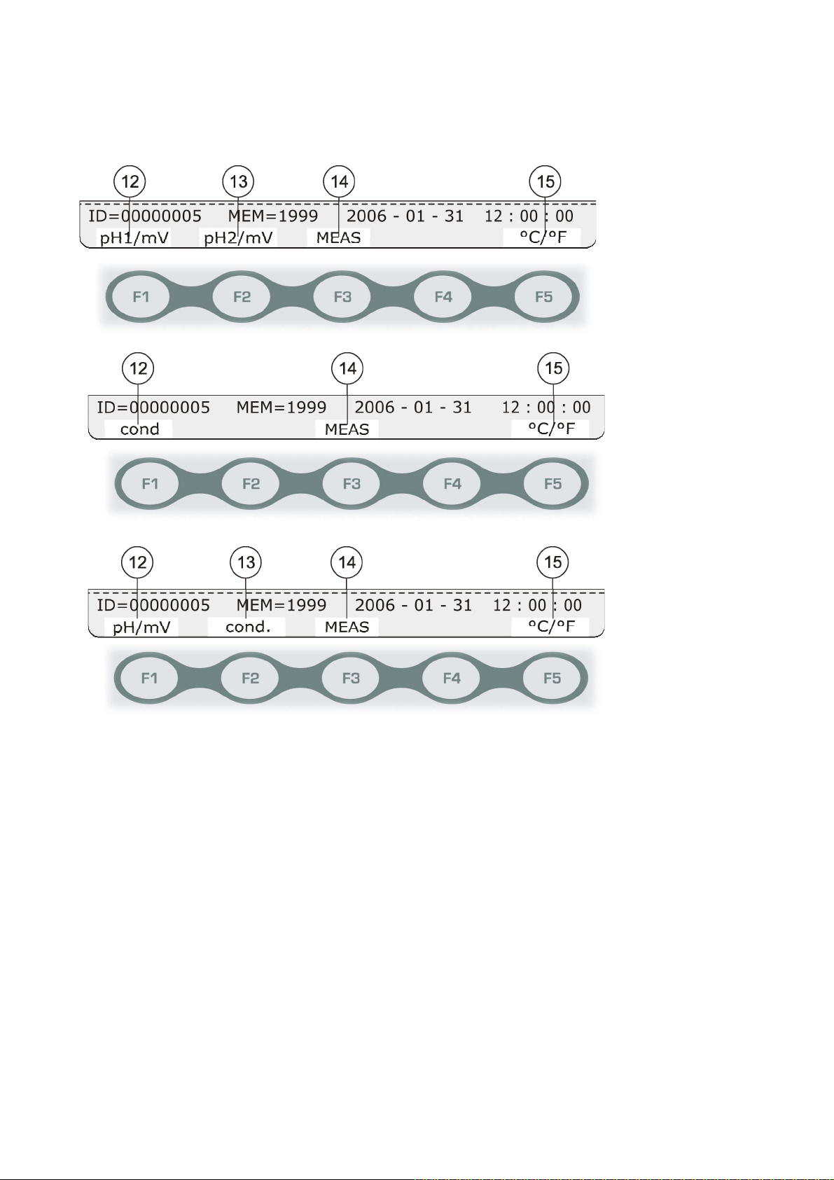
Function keys
The bottom line is associated to the F1, …, F5 function keys. When you turn the instrument on, the
following messages appear.
HD2205.2
HD2206.2
HD2256.2
12. F1 - Models HD2205.2 and HD2256.2 - If you press it repeatedly, it changes the unit of meas-
urement of the electrode connected to the BNC input cor of the SICRAM pH probe con-
nected to the input 3between pH, mV, or no indication.
F1 - Model HD2206.2 - If you press it repeatedly, it changes the measurement performed on
the probe connected to the input i(SICRAM probe) or input j(direct probe without
SICRAM), between conductivity, resistivity, TDS, NaCl concentration, or no indication.
13. F2 - Model HD2205.2 - If you press it repeatedly, it changes the unit of measurement of the
electrode connected to the BNC input dor of the SICRAM pH probe connected to the input
4between pH, mV, or no indication.
F2 - Model HD2206.2 – Function not enabled.
F2 - Model HD2256.2 - If you press it repeatedly, it changes the measurement performed on
the probe connected to the input i(SICRAM probe) or input j(direct probe without
SICRAM), between conductivity, resistivity, TDS, NaCl concentration, or no indication.
14. F3 Allows to carry out a new measurement, when the EPT = AUTO, MAN or TIME modes are
selected.

- -
13
15. F5 = °C/°F: If the temperature sensor is present, the key changes the unit of measurement be-
tween °C or °F. If no temperature or combined temperature probes are present, the key allows
manual input of the temperature value used for compensation and of the unit of measurement
(°C or °F). See also point 7.
By pressing the SHIFT/FNC key, you can access the secondary functions linked to the F1, …, F5
function keys.
16. F1 = M-STOR - Stores the current information. It performs the same function as the MEM
key.
When EPT is different from DIR (see point 6), the logging is disabled until the measurement is
stable: M-STOR is displayed only when the measurement is stable.
17. F3 = MEAS - Allows to perform or repeat a new measurement, when the EPT = AUTO, MAN
or TIME modes are selected (see point 6).
18. F4 = ENDPNT - Selects the displayed measurement update mode (see point 6)
19. F5 = M-VIEW - Allows to display the stored data or to clear the memory. See the details on
page 49.

- -
14
KEYBOARD DESCRIPTION
Each key specific function is described in detail below.
ON-OFF key
The instrument is turned on and off using the ON/OFF key. Press this key for at least two sec-
onds. The turning on starts a self test including the detection of the probes connected to the inputs.
As the probes’ identification and calibration data are captured upon turning the instrument
on, it is necessary to connect them when the instrument is off. If a probe is connected and the
instrument is on, it is necessary to turn it off and on.
Finally, the instrument is set for normal measurement.
Once turned off, wait few seconds before turning it on to allow completion of the shut down rou-
tine.
PRINT key
It sends the displayed data to the serial RS232C or USB output.
If EPT = DIR, the identification ID is increased by 1 (see page 11).
Before starting the communication via the RS232C serial port, set the baud rate. To do so, select
“System Parameters >> RS232 Speed (Baud Rate)” and select the maximum value equal to 115200
baud by using the arrows and . Confirm by pressing ENTER.
The DeltaLog11 software for PC will automatically set the baud rate value during connection by
reading it on the instrument. If you are using a different program than DeltaLog11, be sure the
baud rate is the same for both the instrument and the PC: the communication will only work
in this way.
If the instrument is connected directly to a serial printer, set the recommended baud rate for the
printer. See the details on page 50.
CONTRAST+ key:
This key allows to increase the display contrast.
CONTRAST- key:
This key allows to decrease the display contrast.

- -
15
…
Function keys F1, …, F5
The function of the F1, …, F5 keys is described by the message near each key in the bottom line of
the display. A complete description of these keys is reported on page 12.
SHIFT/FNC key
The F1…F5 keys have two functions: the main and the secondary functions. By pressing the
SHIFT/FNC key, you can toggle between the two functions.
LOG key
It starts and stops the logging of a data block to be saved in the instrument's internal memory. The
data logging frequency is set in the “System Parameters >> Logging Options >> Select Log Inter-
val”menu. The data logged between a start and subsequent stop represent a data block.
When the logging function is on, the “NOW LOGGING!” indication is displayed. Upon each
recording, the identification ID and the MEM counter are increased by 1 (see page 11).
To end the logging, press LOG.
For the details see the chapter dedicated to recording on page 49.
ID key
This key allows to input the value of the first sample ID associated with the PRINT function. Use
the and arrows to select the value to be modified, and set the desired value using the and
arrows. Modify the other values in the same way. At the end, confirm with ENTER. For the de-
tails, see the description on page 11.
This parameter can be modified only by the administrator (see page 21).
HELP key
It displays a short help on the instrument’s main functions. Press ESC to go back to standard meas-
urement. Use ENTER to browse the HELP items.

- -
16
CAL key
Starts the pH electrodes, conductivity probe calibration procedure (see the chapter dedicated to
calibration on page 25).
ENTER key
In the menu, the ENTER key confirms the current parameter.
ESC key
In the menu, the key clears or cancels the active function.
MEM key
It stores the displayed data.
The data refer to the following measurements:
pH, mV and temperature for the HD2205.2;
conductivity, resistivity, total dissolved solids, NaCl and temperature for the HD2206.2,
pH, mV, conductivity, resistivity, total dissolved solids, NaCl and temperature for the
HD2256.2,
The units of measurements are those selected on logging using the F1 and F2 function keys. For the
details see the chapter dedicated to recording on page 49.
SETUP key
Using this button the instrument’s menu can be accessed. See a detailed description on page 17.

- -
17
MENU DESCRIPTION
The SETUP key is used to access the menu main screen. To select one item, use the arrow keys (
and ).
Press ENTER to access the selected item. Use the and arrows to browse the submenus and
modify the single parameters. Press ENTER to confirm the value of the selected parameter, press
ESC to cancel the operation: In both cases, you return to the initial menu.
Press ESC to return to the main menu from a submenu, and to exit the main menu and return to
measurement mode.
Note: Some parameters can be changed only by an user registered as “Administrator” (see the de-
tails on page 21).
Language selection
The menu items are in 4 languages: Italian, English, French and Spanish. To select the language,
press SETUP, use the and arrows to select “Languages / Users / Passwords” >> “User Reg-
istration” and select the language using the SETUP key. Press ESC to confirm and return to meas-
urement mode.
The menu items are listed in this order:
1. “INFORMATION / STATUS / HELP”
1.1. “Instrument Info” shows some information for the instrument: model, types of meas-
urement, firmware version, serial number and calibration date.
1.2. “Instrument Status” reports the last enabled user, the current type and status of commu-
nication interface, the temperature compensation mode and the temperature sensor used
for compensation.
1.3. “Short Reference Manual”. It is a short help showing the instrument main functions.
2. “LANGUAGE / USERS / PASSWORDS”
2.1. “User Registration, current…” selects the language among Italian, English, French or
Spanish and/or the current user type. See the details on page 21.
2.2. “Create / Edit User Password” allows to create and/or edit the password associated to
each registered user: Administrator, User_1, User_2 and User_3. See the details on page
21.
2.3. “User Exit Mode”: When you turn the instrument on you can get:
A) The user of the previous session without requiring a password (“Recall User”),
B) Require a user (“Forget User”): in this case, you have to select the user and, if not
“Anonymous”, enter the password. This parameter can be modified only by the admin-
istrator (see page 21).
2.4. “Instrument Identifier” allows input of a code to identify the instrument. This will be in-
cluded in the printouts and in the stored data. Use the F1= Back and F4= Forward to
move the character insertion point, select the single character on the right using the
arrows, confirm using ENTER. Press F3=Finish to save and exit. Press ESC to
exit without making changes. The instrument identification parameter can be modified
only by the administrator (see page 21).

- -
18
3. “SYSTEM PARAMETERS”
3.1. “ “Date and Time” This function manages the instrument date and time setting. Use the
and arrows to move the cursor, and the and arrows to edit the selected
value. The SETUP key clears the seconds to synchronize them to the minute: Use the
and arrows to set the current minute plus one, and as soon as that minute is
reached press SETUP. This synchronizes the time to the second. Press ENTER to con-
firm, ESC to exit without making changes.
3.2. “Memory and Logging Options” is composed of three sub-functions:
3.2.1. “Sampling Interval”: Sets the interval in seconds between two loggings. The in-
terval can be set from 0 to 999 seconds. If the value 0 is set, the logging is dis-
abled. Press LOG to start the logging, press LOG again to end.
3.2.2. “Storage Mode”: Selects the instrument memory management mode.
By setting it to “0” you select the standard mode (normal): When the memory
is full, the logging stops; to carry out further recordings, you should
download the data, if necessary, and clear them.
By setting it to “1” you select the cyclic mode (“endless loop”): When the
memory is full, it starts to overwrite the oldest data. Recording is not inter-
rupted.
The logging mode can be selected or modified only by the administrator (see
page 21).
3.2.3. “Print and Storage Mode”:
If you select “0”, when using PRINT the current data is sent to the printer but
is not saved in the memory.
If you select “1”, when using PRINT the current data is sent to the printer and
also saved in the memory.
This parameter can be selected only by the administrator (see page 21).
3.3. “Select the Baud Rate of the serial communication”. This function allows selection of
the frequency used for the serial RS232 communication with the PC. Values from 1200
to 115200 baud. Use the and arrows to select the parameter and confirm with
ENTER. The communication between instrument and PC (or serial port printer)
only works if the instrument and PC or printer baud rates are the same. If the USB
connection is used this parameter value is automatically set (please see the details on
page 49).
3.4. “Electrode Serial Numbers”. It gives the serial numbers of the SICRAM probes con-
nected to the inputs, and allows to type in the serial numbers of the pH electrodes and
probes without SICRAM automatic detection module. These serial numbers are re-
ported in the printouts and stored data.
The SICRAM pH and conductivity probes report the “service hours”, that is, the num-
ber of hours that the probe has been connected to the functioning instrument. This pa-
rameter is saved in the SICRAM memory and cannot be modified.
3.5. “System Reset” It is formed by two sub-functions:
3.5.1. “Partial System Reset”: The partial reset restores the instrument functioning
without modifying the functioning parameter settings such as, Baud Rate, log in-
terval, date and time,… The data in the memory are not cleared. This operation
can be carried out only by the administrator (see page 21).
3.5.2. “Complete System Reset”: The complete system reset restores the instrument to
the original factory conditions, restoring all menu parameters. After a complete

- -
19
reset, the date, time, baud rate, log interval,... must be set again. The data in the
memory are not cleared. This operation can be carried out only by the adminis-
trator (see page 21).
3.6. “Bluetooth Parameters” is displayed by the instruments fitted with the Bluetooth
HD22BT module. It is formed by three sub-functions:
3.6.1. “Disable Bluetooth module”: Select this item using the and arrows and
confirm with ENTER to disable the Bluetooth device. This function allows using
the COM serial port or the USB port.
3.6.2. “Bluetooth Connection to a PC” sets the instrument for connection to a PC fitted
with a Bluetooth interface or Bluetooth “HD USB.KL1” module. When exiting
the menu, the “BT” symbol blinks up on the left side of display to indicate that
the instrument is ready for connection using the DeltaLog11 software. The in-
strument waits a connection for 10 minutes, then shows an error alternating
“BT” and “ERR”. For the details, see the chapter dedicated to PC connection on
page 46.
3.6.3. “Bluetooth Connection to a Printer” sets the instrument for connection to the
S’Print-BT printer fitted with a Bluetooth module. Turn on the printer, select
“Bluetooth Connection to a Printer” using the and arrows, and confirm
with ENTER. The instrument searches for all functioning Bluetooth devices and
lists them on the display. Use the and arrows to select the S’Print-BT
printer and confirm with ENTER. When pressing PRINT the data are sent to the
Bluetooth printer.
4. “MEASUREMENT AND pH CALIBRATION OPTIONS” (for HD2205.2 and HD2256.2)
4.1. “pH Resolution”: Selects the number of leading digits for the pH measurement: using
the and arrows select 7.12 to obtain the pH hundredths or 7.123 to obtain the
thousandths. The chosen resolution is applied to the new logged measurements, while
the previous choice still applies for the already memorized ones.
4.2. “pH Buffer Solutions”: The instruments allows selecting up to 5 buffers for the pH elec-
trode calibration. Press F1, …, F5 to select BUFFER1, …, BUFFER5, respectively: Use
the and arrows to select the value to be assigned to the chosen buffer. You can
select one of the 13 buffers in the memory, enter a user defined CUSTOM buffer, or ex-
clude one from the list by selecting NIL. The 13 buffers in the memory are compensated
for temperature, but the buffer defined by the user is not compensated for temperature:
So the buffer value must be set at the actual solution temperature. As an alternative, the
correct value according to temperature can be set in the calibration phase. Please see the
chapter dedicated to calibration on page 25.
4.3. “pH Electrode Calibration History”: The last eight calibrations on each input channel
(BNC or SICRAM) can be stored in the memory. The data are associated to the elec-
trode serial number: for a SICRAM probe, the serial number is read from its memory,
otherwise it must be entered in “System Parameters” >> “Electrode Serial Numbers”.
The “Show pH Electrode Calibration History” submenu displays the following: date,
time, operator that carried out the calibration, calibration points (pH, mV and tempera-
ture detected). The last 8 calibration information are shown: offset, slope and the sym-
bol indicating the pH electrode efficiency after calibration. Use the and arrows
to browse the last 8 calibrations. Use the “Print pH Electrode Calibration History”
function to print the information.

- -
20
Note for the model HD2205.2: as the pH electrode non SICRAM calibration data are
saved in the instrument's memory, it is important to connect the electrode in the
same input used during calibration. The SICRAM pH probe calibration data are read
directly in the probe's memory, so these probes do not need to be connected to the same
input used for calibration.
4.4. “Electrode Calibration Expiration”: It is possible to set the pH electrode calibration va-
lidity number of days. When the validity period has expired, the “CAL” blinking mes-
sage appears; the calibration data are still used. The “Expired calibration” message is
indicated in the printout. Enter “Number of days” = 0 to disable this feature.
Note: the day is counted at midnight: by entering 1, at midnight of the same day, the
calibration is considered expired.
This operation can be carried out only by the administrator (see page 21).
4.5. “Clear Calibration History”: This function clears the pH electrode calibration informa-
tion (see “pH Electrode Calibration History” above). Press ENTER to erase, ESC to
exit without erasing.
This operation can be carried out only by the administrator (see page 21).
5. “CONDUCTIVITY MEASUREMENT OPTIONS” (for HD2206.2 and HD2256.2)
5.1. “ALFA Coefficient” (αT): The temperature coefficient αTis the percentage measurement
of the conductivity variation according to temperature and is expressed in %/°C (or
%/°F). The admitted values vary from 0.00 to 4.00%/°C. Use the arrows (and ) to
set the desired coefficient, and confirm with ENTER.
5.2. “Conductivity Reference Temperature”: It indicates the temperature to which the dis-
played conductivity value is standardized. The values vary from 0 to 50°C. Usually the
values of 20°C or 25°C are used. Use the arrows (and ) to set the desired value,
and confirm with ENTER.
5.3. “TDS Coefficient”: It represents the χ/TDS conversion factor, that is, the ratio between
the measured conductivity value and the total quantity of dissolved solids in the solu-
tion, expressed in mg/l (ppm) or g/l (ppt). This conversion factor depends on the nature
of the salts present in the solution. In the field of water quality treatment and control,
the main component is CaCO3 (Calcium Carbonate). A value of 0.5 is usually used. In
agriculture, for fertilizer water preparation, and in hydroponics, a factor of about 0.7 is
used. Using the arrows (and ), set the desired value, selecting it in the 0.4…0.8
range, and confirm with ENTER.
5.4. “Conductivity Cell Nominal Value” Sets the cell constant nominal value of the conduc-
tivity probe without SICRAM. In the SICRAM probe, the cell constant nominal value is
detected directly by the instrument and cannot be modified. The 0.01, 0.1, 0.5, 0.7, 1.0
and 10 cm-1 are prompted, or a value between 0.01 and 20. The cell constant must be
inserted before starting the probe calibration. The cell constant change entails reset-
ting the calibration date: The new calibration updates the calibration date.
This manual suits for next models
2
Table of contents
Other Delta OHM Thermometer manuals

Delta OHM
Delta OHM HD2307.0 User manual

Delta OHM
Delta OHM HD 9212 User manual

Delta OHM
Delta OHM HD2328 User manual

Delta OHM
Delta OHM HD2108.1 User manual

Delta OHM
Delta OHM HD3406.2 User manual

Delta OHM
Delta OHM HD2178.1 User manual

Delta OHM
Delta OHM HD2107.1 User manual

Delta OHM
Delta OHM HD2304.0 User manual

Delta OHM
Delta OHM HD2127.1 User manual
Popular Thermometer manuals by other brands

Citizen
Citizen CT461C Operation instructions

Veridian
Veridian 09-332 instruction manual

ThermoPro
ThermoPro TP-02S instruction manual

Philips
Philips AVENT SCH550 manual

Weiss Instruments
Weiss Instruments VARI-ANGLE DVU Installation, operating and maintenance instructions

ARCTIC HAYES
ARCTIC HAYES AH650 user manual


