biosignalsplux SENSPRO-EOG User manual

biosignal acquisition tool-kit for advanced research applications
Electrooculography (EOG) Sensor User Manual

Electrooculography (EOG)
User Manual
PLUX –Wireless Biosignals, S.A.
Av. 5 de Outubro, n. 70 –8.
1050-059 Lisbon, Portugal
http://biosignalsplux.com/
© 2020 PLUX
This information is provided "as is," and we make no express or implied warranties whatsoever with respect to functionality, operability, use, fitness for a
particular purpose, or infringement of rights. We expressly disclaim any liability whatsoever for any direct, indirect, consequential, incidental or special
damages, including, without limitation, lost revenues, lost profits, losses resulting from business interruption or loss of data, regardless of the form of action or
legal theory under which the liability may be asserted, even if advised of the possibility of such damages.
ATTENTION
Please read this datasheet before
using your biosignalsplux sensor
The information contained in this document has been carefully checked and were made every effort
to ensure its quality. PLUX reserves the right to make changes and improvements to this manual and
products referenced at any time without notice.
The word Bluetooth and its logo are trademarks of Bluetooth SIG Inc. and any use of such marks is
under license. Other trademarks are the property of their respective own.
Please check your systems and sensors after receiving and before using it the first time to confirm if it
contains all the ordered sensors, accessories and other components. Contact our support via e-mail at
For regulatory information, please see the Regulatory Disclaimer at the end of this document.

Electrooculography (EOG)
User Manual
3 of 17
TABLE OF CONTENTS
1. General Information............................................................................................................. 4
1.1. General Description ........................................................................................................... 4
1.2. Typical Unfiltered Sensor Output........................................................................................ 4
1.3. Sensor Specifications ......................................................................................................... 5
1.4. Features ............................................................................................................................ 5
1.5. Applications....................................................................................................................... 5
1.6. Transfer Function (Conversion Formula)............................................................................. 5
1.7. Electrode Connections & Sleeve Color Meanings................................................................. 6
1.8. Physical Characteristics...................................................................................................... 6
2. Application Notes..................................................................................................................... 7
2.1. Reference Electrode........................................................................................................... 7
2.2. Vertical Electrode Setup..................................................................................................... 8
2.3. Horizontal Electrode Setup................................................................................................. 8
3. Using the Electrooculography (EOG) Sensor with biosignalsplux & OpenSignals ......................... 9
3.1. Connecting the sensor to biosignalsplux Systems................................................................ 9
3.1.1. biosignalsplux 4-Channel Hubs............................................................................................. 9
3.1.2. biosignalsplux 8-Channel Hubs............................................................................................. 9
3.1.3. biosignalsplux Solo & Single-Channel openBAN Devices ................................................... 10
3.2. Configuring the Sensor in OpenSignals.............................................................................. 10
3.2.1. OpenSignals (r)evolution (Windows, macOS, Linux) .......................................................... 10
4. Safety & Maintenance ............................................................................................................ 13
4.1. Safety Instructions........................................................................................................... 13
4.2. Transportation and Storage.............................................................................................. 14
4.3. Cleaning .......................................................................................................................... 14
5. Ordering Guides, Regulatory & Legal Information.................................................................... 15
5.1. Ordering Guide................................................................................................................ 15
5.2. Guarantee of Quality & Warranty..................................................................................... 15
5.3. Warranty Voidance.......................................................................................................... 15
5.4. Contact & Support ........................................................................................................... 15
5.5. Regulatory Disclaimer...................................................................................................... 16
Electrooculography (EOG)
User Manual
4 of 17
1. General Information
1.1. General Description
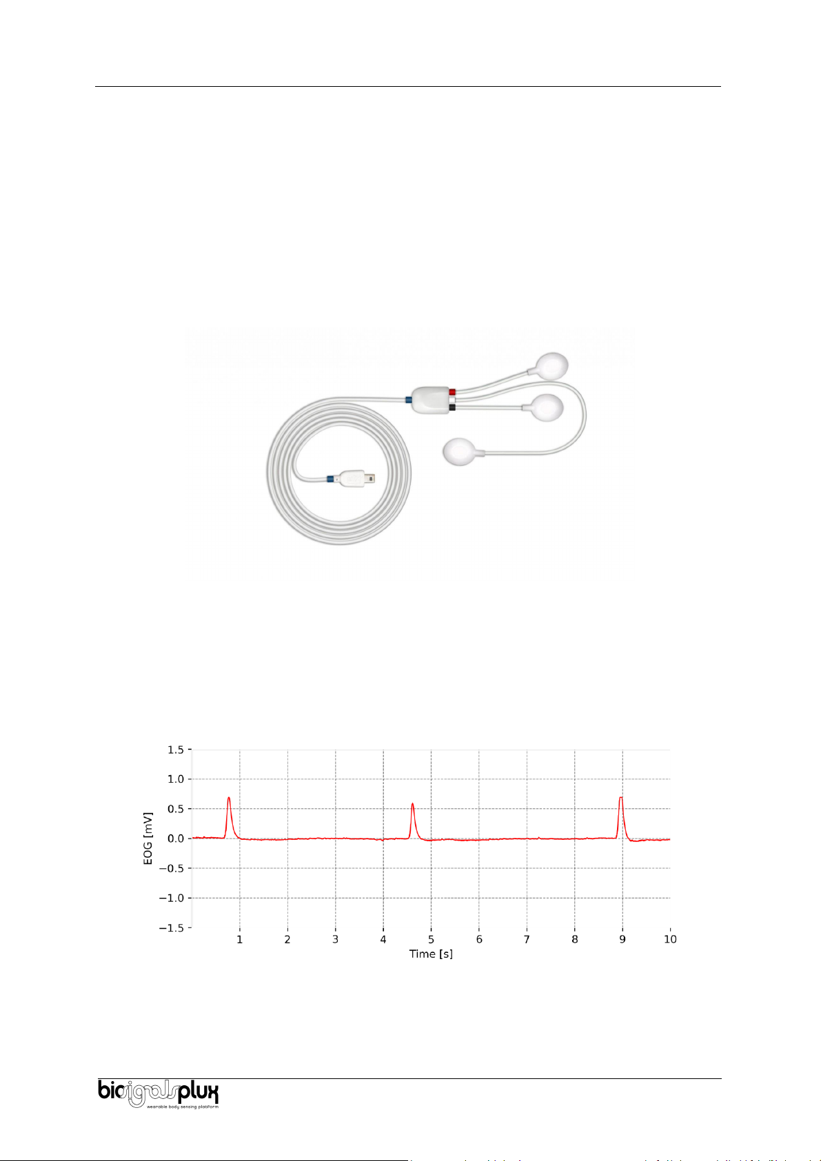
The biosignalsplux Electrooculography (EOG) sensor has been specially designed for seamless EOG
data acquisition. Either used by itself or in combination with an eye tracker, our sensor can provide
additional insight into your subjects’ eye gaze patterns. The bipolar configuration, with two
measurement electrodes, detects the electrical potentials in the specific temporal or facial region of
choice, with respect to a reference electrode (placed in an area of low bioelectrical activity). The
resulting signal is the amplified difference between these two leads, eliminating the common
unwanted signals. Its convenient form factor enables a discrete application in the typical EOG
electrode placement locations.
Figure 1: biosignalsplux EOG sensor (standard version)
1.2. Typical Unfiltered Sensor Output
Figure 2 shows a typical unfiltered Electrooculography sensor output acquired while blinking. The raw
digital sensor values received from the biosignalsplux device ranged between 0 and 2n-1 (n=sampling
resolution) were converted into the original unit of measurement of this sensor (mV) using the transfer
function found in section Transfer Function (Conversion Formula).
Figure 2: Typical unfiltered sensor output (while blinking and the sensors positioned above and below the eye).

Electrooculography (EOG)
User Manual
5 of 17
1.3. Sensor Specifications
> Gain:
2040
> Range:
±0.81mV (with VCC = 3.3V)
> Bandwidth:
0.05-41Hz
> Consumption:
~3mA
> Input Impedance:
> 100 G
> CMRR:
100 dB
1.4. Features
>Single-channel sensor
> Unobtrusive & lightweight sensor
>Bipolar differential measurement
> Pre-conditioned analog output
>High signal-to-noise ratio
> Ready-to-use form factor
> Medical-grade raw data output
> Small form factor
> Raw data output
> Easy-to-use
1.5. Applications
> Life sciences studies
> Biomedical device prototyping
> Human-Computer Interaction
>Eye gaze analysis
> Neurofeedback
> Biofeedback
> Sleep studies
> Neurophysiology studies
> Psychophysiology
> Biomedical device prototyping
> Biomedical research
1.6. Transfer Function (Conversion Formula)
The analog sensor signals acquired with biosignalsplux devices are converted into digital values ranged
between 0 and 2n-1 (n=sampling resolution, usually 8-bit or 16-bit) and streamed in the raw digital
format.
In most applications, the original physical unit of the acquired EOG signal is preferred or required. The
raw digital sensor samples can be converted back into millivolt (mV) using the following formulas:
(1)
(2)
Valid sensor range: [-1.5mV, 1.5mV]
with: EOG signal in V
EOG signal in mV
Value samples from the sensor/channel (digital value)
Sampling resolution (default: 16-bit resolution (n=16), although 12-bit and
8-bit may also be found)
Operating voltage (3V when used with biosignalsplux)
Sensor gain (2040)

Electrooculography (EOG)
User Manual
6 of 17
1.7. Electrode Connections & Sleeve Color Meanings
Sleeve Color
Red
Black
White
Electrode Cable
+
-
Reference
See section 2 for more information on where to place the electrodes and to connect electrodes cables
for EOG acquisitions.
1.8. Physical Characteristics
> W1 x L1 x H1:
1.0cm x 1.8cm x 0.4cm
> W2 x L2 x H2:
1.5cm x 2.3cm x 0.4cm
> A1:
105.0±0.5cm
> A2:
28.0±0.5cm
> A3:
8.0±0.5cm
> A4:
28.0±0.5cm
> D:
0.4cm
> Available sleeve colors:
White, Black, Blue, Green, Red, Yellow, Gray, and Brown
Figure 3: Physical characteristics of the standard Electrooculography (EOG) sensor.

Electrooculography (EOG)
User Manual
7 of 17
2. Application Notes
The biosignalsplux EOG is designed to be used in, essentially, two configurations that may be
combined. Given its bipolar configuration, the measured signals correspond to the differential
between two electrodes given the reference electrode. The relative positioning of the two electrodes
(positive and negative) allows to infer about the eye movements, specifically, vertical or horizontal
movements.
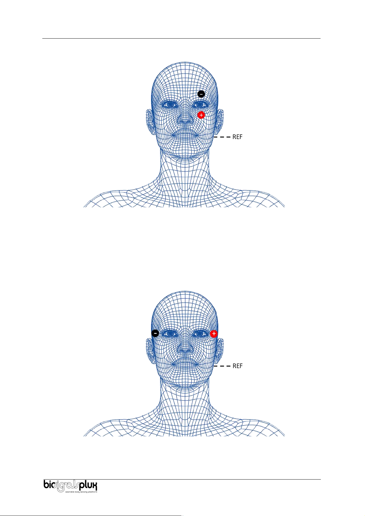
2.1. Reference Electrode
For the positioning of the reference electrode, it is recommended to be placed in an electrically neutral
spot in the body. For the EOG, it is common to place it as in Figure 4.
Figure 4 - Placement of the reference electrode.
To measure vertical eye movements, the electrodes should be positioned as illustrated in Figure 5. This
positioning allows the measurement of the difference of the potential between the above position and
under position of the eye, thus being indicated to measure the movements in that axis.
Electrooculography (EOG)
User Manual
8 of 17
2.2. Vertical Electrode Setup
Figure 5 - Placement of the electrodes to measure vertical eye movements.
For example, if the subject looks up, this will result in a positive peak in the signal, if the subject looks
down, this will lead to a negative peak. This way, the eye movement is aligned with the signal which
allows a more straightforward signal analysis.
The second configuration of the sensor is illustrated in Figure 6. This configuration is suited to measure
horizontal eye movements as it measures the difference between the potential of each side of the
eyes.
2.3. Horizontal Electrode Setup
Figure 6 - Placement of the electrodes to measure horizontal eye movements.
For example, if horizontal eye movement to the left triggers a positive peak, then horizontal eye
movement to the right triggers a negative peak. If we switch the leads, then this behavior will be
switched as well (left is now negative, right now positive).
Electrooculography (EOG)
User Manual
9 of 17
3. Using the Electrooculography (EOG) Sensor with biosignalsplux &
OpenSignals
3.1. Connecting the sensor to biosignalsplux Systems
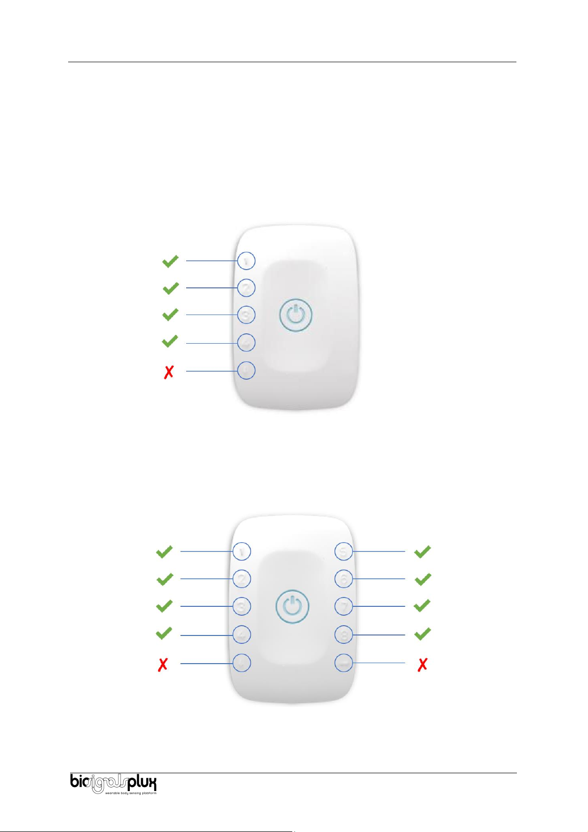
3.1.1. biosignalsplux 4-Channel Hubs
The biosignalsplux EOG sensor is compatible with all 8 analog input channels of the 4-channel
biosignalsplux hub, but incompatible with the reference/ground port. Connect the sensor to an analog
input to use it with this device.
Figure 7: EOG compatible biosignalsplux channels (green checkmarks).
3.1.2. biosignalsplux 8-Channel Hubs
The biosignalsplux EOG sensor is compatible with all 8 analog input channels of the 8-channel
biosignalsplux hub, but incompatible with the reference/ground and digital I/O ports. Connect the
sensor to an analog input to use it with this device.
Figure 8: EOG compatible biosignalsplux channels (green checkmarks).

Electrooculography (EOG)
User Manual
10 of 17
3.1.3. biosignalsplux Solo & Single-Channel openBAN Devices
The biosignalsplux EOG sensor is compatible with the analog input channel of the biosignalsplux Solo
(openBAN) device. Connect the sensor to the analog input channel to use it with this device.
Figure 9: Connect the EOG to the analog input channel of the biosignalsplux Solo (openBAN).
3.2. Configuring the Sensor in OpenSignals
3.2.1. OpenSignals (r)evolution (Windows, macOS, Linux)
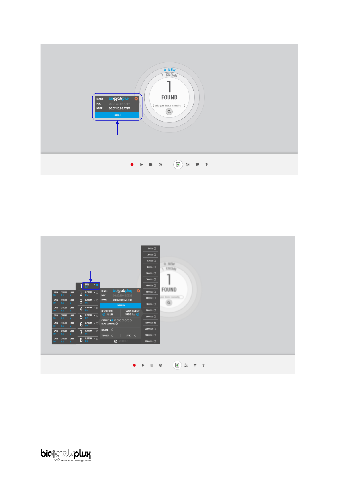
Open the OpenSignals (r)evolution device manager to access and configure your biosignalsplux device.
Figure 10: Access the OpenSignals (r)evolution device manager.
Select the device you intend to use for acquisition by clicking on ENABLE button on the device panel in
the OpenSignals device manager. The device is activated for acquisition if the ENABLE button is blue.
Electrooculography (EOG)
User Manual
11 of 17
Figure 11: Enabling the device for acquisition.
Click on the biosignalsplux logo to access the available settings. Select the channel your sensor is
connected to and select the RAW from the dropdown menu highlighted in the next screenshot, as the
EOG option is not yet available (after the acquisition, the acquired data should be converted to the
physical units using the above presented transfer function).
Figure 12: Set the channel type of the channel you have your EOG sensor connected to, to EOG.
Activate the channel for acquisition by clicking on the circle next to the channel type (must be blue). If
not done before, follow the instruction available in section 2. Application Notes to learn how to apply
the sensors and 3.1 Connecting the sensor to biosignalsplux Systems to learn how to connect your
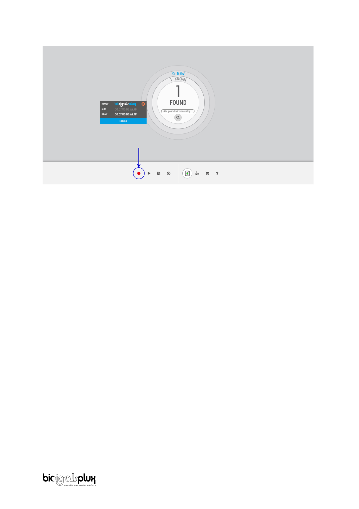
device to your biosignalsplux device. Click on the record button in the OpenSignals main interface
whenever you’re ready for your acquisition.
Electrooculography (EOG)
User Manual
12 of 17
Figure 13: Start the acquisition whenever you’re ready.

Electrooculography (EOG)
User Manual
13 of 17
4. Safety & Maintenance
4.1. Safety Instructions
Please read the following safety instructions before using your biosignalsplux system with the EOG
sensor to prevent any damages or problems with the user, test persons and/or biosignalsplux devices.
Violations of these instructions can lead to inferior signal quality and/or damages to the biosignalsplux
system and user.
!
The user should always keep the device and its accessories dry.
!
The user must turn off the biosignalsplux device and contact Technical Support if the system or
accessories reach uncomfortable temperatures.
!
The user should not use the biosignalsplux device in noisy environments (environments with
microwaves and other similar equipment). Doing so will lead to noise increase in the acquired
signals and Bluetooth connectivity issues.
!
The user must not use the device near the fire or in potentially explosive atmospheres, such as
atmospheres with flammable gas.
!
The user should only use the detection surfaces or other approved accessories purchased from
PLUX or by a PLUX agent.
!
The user should inspect the sensors on a regular basis to ensure that they remain in good
working order.
!
The user should stop using the biosignalsplux device if experience any kind of discomfort or
skin irritation.
!
Do not use the system on persons with allergies to silver.
!
The user should dispose detection surfaces after using the biosignalsplux device. Detection sur-
faces are single-user and disposable. Reusable electrodes should be reused by the same user.
Do not use reusable electrodes on several users.
!
The user must not place the device in the microwave.
!
The user must not insert objects into the holes of the device.
!
The user should not open the biosignalsplux device or its accessories. The repair of the same
should be only done by properly authorized PLUX personnel.
!
The user should make sure the cables do not obstruct the passage of people.
!
The user should use the sensor cables with extreme caution to avoid risk of strangulation.
!
The user should keep a safe distance between the biosignalsplux device and other devices to
ensure their proper functioning.
!
The user should only send the device to repair to qualified PLUX personnel.

Electrooculography (EOG)
User Manual
14 of 17
!
The user should not immerse the sensors or the biosignalsplux device, nor clean with liquid or
abrasives.
!
The user should handle the biosignalsplux device with caution and not expose the device or
accessories to high accelerations and vibrations.
!
biosignalsplux devices should not be used in patients with implanted electronic devices of any
kind, including pace-makers, electronic infusion pumps, stimulators, defibrillators or similar.
!
Do not apply electrodes over damaged or irritated skin.
!
Do not use your device while charging its internal battery.
4.2. Transportation and Storage
Please follow these recommendations to ensure safe transportation and storage of your biosignalsplux
equipment and sensors to prevent any damaging of your system.
The biosignalsplux equipment and sensors should be stored in the original box in a dry place when
those are not being used.
•Relative humidity: up to 95% with no condensation
•Ambient temperature: 10°C to 30°C
•Atmospheric pressure between 500hPa and 1060hPa
Whenever the equipment needs to be transported, it should be placed in the original box, since this
was designed and tested to ensure the equipment and accessories are securely stored.
Take care while handling the transportation of the system and avoid dropping it, since the device is
not shock-proof and should not be placed under stress or sudden acceleration.
4.3. Cleaning
Please follow these cleaning instructions to prevent any damage of the system or the user because of
conducting cleaning methods that may cause any damage.
•The biosignalsplux and sensors should be visually checked before each use and cleaning
process to ensure that no mechanical damage occurred.
•The biosignalsplux equipment and sensors (including the cables) should be cleaned with a
slightly damp cloth or suitable absorbent paper, ensuring no liquid enters the equipment of
sensors. Do not use detergent or any type of cleaning liquid as these may damage your
equipment and/or sensor.
•Do not clean or re-use detection surfaces (electrodes). They are only suitable for single use,
and should be disposed of after usage except indicated otherwise.

Electrooculography (EOG)
User Manual
15 of 17
5. Ordering Guides, Regulatory & Legal Information
5.1. Ordering Guide
Please follow the following ordering guide when submitting orders of EOG sensors to
[email protected]. If no specification is provided, the standard version of the sensor will be delivered.
Electrooculography (EOG) Sensor
SKU Reference
PLUX Code
UPC
SENSPRO-EOG
820201234
785614265143
Description
Electrooculography (EOG) sensor with standard physical characteristics and a random cable sleeve
color.
Electrodes & Accessories
For a full list of available and compatible electrodes, please visit the biosignalsplux store.
5.2. Guarantee of Quality & Warranty
biosignalsplux sensors have three months quality guarantee from the date of purchase. PLUX
guarantees that the system, sensors and accessories will be free from material or manufacturing
defects for the mentioned time periods following date of purchase.
If PLUX receives notification of any such defects within the guarantee period, it will repair or substitute
with the same unit\model, any products with proven defects at no cost to the client. During the repair
period PLUX promises to provide a temporary replacement under the same specification. Repairs will
be carried out at PLUX’s premises after the equipment has been received.
5.3. Warranty Voidance
Usage of the device that is not in accordance with the handling instructions indicated in the manual,
or use with accessories other than those manufactured by PLUX will invalidate the warranty of your
devices.
Be careful when connecting your biosignalsplux devices, sensors and/or accessories to any third party
device including the usage of the 3rd party connection components that are available for
biosignalsplux systems as the usage of these components will void the electrical warranty of your
biosignalsplux device and sensors and, if not indicated otherwise, the warranty of the 3rd party
system you’re connecting to the device. Check the electrical specifications of both systems you want
to connect to prevent any damage of the user(s) or the systems.
In the case of warranty voidance, the same applies that we expressly disclaim any liability whatsoever
for any direct, indirect, consequential, incidental or special damages, including, without limitation, lost
revenues, lost profits, losses resulting from business interruption or loss of data, regardless of the form
of action or legal theory under which the liability may be asserted, even if advised of the possibility of
such damages.
5.4. Contact & Support
Contact us if you are experiencing any problems that cannot be solved with the information given in
the biosignalsplux documentation.
Please send us an e-mail with precise information about the error occurrence, device configuration,
and, if possible, screenshots of the problem to support@plux.info.

Electrooculography (EOG)
User Manual
16 of 17
5.5. Regulatory Disclaimer
biosignalsplux products are intended for use in life science education and research applications; they
are not medical devices nor are they intended for medical diagnosis, cure, mitigation, treatment or
prevention of disease. we expressly disclaim any liability whatsoever for any direct, indirect,
consequential, incidental or special damages, including, without limitation, lost revenues, lost profits,
losses resulting from business interruption or loss of data, regardless of the form of action or legal
theory under which the liability may be asserted, even if advised of the possibility of such damages.

Electrooculography (EOG)
User Manual
17 of 17
PLUX Wireless Biosignals S.A.
email: [email protected]
web: http://www.plux.info
Headquarters
Zona Industrial das Corredouras, Lt. 14 –1°
2630-369 Arruda dos Vinhos
Portugal
tel.: +351 263 978 572
fax: +351 263 978 902
Lisbon Office
Av. 5 de Outubro, n° 79 –8°
1050-059 Lisboa
Portugal
tel.: +351 211 956 542
fax: +351 211 956 546
This manual suits for next models
2
Table of contents
Other biosignalsplux Medical Equipment manuals

Popular Medical Equipment manuals by other brands

REH4MAT
REH4MAT BODYMAP user manual

Buffalo filter
Buffalo filter PlumeSafe Wisper 602 Service manual

Alpha Modalities
Alpha Modalities A-Limb quick start guide

Innovo
Innovo INV-430J/PE user manual

Braun
Braun Aesculap Quintex Instructions for use/Technical description

Bioness
Bioness NESS L300 Plus user guide


