50
40
30
20
10
0
-10
-20 0 20 40 60 80
Cup inclination (°)
Cup anteversion (°)
Safe zone?
Safe zones
There have been various attempts to define a ‘safe
zone’ for the orientation of an acetabular cup, and
increasing evidence to suggest that one generic
zone is not applicable5,6,7,8,9.
Pelvic tilt
Pelvic tilt is an important consideration for
a patient's physiological profile, and the arc of
pelvic motion in some patients can be as mobile
as 70° and in others as stiff as 5° during functional
activities1,10. This can have significant impact on the
functional orientation of the acetabular cup.
What is the optimal cup orientation for an
individual patient?
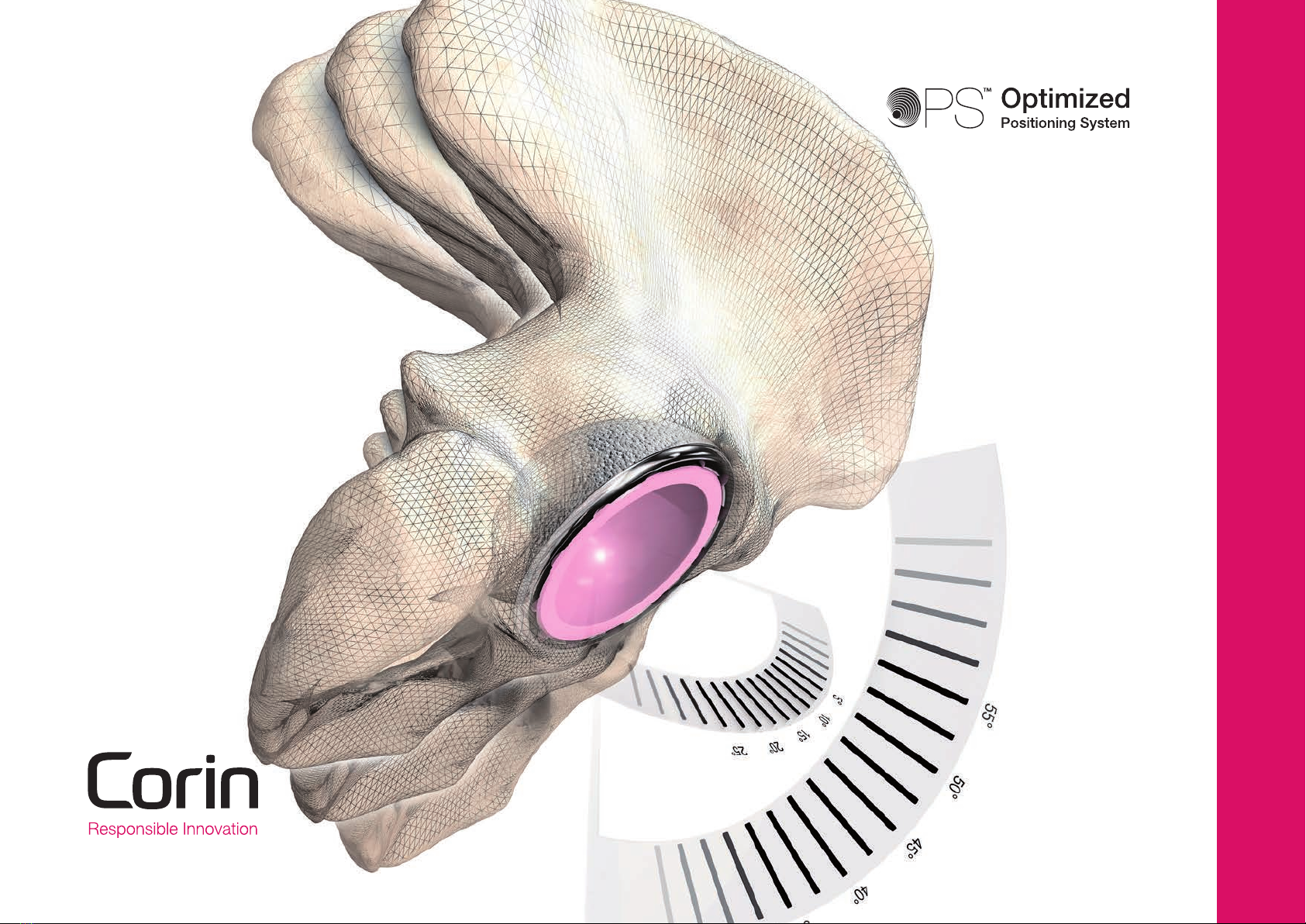
OPS™ is a state-of-the-art technology platform that
delivers potential target orientations unique for each
individual. These target orientations are calculated
from a dynamic pre-operative functional simulation,
which accounts for the patient's physiological profile
throughout a range of daily activities.
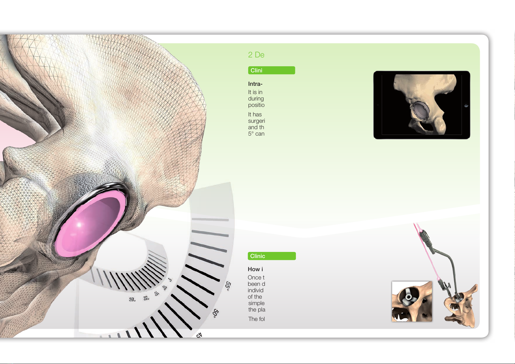
Clinical issue
Clinical solution
Overview
Every patient moves differently1and their total hip
replacement should be optimised to account for this.
The orientation of the acetabular cup is one of the
most important factors under the surgeon's control2,
and acetabular cup orientation has a significant
effect on device performance, including patient
outcomes, impingement, edge loading, bearing
wear, osteolysis and loosening3,4.
There remains two key issues with THR today:
What is the target for a well orientated cup?
Are we able to achieve that orientation?
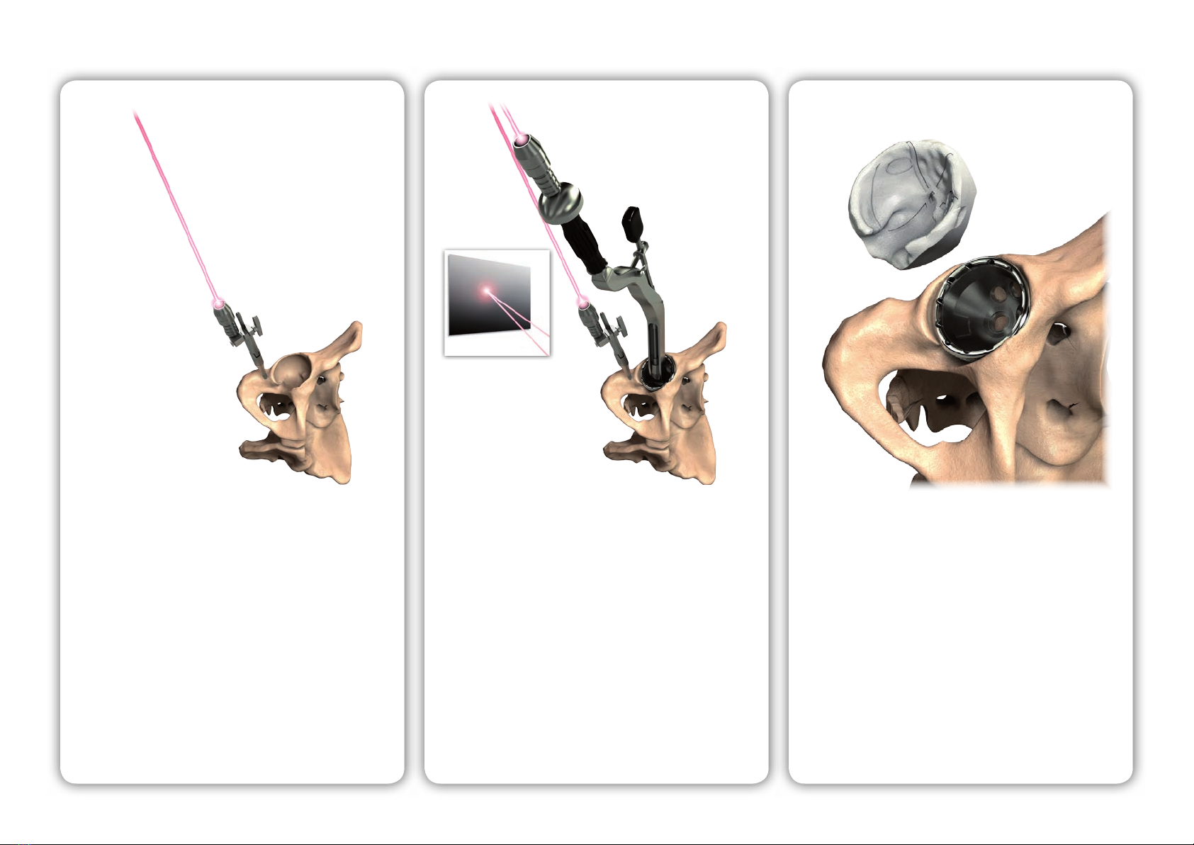
1
2
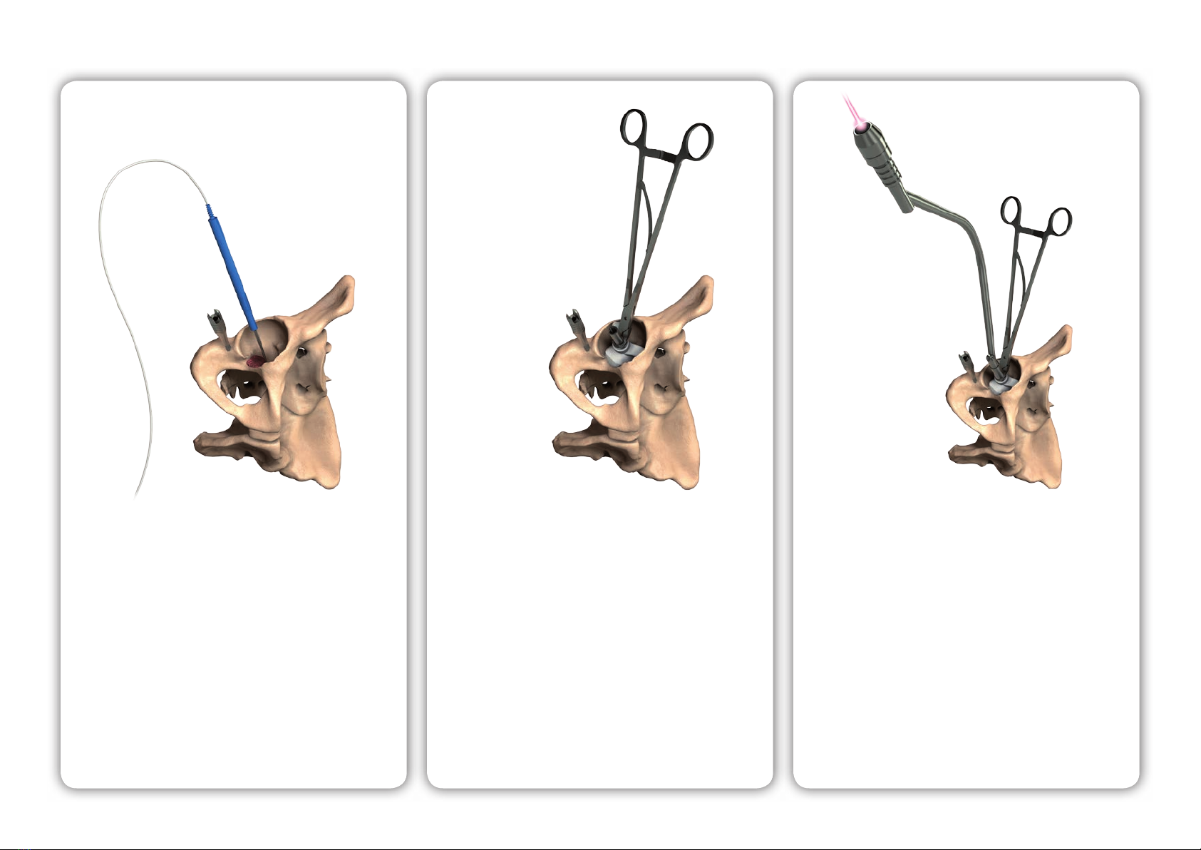
1 Implant orientation
Figure demonstrating the variation in pelvic tilt (anterior red, posterior
blue) for 100 patients throughout a range of daily activities. The variance
observed can be greater than 70°.
0 5 10 15 20 25 30 35 40 45 50 55 60 65 70 75 80 85 90 95 100
Patient number
30
20
10
0
-10
-20
-30
Degrees
Get the full picture. Scan to view
the OPS™ introductory video.
2