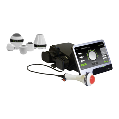
Biospace InBody 720 User manual

User s Manual

1996-2005 Biospace Co., Ltd. All rights reserved.
This user s manual cannot be copied, translated or transformed into different
media without a prior written consent from Biospace Co., Ltd, according to the
copyright laws. This user s manual and product pertinent to this manual may
have misprints or technical flaws, which can be modified without prior notice to
the readers. Biospace is not liable for any damage caused by a failure to meet
the requirements in this user s manual.
Biospace Co., Ltd.
10th Floor, Poonglim Bldg., 823 Yeoksam 1-dong, Gangnam-gu,
Seoul 135-784 KOREA
TEL : 82-2-501-3939 FAX : 82-2-501-3978
Homepage : http://www.biospace.co.kr
Biospace, InBody, Salus, Lookin Body are the registered trademarks of Biospace
Co., Ltd. The names of the companies and products in this manual other than those
of Biospace Co., Ltd. are the trademarks of the companies. Stating the products of
other companies is strictly for the purpose of providing information, and not to
guarantee or recommend the products. Biospace is not responsible for the
performance or the use of these products.
Biospace reserves the right to modify the dimensions or exterior of InBody720 to
improve the quality of the products, without consent of the customer.
BM-ENG1-27-B-050817

HOW TO USE THIS MANUAL
This user s manual explains the functions of InBody720 in the way that is very
detailed and easy to understand. Follow the instructions below for effective use
of this manual.
1. Read this manual thoroughly before using the equipment.
2. Take a few moments to look at the pictures of diagrams of the equipments to
understand the configuration of the equipment.
3. Read the Chapter 4 Problems and Solutions before requesting a warranty service.
4. Read the Chapter 5 Consumables when you want to purchase supplies or
optional devices.
5.
Email or phone us if you experience any inconvenience when using the equipment.
Forward any clinical inquiries at:
6. Read signs of warning, precautions and notes carefully. The followings are the
visual representations of these signs.
Important information to warn you of situations which might cause an imminent risk of death and/or major
injury if instructions are not carefully followed.
Important information to warn you of situations which might cause major injury and / or damage to property
if instructions are not carefully followed.
Important information to warn you of situations which might cause minor injury and / or damage to property
if instructions are not carefully followed.
Important helpful information for operating InBody720.

SAFETY INFORMATION
The following is important information to warn you of situations which
might cause an imminent risk of death and/or major injury if instructions
are not carefully followed.
1. Never use this unit in combination with the following medical electronic device.
- Medical electronic implants such as pacemakers
- Electronic life support systems such as an artificial heart/lung
- Portable electronic medical devices such as an electrocardiograph
- This equipment may cause the above mentioned medical electronic devices
to malfunction
2. Do not operate within 1 meter from shockwave or microwave therapy
equipment. Avoid simultaneously connecting patients to InBody720 and high
frequency surgical equipment.
The following is important information to warn you of situations which
might cause major injury and / or damage to property if instructions are
not carefully followed.
1. Do not operate within 1 meter of other running medical electronic equipment.
This will result in electromagnetic interference or possibly other interference
between InBody720 and that equipment.
2. To prevent fire caused by electricity, always use the standard fuse.
3.
To avoid electric shock, be sure to avoid contact between InBody720 and any kind
of external connector or other device that might be connected to a power source.
4. Do not operate this equipment if it has a damaged power cord or plug, if it is
not working properly, or if it has been damaged.
5. Do not immerse power cord in water.
6. Do not touch signal parts for external communication such as the parallel port,
a serial port, etc. and a human body at the same time.
7. Do not dismantle the equipment. Internal parts are not for customer use. If the
unit is dismantled, the warranty is void, and service costs will be charged to
you. If service is required, contact Biospace or the supplying agency.
8. Individuals with any kind of contagious disease or any kind of injury to the
palm or sole must not use or come in contact with this product.
9. Never start weight reduction or exercise therapy without the instructions of a
physician or a specialist. Self-diagnosis may damage your health condition.
Consult with your physician before using when pregnant.
10. This equipment is specifically designed to analyze body composition. Use the
equipment only for its intended use as described in this manual.

The following is important information to warn you of situations which might
cause minor injury and / or damage to property if instructions are not carefully
followed.
1. While moving, installing or using this product, be sure to protect it against any
physical shock or damage. Always use the packing material and the original
shipping carton when moving or transporting this product.
2. Always operate this product within prescribed ranges of temperature, humidity,
and pressure. Operating in ranges outside of those specified may affect the
operation of this product, and may cause malfunction.
3. Follow local governing ordinances and recycling plans regarding disposal or
recycling of device components.
4. Be careful not to spill or drop any residues of food or beverages on this
product. It may cause serious damage to the electronic components.
5. Install or locate the equipment only in accordance with the provided installation
instructions.
6. Do not use this equipment near water.
7. This equipment should be serviced only by qualified service personnel.
Contact Biospace for examination, repair or adjustment.
Important helpful information for operating InBody720.
1. This equipment generates, uses and can radiate radio frequency energy and if
not installed and used in accordance with the instructions, may cause harmful
interference to other devices in the vicinity. However, there is no guarantee that
interference will not occur in a particular installation. If this equipment does
cause harmful interference to other devices, which can be determined by
turning the equipment off and on the user is encouraged to try to correct the
interference by one or more of the following measures:
- Reorient or relocate the receiving device.
- Increase the separation between the equipment.
- Connect the equipment into an outlet on a circuit different from that to which
the other device(s) are connected.
- Consult the manufacturer or field service technician for help.
2.
This product has been designed, manufactured, and inspected under the full
quality assurance system of Biospace. Biospace fulfills European MDD ( Medical
Device Directive ), and InBody720 has acquired the CE conformity marking.
3. InBody720 fulfills the Standards of IEC60601-1 (EN60601-1), Safety of
Electric Medical Equipment. In addition, InBody720 complies not only with the
Level A for Noise Immunity but also with Level A for Noise Emission by the
Standard IEC60601-1-2 (EN60601-1-2), Electromagnetic Compatibility
requirements.
INDICATION & SAFETY SYMBOLS
A. Indication
Manufacturing Year
9pin serial port, (RS232C, Male)
Ethernet port (10/100Base-T)
USB port (Version 1.1)
IEEE 1284 (25pin Parallel), Female (PCL 3, or above; printer)
B. Safety signs
Dangerous high voltage
Danger / Warning /Caution / Note(refer to the safety information)
Fuse specification
Equipotential terminal
BF type equipment
Alternating Current
Turn on the power
Turn off the power
2005

INTRODUCING InBody720
THE BODY COMPOSITION ANALYZER.
Human body consists of body water, protein, body fat and mineral. The four
elements are the fundamental ingredients constituting the body and the balance
between them is essential to our health. Body composition analysis is to quantify
and measure these ingredients.
In the past, diagnosing obesity was focused on how we looked outside, without
considering the balance among body water, protein, body fat and minerals. From
the health point of view, body composition analysis that takes into account the
balance between body water, protein, body fat and mineral makes more sense
than diagnosing obesity based on how we look. In addition, this is where the
body composition analyzer with high precision comes in.
Biospace earned recognition in the international market for technical expertise
demonstrated through InBody 2.0 and 3.0. Based on the experience and
technicality accumulated over the last 10 years, Biospace released the
InBody720, taking the body composition analysis to a new height. The body
composition analyzer InBody720 is accurate for all body types and for any
possible distribution of body water, measuring the progress of clinical treatment,
weight loss program or exercise therapies reliably.
Using a diverse range of frequency from 1kHz to 1MHz, the InBody720
measures the amount of body water accurately. Particularly, the InBody720 is
the first version to use the reactance analysis method, which is the more
advanced technology for the body composition analysis than those used in
previous versions. Professional-looking exterior, high-definition monitor and new
level of expandability of the InBody720 that were not found in the previous body
composition analyzers will usher you into a new chapter of body composition.
Biospace strives to be your partner for health. We are committed to developing
high-quality products through transparent management and continuous research
and development.
Kichul Cha, CEO

CONTENTS
HOW TO USE THIS MANUAL
SAFTY INFORMATION
INDICATION & SAFTY SYMBOLS
INTRODUCING InBody720 - THE BODY COMPOSITION ANALYZER
Chapter 1 Installation and Maintenance
1. Contents in a Carton 1-2
2. Exterior and Functions 1-4
3. Installation Instructions 1-10
4. Transportation 1-12
5. Repacking 1-13
6. Maintenance 1-13
Chapter 2 Management & Results Description
1. Cautions Before Measurement 2-2
2. Exterior and Function of Keypad 2-3
3. Power Connection & Getting Started 2-4
4. Initial Screen and Input 2-6
5. Personal Profile 2-7
6. Proper Posture 2-9
7. How to Operate the Equipment 2-11
8. Results 2-14
Chapter 3 Setup Establishment
1. Setup Menu 3-2
2. Quick Setup 3-6
3. DATABASE 3-7
4. Modification Example 3-8
Chapter 4 Problems and Solutions
1. Error Messages 4-2
2. Trouble Shooting 4-3
3. Frequently Asked Questions ( FAQs ) 4-5
4. Customer Service Information 4-7
Chapter 5 Consumables
1. Consumables 5-2
2. Basic Equipment 5-3
3. Options 5-4
Appendix
1. More About InBody720 Appendix-2
2. Classifications Appendix-4
3. Specification Appendix-5
4. Worldwide Patents Appendix-6
LIMITED WARRANTIES Appendix-7

1. Contents in a Carton
2. Exterior and Functions
3. Installation Instructions
4. Transportation
5. Repacking
6. Maintenance
Chapter 1 Installation and Maintenance

1. Contents in a Carton
This product consists of the following units. Make sure your products include all
the units.
A. Product units
InBody720 equipment
Hinge cover + pentagonal wrench (6mm) 1 each
Fuse holder (1 unit) + fuse (F2.5AL250V; 2 units) + spare fuse 4 units
Cables (AC 250V 10A 1.8m)
The user s manual CD + Easy Installation Manual 1 each
Main Body Cover 1 unit(option)

B. Package
Pakaging Box(1250 450 280; mm, W L H) 1 unit
Support pad I 2 units
Support pad II 2 units
Loadcell pad 1 unit
Main body cover 1 unit
Hand electrode holder 2 units
Elastic band 2 units
Hand electrode bag 2 units
Fixed string 2 units
Head pad 2 units
Hinge pad 2 units
Accessory bag 1 unit
To reduce the physical impact on the equipment, use the wrapping material provided by the Biospace during
shipment or transit. For information on how to relocate the equipment, refer to the Chapter1, Section 4.
Transportation.
Keep the wrapping material with you after installation in the event of relocation.

2. Exterior and Functions
This section introduces the name of parts and their functions. Before installation,
check for cracks on the case of equipment.
A. Control Part
B. Upper Part
C. Lower Part
D. Rear Part
Control Part
Upper Part
Lower Part
Rear Part

A. Control part
LCD monitor (640 X 480 TFT Color LCD)
The monitor displays the status of
progress, message or test results.
Keypad (20 buttons)
The keypad is divisible into input buttons
and function buttons.The buttons are used
to input data required for body composition
analysis, set up the operating environment
or to print out test results.
B. Upper part
Hand Electrode Holder
Place the hand electrode while not in use.
Thumb Electrode
This is the area where the patients press their thumb on to come into contact
with electricity during testing.
Palm Electrode
The patients put their palm on this part to come into contact with electricity.
Hand Electrode Cable
The hand electrode cable is connected to the circuit that transfers voltage and
electric current.
Body Stand
The body stand contains the circuit board.
Palm Electrode Body Stand
Hand Electrode Cable
Thumb Electrode
Hand Electrode Holder

C. Lower part
Front Sole Electrode
The patient stands on the foot electrode to come into contact with electricity
during testing.
Rear Sole Electrode
The patient put their heels on this foot electrode to come into contact with
electricity during testing.
Base Frame (Loadcell)
The loadcell is connected to the base frame where the patient stands on.
Hinge Cover
The hinge cover with hinges in the middle separates the area connecting the
upper and lower part of the equipment. It can come off the equipment and be
folded into half for easy transportation. A body wrench (6mm) is attached
underneath the hinge cover.
Level Indicator
The level is in the middle of the lower part, which is covered by the hinge
cover. Check out with the level to determine whether the equipment is level.
Leveling Screw
The equipment has five legs screwed into the equipment. You can use the
legs to adjust the height and level of the equipment.
Front Sole Electrode
Leveling Screw
Level Indicator
Base Frame
Rear Sole Electrode
Hinge Cover
Bubble
Level

D. Rear part
(1) Back Cover
The back cover should be opened only for the purpose of repair. Only the
Biospace technicians are allowed to open the cover.
Biospace is not responsible for damages done on the product or injury caused by the user s unauthorized
opening of the back cover.
Biospace is not responding to any request for repair or upgrade, when damage is done on the warning
sticker or there is any indication that the back cover was previously opened. Do not open the back cover in
any case.
(1) Back Cover
<Warning sticker>

(2) Control & Connection Unit
This unit allows the equipment to connect to peripherals such as computers
and printers as well as transferring data back and forth.
9pin Serial Port, Male (RS-232C)
Com 1 port is used to connect to the personal computer that runs the Lookin Body.
Com 2 port is used for an additional peripheral.
Com 3 port is used to hook up the automatic blood pressure monitor provided by the Biospace.
LAN Port (10/100 Base-T)
Through LAN cable, the equipment can communicate with the external systems including
computers. The LAN interface supports both 10Mbps and 100Mbps Ethernet connection.
USB Port (Version 1.1)
InBody720 communicates with external devices such as computers and printers through
the two USB ports and cables. You can use either of the two USB ports
interchangeably. As of now, the equipment supports only printers as a USB device.
25pin Parallel Port (IEEE 1284)
The 25pin parallel port is used to connect to printer. If you intend to use USB printer,
connect it to the USB port.
Only the peripherals provided by Biospace can be connected to InBody720. For any inquiry about
peripherals, contact Biospace.

(3) Power & Safety Unit
Power Socket
Plug the 3-pin plug to the power socket to supply the power to the equipment.
Fuse Socket
The fuse holders (two fuses) are embedded in the equipment.
Equipotential Terminal
The equipotential terminal can be connected to the external equipotential line to
prevent danger caused by the difference in the potentials between the other devices.
Power switch

3. Installation Instructions
A. Workplace Reguirements
(1) Location: Indoor only. Any outdoor area where the equipment is to be located
should meet all the environmental requirements.
(2) Operating environment: 10 ~40 (50 ~ 104 ), 30%~80% RH
(3) Power supply: 100 - 240V~, 50/60Hz
B. Unpacking and Assembling
(1) Put down the packaging box on where the equipment will be located with the
written instructions on top. Open up the top and take out the accessory bag.
(2) Remove hinge pads in the corners and put up the upper part of the
equipment.
(3) Remove the loadcell pad and the cover of the equipment.
(4) Remove the elastic band that pulls the hand electrode cables together and
then the holder for hand electrode.
(5) Lift up the back of the lower part of the equipment gently to remove the
support pads at the back.
(6) Before taking out the equipment, tighten up the screws connecting the upper
and lower part with a box wrench. The box wrench is attached to a tape
underneath the hinge cover.
(7) Hold the bottom of upper part and the center of lower part on both sides with
hands and take the equipment out of the box. Take the equipment to where it
will be installed.
(8) Tighten up the four screws connecting the upper and lower part with the box
wrench.
(9) Adjust the height of equipment using the four legs attached to the lower part
of the equipment and one leg from the upper part of the equipment. Keep the
equipment level, using the level indicator located at the center of the
connection unit.
<Raise up> <Raise down>

(10)
Attach the box wrench back to the underneath the hinge cover and put the hinge
cover back over the connection area between the upper and lower part.
(11) Plug the fuse holder containing the fuse into the fuse socket and then plug in
the power to the power socket.
(12)
Put a spare fuse in a small plastic bag and attach it to the back of the equipment
with tape. When the fuse is brown, you can replace it with the spare fuse. Refer
to the Chapter 5 Consumables for specifications of fuse.
Put the main body cover over the equipment, if you don t use it for an extended period of time.
<Un - Leveled State > <Leveled State>

4. Transportation
It is best not to move the equipment around once it is installed. If it is inevitable to
relocate the equipment, follow the safety requirements that follow.
(1) Turn the power off and pull the plug off the power outlet before moving.
(2) Take all the possible measures to ensure no physical impact is made on the
hand electrode.
(3)
Adjust the level of the equipment using the legs of the equipment after moving.
(4)
Tighten the connection between the lower and upper part with the body wrench
.
A. Environmental requirements
Temperature: 0 ~40 (32 ~104 )
Relative humidity: 30% ~80%
Air pressure: 500hPa~1060hPa
B. Transporting before installation
Before installation, the equipment is in a packaging box provided by Biospace.
Use a carrier to move the box over or have two people move it from both sides
for safe transportation.
C. Transporting after installation
It is not recommended to move the equipment installed by Biospace or the
authorized distributors of Biospace. If it is inevitable to move the equipment,
repackage the equipment with the box and wrapping material the equipment
came in, to keep the equipment from being damaged during transportation.
After moving the equipment, adjust the level of the equipment using the level indicator and legs of the
equipment. The level of the equipment is crucial to accurate testing.
Table of contents