Biospherical Instruments Inc QSR-2200 User manual

QSR-2200 / QCR-2200 User’s Manual QSR_QCR2200_Manual.DOC
B
IOSPHERICAL
I
NS RUMEN S
I
NC
. i
QSR-2200
QCR-2200
Analog Quantum Reference Sensor
User's Manual
Biospherical Instruments Inc.
5340 Riley Street
San Diego, CA 92110-2621 USA
Phone: (619) 686-1888
Fax: (619) 686-1887
E-mail: support@biospherical.com
www.biospherical.com
Date Printed: 2/15/2011

QSR-2200 / QCR-2200 User’s Manual QSR_QCR2200_Manual.DOC
B
IOSPHERICAL
I
NS RUMEN S
I
NC
. ii
NO ICE
he information contained in this document is subject to change without notice.
BIOSPHERICAL INS RUMEN S MAKES NO WARRAN Y OF ANY KIND WI H REGARD O
HIS MA ERIAL, INCLUDING, BU NO LIMI ED O, HE IMPLIED WARRAN IES OF
MERCHAN ABILI Y AND FI NESS FOR A PAR ICULAR PURPOSE. Biospherical
Instruments shall not be liable for errors contained herein or for incidental or consequential
damages in connection with the furnishing, performance, or use of this material.
his document contains proprietary information which is protected by copyright. All rights are
reserved. No part of this document may be photocopied, reproduced, or translated into another
language without the prior written consent of Biospherical Instruments Inc.
Copyright 2011 by Biospherical Instruments Inc.
Document QSR_QCR2200_Manual.DOC
First Edition May, 2002

QSR-2200 / QCR-2200 User’s Manual QSR_QCR2200_Manual.DOC
B
IOSPHERICAL
I
NS RUMEN S
I
NC
. iii
LIMITED WARRA TY
LIMI ED WARRAN Y
BIOSPHERICAL INS RUMEN S INC. (the Company) warranties this instrument, system or
software (the Product) to function properly and be free of defects in materials for a period of
one (1) year and in workmanship for a period of ninety (90) days from the date of original
shipment from our factory. Should this Product fail to be in good working order at any time
during the above stated warranty period, Biospherical Instruments Inc. will, at its option, repair
or replace this Product at no additional charge except as set forth below. Repair parts and
replacement Products will be furnished on an exchange basis and will be either reconditioned or
new. All replacement parts and Products become the property of the Company. his limited
warranty does not include service to repair damage to the Product resulting from accident,
disaster, misuse, abuse or revisions made to the product by parties other than the Company.
Devices manufactured by other parties and delivered as part of the Product are warranted to
the extent and manner provided by the original equipment manufacturer. Repairs made by the
Company to its Products carry the same warranty as new products manufactured by Company.
Limited warranty service may be obtained by delivering the Product during the warranty period
to Biospherical Instruments Inc. at its San Diego, California, Service Center, showing proof of
purchase. he company reserves the right to charge a reasonable fee for services provided in
determining the nature of a malfunction and the preparation of a written repair estimate. If this
Product is delivered by mail, courier, or other public carrier you agree to insure the Product or
assume risk of loss or damage in transit; to prepay shipping charges to the San Diego,
California, Service Center; to use the original shipping container or equivalent; and to pay for
return shipping charges.
ALL EXPRESS AND IMPLIED WARRAN IES FOR HIS PRODUC INCLUDING HE
WARRAN IES OF MERCHAN ABILI Y AND FI NESS FOR A PAR ICULAR PURPOSE,
ARE LIMI ED IN DURA ION O HE ABOVE WARRAN Y PERIOD, AND NO
WARRAN IES, WHE HER EXPRESSED OR IMPLIED, WILL APPLY AF ER HIS PERIOD.
IF HIS PRODUC IS NO IN GOOD WORKING ORDER AS WARRAN IED ABOVE, YOUR
SOLE REMEDY SHALL BE REPAIR OR REPLACEMEN AS PROVIDED ABOVE. IN NO
EVEN WILL BIOSPHERICAL INS RUMEN S INC. BE LIABLE O YOU FOR ANY
DAMAGES, INCLUDING ANY LOS PROFI S, LOS SAVINGS OR O HER INCIDEN AL OR
CONSEQUEN IAL DAMAGES ARISING OU OF HE USE OR INABILI Y O USE SUCH
PRODUC , EVEN IF BIOSPHERICAL INS RUMEN S INC. HAS BEEN ADVISED OF HE
POSSIBILI Y OF SUCH DAMAGES. NOR WILL BIOSPHERICAL INS RUMEN S INC. BE
LIABLE FOR ANY CLAIM BY ANY O HER PAR Y.
SOME S A ES DO NO ALLOW HE EXCLUSION OR LIMI A ION OF INCIDEN AL OR
CONSEQUEN IAL DAMAGES FOR CONSUMER PRODUC S, SO HE ABOVE
LIMI A IONS OR EXCLUSIONS MAY NO APPLY O YOU.
HIS WARRAN Y GIVES YOU SPECIFIC LEGAL RIGH S, AND YOU MAY ALSO HAVE
O HER RIGH S WHICH MAY VARY FROM S A E O S A E.

QSR-2200 / QCR-2200 User’s Manual QSR_QCR2200_Manual.DOC
B
IOSPHERICAL
I
NS RUMEN S
I
NC
. iv
TABLE OF CO TE TS
TABLE OF CONTENTS
________________________________________________________ iv
INITIAL INSPECTION AND SHIPPING PROCEDURES
_____________________ v
PRECAUTIONS
_________________________________________________________________ v
1.0 INTRODUCTION
___________________________________________________________ 1
2.0 SPECIFICATIONS
_________________________________________________________ 1
2.1 QSR-2200 and QCR-2200 _______________________________________________________ 2
3.0 INSTALLATION, OPERATION, AND MAINTENANCE PROCEDURES
3
3.1 INSTALLATION ______________________________________________________________ 3
3.2 OPERATION _________________________________________________________________ 3
3.3 MAINTENANCE ______________________________________________________________ 4
APPENDIX: THEORY OF OPERATION
______________________________________
TECHNICAL DRAWINGS _________________________________________________________ 6

QSR-2200 / QCR-2200 User’s Manual QSR_QCR2200_Manual.DOC
B
IOSPHERICAL
I
NS RUMEN S
I
NC
. v
I ITIAL I SPECTIO A D SHIPPI G PROCEDURES
his instrument was carefully inspected mechanically and electrically, and was calibrated before
shipment. It should be free of mars or scratches and in perfect operating condition upon
receipt. o confirm this, the instrument should be inspected for physical damage incurred in
transit. If the instrument was damaged in transit, file a claim with the carrier. See Warranty in
the preface of this manual.
WARNING: Read the sections on installation, operation and maintenance
before attempting to operate or disassemble the instrument.
Retain original packing material for shipment to the factory. he instrument must be carefully
wrapped and cushioned with appropriate packing material before it is shipped.
PRECAUTIO S
PROTECT THE CABLE A D CO ECTOR. Avoid any sharp bends in the interconnect cable.
o ensure cable safety, secure the cable in place during instrument usage. he connector is
the most vulnerable part of the system. Protect the connector contacts from moisture, both
during use and while in storage. Do not step on the connector, or strike it while it is plugged
into the instrument.
PROTECT THE I TEGRATED CIRCUITS. A person walking across a carpet on a dry day can
generate a static charge of more than 10,000 volts. he resulting discharge can destroy an
integrated circuit. herefore, use standard anti-static equipment any time the instrument is
opened and the components are removed.
AVOID SHADOWS A D REFLECTIO S. During deployments or installations, be careful to
keep the instrument away from reflections and shadows caused by surrounding structures. An
underwater instrument package should be positioned for lowering on the side of the ship toward
the sun. If the instrument is lowered into the shadow created by the ship, this shadow will
contaminate measurements for depths up to 100 meters. When positioning a ship and
deploying an underwater sensor, the wind direction is also a factor since the wind or wind-
driven currents can push the ship over the sensor when it is being lowered, thereby causing
shadowing. A surface sensor should be mounted so that it will not be shaded by or experience
reflections from surrounding structures.
MAI TAI PROPER CALIBRATIO . he proper conversion factors for the sensor voltages to
engineering units are contained on the calibration certificate issued with the instrument, and are
updated on subsequent recalibrations. It is ultimately the user’s responsibility to ensure that the
proper calibration factors are used during data analyses. Any calibration factors published in
this manual are for example only; valid entries may be found on the calibration certificate
issued with each BSI instrument.
CARRY SPARE CABLE. For extended operations, it is prudent to carry spare cables.
PROTECT THE COLLECTOR. he eflon diffuser is a critical optical component of the
collector which is easily scratched or damaged. If you suspect damage, consult the factory.
Keep the irradiance diffuser as clean as possible by periodically wiping it with a damp cloth.

QSR-2200 / QCR-2200 User’s Manual
B
IOSPHERICAL
I
NS RUMEN S
I
NC
. 1
1.0 I TRODUCTIO
Biospherical Instruments Inc's Analog Quantum Reference
Sensors (QSR-2200 or QCR-2200) are designed as a surface
(non-submersible) instrument for monitoring total incident PAR
(photosynthetically active radiation, 400 nm to 700 nm) from the
sun and sky. hey are designed to be used primarily with C D’s
and dataloggers that require an analog voltage as signal input.
Biospherical Instruments also offers computer hardware and
software packages suitable for data logging and analysis using
this series of instruments – contact factory for details.
QSR-2200- he QSR-2200 is a hemispherical scalar reference
sensor. It shares the scalar directional response of Biospherical
Instruments’ QSP-2000 series of sensors, but it includes a field-
of-view cutoff plate that transforms its response to a
hemispherical one. he sensor produces an analog voltage
output that is directly proportional to the irradiance incident upon
the sensing plane of the collector. his sensing plane lies halfway
between the equator and upper pole of the spherical collector.
Due to geometric differences, data collected with a scalar sensor
is not easily compared with cosine irradiance measurements.
QCR-2200- he QCR-2200 is a PAR reference sensor that utilizes
a flat cosine collector design. It shares the cosine directional
response of Biospherical Instruments’ QCP-2000 series of aquatic
sensors. he sensor produces an analog voltage output that is
directly proportional to the cosine of irradiance incident upon the
collector. Note: Due to geometric differences, data collected with
this cosine sensor is not easily compared with scalar irradiance
measurements.
In order to fully understand the capabilities of the QSR-2200 and
QCR-2200, the user should read this manual carefully and
thoroughly. he manual includes operating instructions,
precautions, and compatibility notes that can help the user adapt
the instrument to a specific application.
2.0 SPECIFICATIO S
QSR-2200 SCALAR IRRADIANCE COLLEC OR: 1.9 cm (3/4")
diameter solid eflon
®
sphere optically connected to the main
housing by a 2.5 cm, stainless-steel encased quartz fiber.
QCR-2200 COSINE IRRADIANCE COLLEC OR: 1.15cm (.45”)
diameter, solid acrylic collector that is o-ring sealed.

QSR-2200 / QCR-2200 User’s Manual
B
IOSPHERICAL
I
NS RUMEN S
I
NC
. 2
QSR DIREC IONAL RESPONSE: Each instrument's directional
response is optimized before final calibration. he response is a
constant ±7%, between 0
o
to approximately 135
o
in zenith angle,
with response falling off to zero as the light field is obscured by
the instrument housing. Individual detector response plots are
available upon request.
QCR DIREC IONAL RESPONSE: Each instrument's directional
response is optimized before final calibration. From zenith angles
of 0° to 85°, the instrument’s directional response follows the
cosine law to ±6%.
2.1 QSR-2200 and QCR-2200
PHO ODE EC OR: Blue-enhanced high stability silicon
photovoltaic detector with dielectric and absorbing glass filter
assembly.
SPEC RAL RESPONSE: Constant (better than ±10%) quantum
response from 400 to 700 nm with response sharply attenuated
above 700 nm and below 400 nm. Spectral response induced
errors will cause less than ±5% errors in naturally occurring light
fields.
SENSI IVI Y: When purchased alone, the sensor is calibrated in
quanta /(cm
2
sec). Nominal sensitivity is 1 Volt = 6 x 10
17
quanta/(cm
2
sec) (slightly less than full sunlight). Noise level is
typically 1 mV (standard deviation).
OU PU POLARI Y: Goes more positive as irradiance
increases, and has a small positive offset (dark voltage).
CALIBRA ION: Calibrated using a National Institute of Standards
and echnology traceable 1000 watt type FEL Standard of
Spectral Irradiance. Annual recalibration is recommended.
OU PU IMPEDANCE: 100 ohms.
ENVIRONMEN AL: Fully sealed and water resistant, and it has a
special weather-proof connector. Its operating temperature range
is -15 to 35°C.
POWER REQUIREMEN S: 6-15 Volts DC and 0.9 to 4 mA is
required. ypically, power is supplied by the user’s C D or data
acquisition system. An external battery pack may also be used.
CABLE: QSC-2200 shielded, weather resistant cable (ordered
separately) is supplied with appropriate connectors.

QSR-2200 / QCR-2200 User’s Manual
B
IOSPHERICAL
I
NS RUMEN S
I
NC
. 3
3.0 I STALLATIO , OPERATIO , A D MAI TE A CE
PROCEDURES
3.1 I STALLATIO
he sensor should be installed in a place that is free of obstacles
that might block its field of view. he sensors have a large
mounting base with several holes so that it may be secured to a
variety of mounting platforms. When it is operated in high seas, it
may be necessary to gimbal mount the sensor to prevent the data
from changing rapidly, making it difficult to read and analyze.
Note that the QSR-2200 features a circular irradiance shield or
"cut-off plate" that blocks irradiance from the lower hemisphere of
the collector so as to permit monitoring of only total irradiance
from the sun and sky. he plane of the shield must be level with
the horizon and there should be no physical obstructions
(buildings, masts, etc.) above this plane. For special applications
this shield may be removed without otherwise affecting operation.
NOTE: o not attempt to remove the QSR’s
irradiance collector sphere.
When you initially receive your sensor and before leaving for the
field, you should fully connect the instrument and data acquisition
system you intend to use. Make certain that the system runs
properly. If it does not, consult the factory for assistance.
3.2 OPERATIO
Before deploying the sensor, you should place a dark cloth over
the sensor and take a “dark” or “zero” reading. With this
information, you can correct your data for any zero offsets.
If you are using a third-party device for collecting data, remember
that these sensors require 6-15 VDC at 0.9-4 mA. he sensor
normally outputs an analog signal between 1 and 5 volts for full
sunlight. Make sure that your data acquisition system meets
these requirements.
We strongly recommend that, whenever the instrument's
calibration is in question for any reason, the instrument should be
returned to Biospherical Instruments for recalibration and
examination at a nominal charge.

QSR-2200 / QCR-2200 User’s Manual
B
IOSPHERICAL
I
NS RUMEN S
I
NC
. 4
3.3 MAI TE A CE
QSR-2200 When the sensor is mounted outside for long periods
of time, it is important to periodically clean the collector. While
cleaning the QSR-2200 scalar sphere and shield, do not attempt
to rotate or remove the collector sphere or the calibration of
the sensor will be altered. o clean the spherical collector,
simply wipe it gently using a soft tissue or towel and warm water,
soap or alcohol. Do not use any other solvents such as acetone,
MEK, or richlor because these can dissolve the coatings on the
shield. Also, do not use acids, abrasive cleaners, or brushes as
this will mar the surface of the sphere and void the instrument's
calibration. Should the sphere become damaged or heavily
soiled, return the instrument to the factory for service and
recalibration.
If the surface of the irradiance shield becomes soiled and its
reflectance changes, the calibration of the instrument will be
altered. herefore, the user should keep the irradiance shield as
clean as possible by periodically wiping it with a damp cloth.
Remember to avoid moving or scratching the eflon
®
diffuser.
QCR-2200 he QCP’s acrylic cosine collector may only be
cleaned using a soft tissue or towel and warm water. Do not use
any solvents such as acetone or alcohol. hese chemicals will
discolor and soften the acrylic collector.
he only other maintenance procedures required by the
instrument are annual optical recalibrations and biannual
preventive maintenance checks. Consult your factory for details.

QSR-2200 / QCR-2200 User’s Manual
B
IOSPHERICAL
I
NS RUMEN S
I
NC
. 5
APPE DIX: THEORY OF OPERATIO
THEORY OF OPERATIO
QSR-2200 he eflon
®
sphere on the instrument serves as the irradiance collector. Light
penetrating the surface of the sphere is diffused as it passes toward the center. A quartz
optical conductor is inserted into the sphere to collect the diffuse light from the sphere and
guide it to the filter and detector assembly. he light travels through a special filter assembly
and onto a low noise silicon photodiode.
QCR-2200 he acrylic cosine collector diffuses light and directs it to a special filter assembly
and to a low noise blue-enhanced silicon photodiode.
In both models, an optical filter assembly adjusts the overall spectral response of the detector
and collector to give the instrument a constant quantum response between 400 nm and 700 nm
with negligible response outside this region.
he current from the photodiode is amplified and converted to a voltage by a high stability
electrometer amplifier in the sensor housing. he instrument also contains power
conditioning circuitry for generating the required amplifier supply voltages. he signals
from the amplifier are transmitted through the connector to your cable. Output voltages
from the sensor are DC voltages. Consult your calibration certificate for specific calibration
factors.
QSR-2200 / QCR-2200 User’s Manual
B
IOSPHERICAL
I
NS RUMEN S
I
NC
.
6
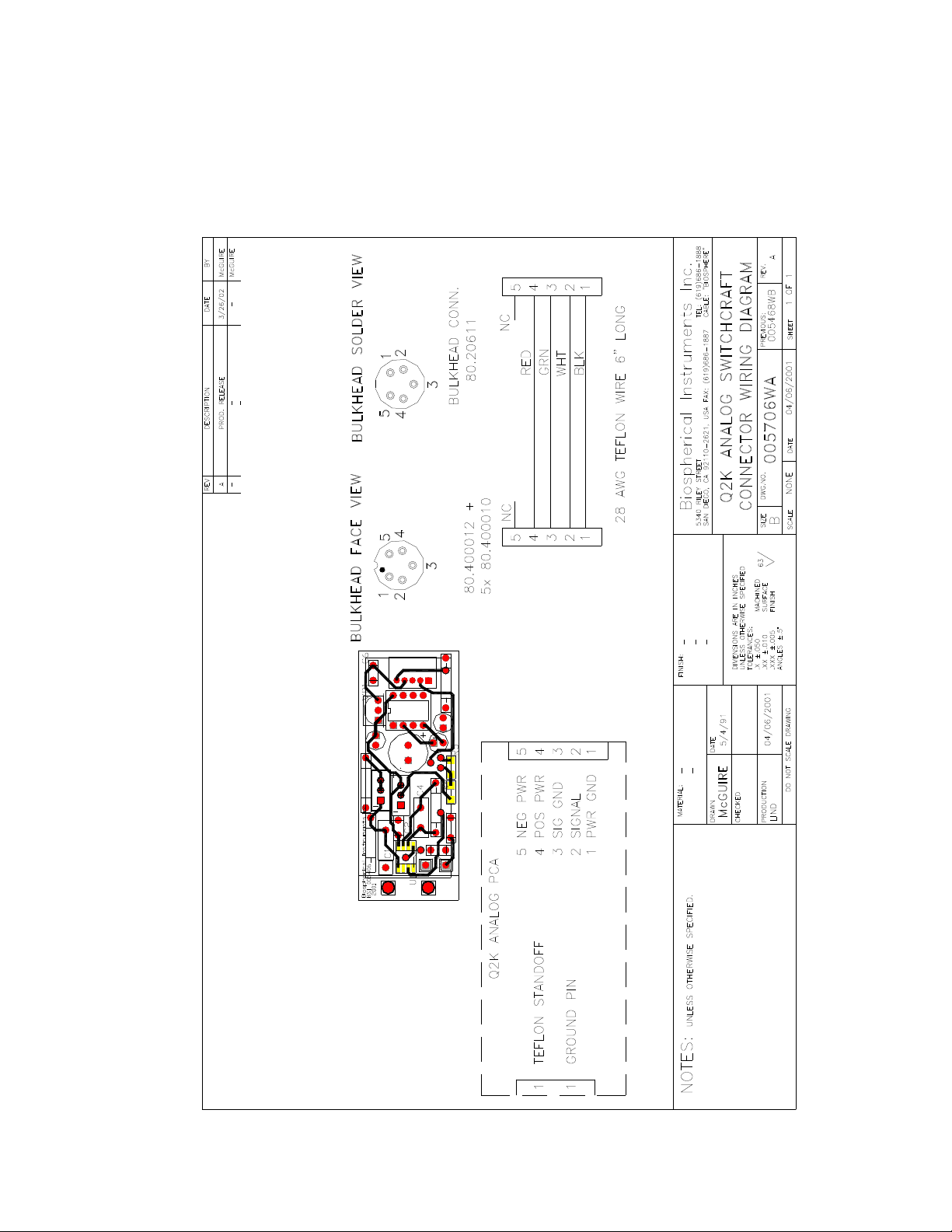
TECH ICAL DRAWI GS
Wiring arrangement for the Switchcraft connector used in these sensors
This manual suits for next models
1
Table of contents


