Bircher Reglomat ESR25 User manual

1
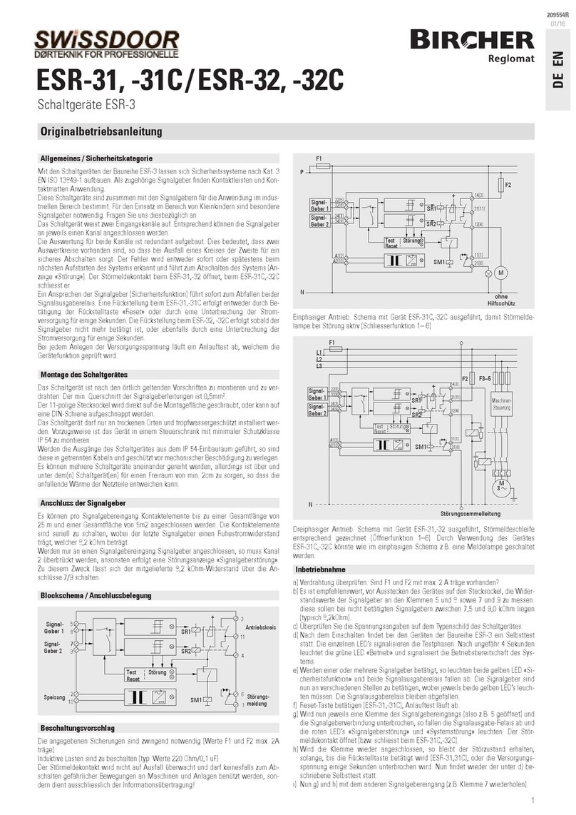
Montage, Inbetriebnahme, Periodische Tests
1. Widerstand messen, im nicht betätigten Zustand zwischen 8,1 kOhm und
8,6 kOhm (typisch 8,2 kOhm).
2. Verdrahtung überprüfen. F1 (ESR 26: F1 und F2) mit max. 2A träge be-
stückt?
3. Einschalten des Gerätes, bei Bereitschaft leuchtet die grüne LED (beim
ESR26 beide grünen LEDs) auf.
4. Signalgeber betätigen, die entsprechende gelbe LED leuchtet auf (beim
ESR26 beide gelben LEDs), die Ausgangsrelais fallen ab.
5. Klemme eines Signalgebers ist offen, so leuchtet die rote LED (beim ESR26
beide roten LEDs), die Ausgangsrelais fallen ab.
Wichtig:
Montieren und verdrahten gemäss örtlichen Vorschriften. Minimale
Querschnitt ist 0,14 mm2. Darf nur in IP54 Gehäuse eingebaut werden.
Für periodische Tests müssen die Kontakte J1 und J4 (beim ESR26 J2 und J3)
nacheinander überbrückt werden (siehe Bestückung). Jedes mal muss ein
Stop erfolgen. Der Test «Unterbruch» wird durch Lösen des Signalgebers er-
zeugt. Stop muss erfolgen. Es wird empfohlen, die Kontrollen zu protokollie-
ren.
Die Tests sind durch geschultes Personal mit einem Werkzeug mit
isoliertem Griff vorzunehmen.
ESR25/26
Schaltgeräte
Originalbetriebsanleitung
DEUTSCH
209491S
06/16
Allgemein
Das ESR25 und das ESR26 unterscheiden sich darin, dass das ESR26 zwei
getrennte Auswertekreise hat.
Funktion
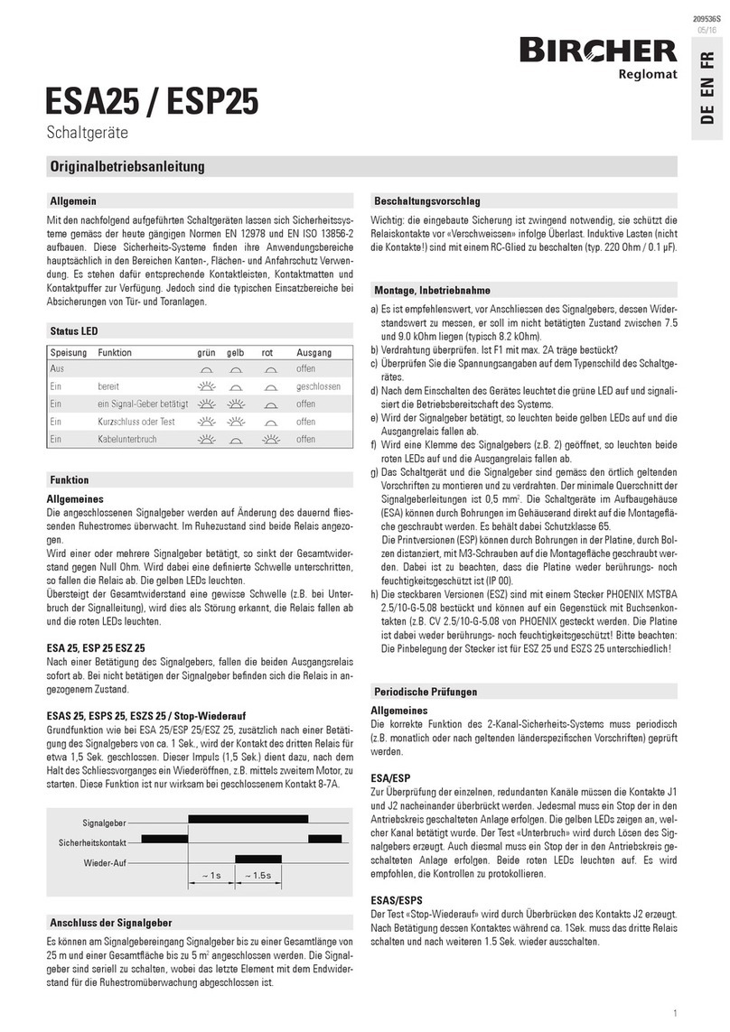
Angeschlossene Signalgeber sind mit einem Endwiderstand von 8,2 kOhm
auf Änderungen des dauernd iessenden Ruhestromes überwacht. Im Ruhe-
zustand sind beide Relais angezogen.
Bei Betätigung eines oder mehrerer Signalgeber
• sinkt der Gesamtwiderstand gegen Null Ohm
• die denierte Schaltgrenze wird unterschritten (ca. 2 kOhm)
• die Relais fallen ab
• die gelbe LED leuchtet
Bei Störung im Signalgeberkreis (Kabelbruch, Signalgeberausfall...)
• der Gesamtwiderstand steigt
• die denierte Schaltgrenze wird überschritten (ca. 9 kOhm)
• die Relais fallen ab
• die rote LED leuchtet
Status LED
Speisung Funktion grün gelb rot Ausgang
Aus offen
Ein bereit geschlossen
Ein ein Signal-Geber betätigt offen
Ein Kurzschluss oder Test offen
Ein Kabelunterbruch offen
Anschluss
• maximale Gesamtlänge des Signalgebers mit Kabel 50 m
• maximale Gesamtäche des Signalgebers 5 m2
• mehrere Signalgeber werden in Serie geschaltet
• der Gesamt-Widerstand darf 8,2 kOhm nicht übersteigen
Wichtig:
– die eingebaute Sicherung ist zwingend notwendig (dient dem
Schutz der Relaiskontakte vor «Verschweissen» bei Überlast)
– induktive Lasten sind mit einem RC-Glied zu beschalten
(220 Ohm/0,1 µF)
– periodisch sind Funktionstests durchzuführen. Es sind die dafür
vorgesehenen Prüfkontakte zu überbrücken (siehe Bestückung)
Bei Missachtung dieser Bedienungsanleitungs-Angaben wird der
Schutz des Gerätes in Frage gestellt. Der Betreiber handelt auf eige-
nes Risiko!
Blockschema
Signal-
geber 1
22(5)
32(8) R1
R3
24(7)
34(9)
A1(2)
A2(10)
Speisung
Signal-
geber 2
oder 8,2kOhm Widerstand
F1
11(1)
Antriebs-
kreis
21(6)
ESR25
• zwei parallele Signalgebereingänge
• ein Sicherheitsausgang
• Speisung 24 VACDC
• redundante Auswertung der Signalgeber
ESR26
• zwei getrennte Signalgebereingänge
• zwei getrennte Sicherheitsausgänge
• Speisung 24 VACDC
• redundante Auswertung beider Kanäle
Signal-
geber 1
22(5)
32(8)
R1
R3
R2
R4
24(7)
34(9)
A1(2)
A2(10)
Speisung
Signal-
geber 2
F1
F2
11(1)
Antriebs-
kreis 1
Antriebs-
Kreis 2
21(6)
14(3)
12(4)

2
Bestückung Technische Daten
Gehäuse NORYL, rot
Front schwarz
Masse 85 x 74 x 36 mm
Schutzart IP30
Schutzart Einsatzort IP54
Temperaturbereich –20°C bis +55°C
Spannungsversorgung 24 VACDC ±10%
Frequenz 50/60 Hz
Leistungsaufnahme ESR25
< 3 VA
ESR 26
< 5 VA
Signalgeber-Eingang
– Ansprechwert «Betätigung»
– Ansprechwert «Unterbruch»
ESR25
< 2,3–2,5 kOhm
> 8,9–10,4 kOhm
ESR 26
< 1,4–1,8 kOhm
> 8,6–9,3 kOhm
Ansprechzeit max. 12 ms
Signalausgabe-Relais 2A/250 VAC pro Kanal
Anzeigen
– Betrieb
– Sicherheitsabschaltung
– Störung (Unterbruch)
LED 3 mm
Grün
Gelb
Rot
Überspannungskategorie II (EN 61010-1)
Verschmutzungsgrad 2 (EN 61010-1)
Schutzklasse 0 (EN 60730-1) und EN 60335-1)
Die Spannungsversorgung muss aus einem Sicherheitstrafo nach IEC 742
erzeugt werden. Die Leitungsverlegung muss geschützt vor mechanischen
Beschädigungen erfolgen.
1. Die Gewährleistung und Haftung der Bircher Reglomat AG richten sich nach dem
Kaufvertrag.
2. Die Gewährleistung und Haftung erlischt vorzeitig, wenn der Kunde oder Dritte das
Produkt nicht gemäss der vorliegenden Betriebsanleitung einsetzen und/oder be-
dienen, der Kunde oder Dritte unsachgemässe Änderungen oder Reparaturen vor-
nehmen, der Kunde oder Dritte, falls ein Mangel aufgetreten ist, nicht umgehend
alle geeigneten Massnahmen zur Schadensminderung treffen und der Bircher Reg-
lomat AG Gelegenheit geben, den Mangel zu beheben.
3. Von der Gewährleistung und Haftung ausgeschlossen sind Schäden, die nicht nach-
weisbar infolge schlechten Materials, fehlerhafter Konstruktion oder mangelhafter
Hersteller: Bircher Reglomat AG, Wiesengasse 20, CH-8222 Beringen
Es wurden folgende Richtlinien eingehalten: MD 2006/42/EG, RoHS 2011/65/EU, EMC 2014/30/EU
Baumusterprüfbescheinigung: In Kombinationen mit Schaltleisten
Notizierte Stelle: Suva, Bereich Technik, SCESp 0008, Kenn-Nr.1246
Produktvarianten: ESR25-24VACDC, ESR26-24VACDC
Identizierung des Baujahrs Kontakt
EU-Konformitätserklärung
Bircher Reglomat AG
Wiesengasse 20
CH-8222 Beringen
www.bircher-reglomat.com
Ausführung entstanden sind sowie Schäden, die aus anderen Gründen entstanden
sind, welche die Bircher Reglomat AG nicht zu vertreten hat.
4. Eine Haftung für Folgeschäden ist ausgeschlossen, soweit zwingende produktehaft-
pichtrechtliche Bestimmungen dem nicht entgegenstehen.
5. Die Gewährleistungsansprüche aus dem Kaufvertrag gegenüber dem Händler wer-
den durch diese Bestimmungen nicht berührt.
6. Bircher Reglomat AG entwickelt ihre Produkte zum Nutzen ihrer Kunden stetig wei-
ter. Bircher Reglomat AG behält sich das Recht vor, ohne vorherige Ankündigung, an
jedem in dieser Dokumentation erwähnten Produkt, Änderungen vorzunehmen.
Gewährleistung und Haftung
Jahr Monat Tag
2015 06 17
Änderungen vorbehalten
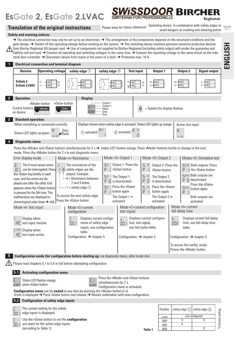
F1
F2
LED
4
3
2
1
6
5
J1
J3
J4
REL1
REL3
REL2
REL4
J2
ESR26
F1
LED
4
3
2
1
5
J1
J4
REL1
REL3
ESR25
LED5 Betriebsanzeige (grün)
LED6 Betriebsanzeige (grün) (nur ESR26)
LED1, LED2 Funktionsanzeige (gelb)
LED3, LED4 Störungsanzeige (rot)
REL1, REL3 Schaltkreis 1, Arbeitskontakte seriegeschaltet
REL2, REL4 Schaltkreis 2, Arbeitskontakte seriegeschaltet (nur ESR26)
F1 Sicherung 2AT Relaiskontaktschutz
F2 Sicherung 2AT Relaiskontaktschutz (nur ESR26)
J1 Prüfkontakt für REL1
J2 Prüfkontakt für REL4 (nur ESR26)
J3 Prüfkontakt für REL2 (nur ESR26)
J4 Prüfkontakt für REL3
Klemmen-/Anschlussbelegung
Klemmen ESR25 ESR26
Al,A2 (2,10) Speisung 24VACDC Speisung 24 VACDC
22,32 (5,8) Signalgeber-Eingang Signalgeber-Eingang 1
24,34 (7,9) Signalgeber-Eingang (oder 8,2kOhm) Signalgeber-Eingang 2
11,21 (1,6) Sicherheits-Ausgang Sicherheits-Ausgang 1
12,14 (3,4) – Sicherheits-Ausgang 2
31 (11) – –

3
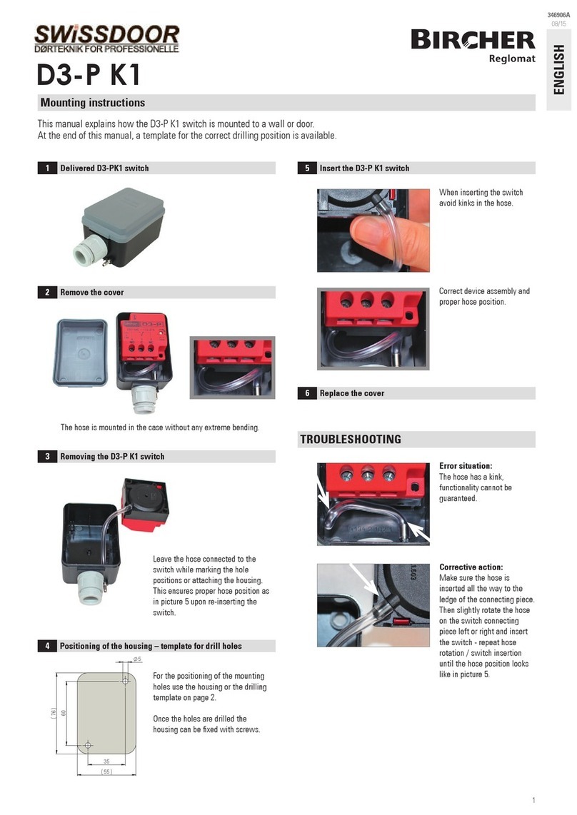
Assembly, Commissioning, Periodical Tests
1. Check the resistance. In the non-activated state between 8.1 kOhm and
8.6 kOhm (typical 8.2 kOhm).
2. Check the wiring. F1 (ESR26: F1 and F2) tted with max. 2 A slow blow?
3. Switch on the unit. When operational the green LED illuminates (with
ESR26 both green LED’s)
4. Activate the signal transmitter. The corresponding yellow LED illuminates
(with ESR26 both yellow LED’s) and the output relay de-energises.
5. The red LED (with ESR26 both red LED’s) illuminates and the output relay
deenergises when a terminal of the signal transmitter is not connected.
Important:
Assembly and wiring according to local regulations. The minimal
cross-sectional area is 0.14 mm2. May only be installed in a IP54
housing.
For periodical testing, the contacts J1 and J4 (with ESR26 J2 and J3) must
be bridged consecutively (see Layout). Each time a Stop must occur. The test
«interruption» is achieved by disconnecting the signal transmitter. Stop must
occur.
We recommend that the tests be documented.
The tests are to be carried out by trained personell using a tool with
insulated handle.
ESR25/26
Switching Units
Operating Instructions
ENGLISH
209491S
06/16
General
The difference between the ESR25 and ESR26 is that the ESR26 has two se-
parate evaluation circuits.
Function
Connected sensors are monitored with a terminating resistance of 8.2 kOhm
to detect changes in the constant owing zero-signal current. Both relays are
energised in the non-active condition.
If one or more sensors are activated
• the total resistance drops towards zero ohm
• when the resistance falls below the dened limit (2 kOhm)
• the relays de-energise
• the yellow LED illuminates
When a fault occurs in the sensor circuit (cable breakage, sensor defect…)
• the total resistance increases
• when the resistance exceeds the dened limit (9 kOhm)
• the relays de-energise
• the red LED illuminates
Status LED
Supply Function green yellow red Output
Off open
On ready closed
On one sensor activated open
On short-circuit or test open
On cable breakage open
Connection
• max. total length of sensor with cable 50 m
• max. total area of sensor 5 m2
• multiple sensors are connected in series
• the total resistance must not exceed 8.2 kOhm
Important:
– The installed fuse is absolutely neccesary. It protects the relay
contacts against «welding» when overloaded.
– Suppressors (220 Ohms/0.1 uF) are to be connected across the in-
ductive loads.
– Periodical function test are to be made.
The designated test contacts are to be bridged (see Layout).
The protection of the unit will be endangered by non-adherence of
these operating manual instructions.
The user acts at his own risk!
Block Diagram
Sensor 1
22(5)
32(8) R1
R3
24(7)
34(9)
A1(2)
A2(10)
Supply
Voltage
Sensor 2
or 8.2kOhm resistance
F1
11(1)
Drive
Circuit
21(6)
ESR25
• two parallel sensor inputs
• safety output
• supply voltage 24 VACDC
• redundant evaluation of the sensor
ESR26
• two separate sensor inputs
• two separate safety outputs
• supply voltage 24 VACDC
• redundant evaluation of both channels
Sensor 1
22(5)
32(8)
R1
R3
R2
R4
24(7)
34(9)
A1(2)
A2(10)
Supply
Voltage
Sensor 2
F1
F2
11(1)
Drive
Circuit 1
Drive
Circuit 2
21(6)
14(3)
12(4)

4
Layout Technical Data
1. The warranty and liability of Bircher Reglomat AG are based on the sales contract.
2. The warranty and liability shall expire prematurely, should the client or third parties
not use and/or operate the product in compliance with existing operating instruc-
tions, should incorrect changes or repairs be made by the client or third parties,
should the client or third parties, when a fault has occurred, not take suitable steps
at once for a reduction of possible damage/losses and offer Bircher Reglomat AG a
chance for remedying the said fault.
3. The warranty and liability shall exclude any damage for which there is no proof that
it is due to poor materials, faulty construction, poor workmanship, and any damage
caused by other reasons, for which Bircher Reglomat AG cannot be held liable.
Manufacturer: Bircher Reglomat AG, Wiesengasse 20, CH-8222 Beringen
Following directives have been observed: MD 2006/42/EC, RoHS 2011/65/EU, EMC 2014/30/EU
EC type-examination certicate: In combination with Safety Edges
Notied inspection centre: Suva, technology division, SCESp 0008, ID no.1246
Product variants: ESR25-24VACDC, ESR26-24VACDC
Identication of the year of manufacture Contact
EC-Declaration of Conformity
Bircher Reglomat AG
Wiesengasse 20
CH-8222 Beringen
www.bircher-reglomat.com
4. No liability can be assumed for any consequential damage, provided this is not
governed otherwise by applicable product liability laws and regulations.
5. Warranty claims made against the seller on the basis of the sales agreement are
not affected by these regulations.
6. For the benet of its customers Bircher Reglomat AG constantly develops its pro-
ducts further. Bircher Reglomat AG reserves the right to make changes to any of the
products described in this document without prior notice.
Warranty and liability
Year Month Day
2015 06 17
Housing NORYL, red
Face Black
Dimensions 85 x 74 x 36 mm
Isolation Class IP30
Isolation Class IP54
Temperature Range –20°C to +55°C
Power Supply 24 VACDC ±10%
Frequency 50/60 Hz
Power Consumption ESR25
< 3VA
ESR26
< 5VA
Sensor Input
– Reaction Value «Activated»
– Reaction Value «Interruption»
ESR25
< 2.3–2.5 kOhm
> 8.9–10.4 kOhm
ESR26
< 1.4–1.8 kOhm
> 8.6–9.3 kOhm
Reaction Time max. 12 ms
Signal Output Relay 2A/250VAC per channel
Display
– Operation
– Safety Switch-off
– Error (Interruption)
LED 3 mm
Green
Yellow
Red
Overvoltage Category II (EN 61010-1)
Contamination Grade 2 (EN 61010-1)
Protection Class 0 (EN 60730-1 and EN 60335-1)
The supply voltage must be obtained from a safety trafo according to IEC742.
The wiring must be protected against mechanical damage.
Rights reserved for technical modications
F1
F2
LED
4
3
2
1
6
5
J1
J3
J4
REL1
REL3
REL2
REL4
J2
ESR26
F1
LED
4
3
2
1
5
J1
J4
REL1
REL3
ESR25
LED5 Operation Display (green)
LED6 Operation Display (green) (only ESR26)
LED1, LED2 Function Display (yellow)
LED3, LED4 Error Display (red)
REL1, REL3 Switching Circuit 1, Working contact switched in series
REL2, REL4 Switching Circuit 2, Working contact switched in series
(only ESR26)
F1 Fuse 2 Amp slow Relay contact protection
F2 Fuse 2 Amp slow Relay contact protection (only ESR26)
J1 Test Contact for REL1
J2 Test Contact for REL4 (only ESR26)
J3 Test Contact for REL2 (only ESR26)
J4 Test Contact for REL3
Terminal/Connections
Terminal ESR25 ESR26
Al,A2 (2,10) Supply 24VACDC Supply 24 VACDC
22,32 (5,8) Sensor-Input Sensor-Input 1
24,34 (7,9) Sensor-Input (or 8.2kOhm) Sensor-Input 2
11,21 (1,6) Safety-Output Safety-Output 1
12,14 (3,4) – Safety-Output 2
31 (11) – –
This manual suits for next models
1
Table of contents
Languages:
Other Bircher Reglomat Switch manuals