BirCraft BADCD12-10 User manual

Address: 320 B Percheron Road, Kyalami, Midrand, 1684
GPS Coordinates: S 25.98115º / E 028.06869º
BirCraft
GEARED MOTORS - LINEAR ACTUATORS - CONTROLS
t:
+ (27) 011 468 1881
c:
+(27) 074 465 1744
e:
01@BirCraft.co.za
w:
www.BirCraft.co.za
GUIDELINE DIMENSIONS ONLY
- Over
40 Years
of Supplying Africa -
Variable DC Speed Drives –Operation Manual
BADCD12-10 and BADCD24-10
Contents
Safety Precautions: .............................................................................................................................................................................................................................. 1
Specification and Model: ..................................................................................................................................................................................................................... 1
Product Characteristics:....................................................................................................................................................................................................................... 2
Installation Requirements:................................................................................................................................................................................................................... 2
Performance Indexes:.......................................................................................................................................................................................................................... 2
Wiring Requirements:.......................................................................................................................................................................................................................... 3
Driver Terminal Function Diagram:...................................................................................................................................................................................................... 3
Description of control Terminal’s Functions: ....................................................................................................................................................................................... 3
EN (Enable Control).................................................................................................................................................................................................................... 3
DIR (Direction Control)............................................................................................................................................................................................................... 3
C E (OC Door Alarm Output)....................................................................................................................................................................................................... 4
4. S1 S2 S3 Signal Output Terminal: ..................................................................................................................................................................................................... 4
Description of Indicator: ...................................................................................................................................................................................................................... 5
Regulation Description of Functional Potentiometer:.......................................................................................................................................................................... 5
Driver Examination steps before Charged: .......................................................................................................................................................................................... 5
Common Fault Treatment:................................................................................................................................................................................................................... 5
Safety Precautions:
•Installation, connection and commissioning of this device shall be carried out by professionals.
•Do not install, remove or replace device circuit under charged circumstances.
•Please make sure that necessary protectors are mounted between power input end of this device and power supply
(storage battery) to avoid accidents or fatal damages; Devices need to be mounted: over-current protector, fuse,
emergency switch.
•Isolation and insulation protection between device and ground as well as devices shall be well equipped.
•In case that charged commissioning of this device is really needed, well-insulated non-metal special screwdriver or
special commissioning tools shall be used.
•This device shall be installed in well-ventilated environment.
•This device shall not be directly exposed to abnormal environments with high humidity, dust, corrosive gas and intense
vibration.
Specification and Model:
PRODUCT #:
CONTINUOUS OUTPUT CURRENT
DC (A):
MAX OUTPUT CURRENT
DC (A):
DC VOLTAGE WORKING RANGE
10-18 DC (V):
BADCD12-10
10
20
10 - 18
BADCD24-10
10
20
20 - 55

T: 011 468 1881 |www.BirCraft.co.za
C: 074 465 1744 |e: 01@BirCraft.co.za
Address: 320 B Percheron Road, Kyalami, Midrand, 1684
GPS Coordinates: S 25.98115º / E 028.06869º
Page 2of 5
Variable Speed Drives –Operation Manual
BADCD12-10 and BADCD24-10
- Over
40 Years
of Supplying Africa -
GUIDELINE DIMENSIONS ONLY
Product Characteristics:
This series of speed controller is a low voltage DC four-quadrant regeneration pulse width controller adopts special single-chip
intelligent control system and has rapid response speed, steady operation, reliable work status and multiple protection functions.
•SMT technology, small size.
•Pulse width modulation.
•Low noise during operation, high efficiency, and low maintenance cost which better enhance the service life of DC
motor.
•Four-quadrant regenerative operating mode.
•Regenerative braking function.
•It doesn’t need external reversing contactor and will not result in electric motor parts or other components overheating
or burning down.
•Enable/ reversing terminal.
•To realize certain functions by using simple passive switching value or transistor collector open circuit.
•Status indicator light - Power supply indicator and over-current alarm indicator can provide the visible status of speed
controller.
•Output current setting function (amplitude limiting).
•Torque compensate function.
•Double closed-loop PI regulation (current, voltage).
•Standard analogue quantity signal control analogue quantity: 0-6V 0-10V or controlled by potentiometer
•A broader scope of input voltage: 10-55V.
Installation Requirements:
•Controller cannot be installed, connected or removed under charged circumstance. Otherwise accidents or severe
damages may be caused. Users should read and understand the details of “safety warning” (Page 1) before installation
and obey the rules strictly.
•Drive element is sensitive to electrostatic magnetic interference shall be kept away from environments where static is
easy to be generated; otherwise, speed controller may be damaged.
•The driver shall be kept away from dust, high humidity environment and prevented from accidental contact. Enough
space shall be reserved around the driver for easy ventilation and regulation.
•When fixed, the driver shall be kept from other heat sources. Guarantee that the driver works in the specified
environment temperature range.
•The driver shall not be installed on equipment’s with extreme vibration; if not, precaution against vibration shall be
taken.
Performance Indexes:
SPEED RATIO:
1:100
CONTROL POTENTIOMETER
(1K ……50K) / 2W
INPUT VOLTAGE:
10-55V VDC
OUTPUT CURRENT:
0-20A (Amplitude Limiting)
INPUT IMPEDANCE:
≥50KΩ
ROTATE SPEED (STANDARD PRECISION %):
1 %
START/BRAKING TIME:
0.2-20 S
ENVIRONMENT TEMPERATURE:
-10°C + 50°C
ENVIRONMENT HUMIDITY:
≤80RH (no moisture condensation) (relative humidity)
INSULATION AND VOLTAGE RESISTANCE:
1100V DC 1 minute
INSULATION RESISTANCE:
> 20 MΩ
LEAKAGE CURRENT:
≤ 0.9 mA
WEIGHT:
0.25 KG
•It is appropriate for permanent magnet and separately excited motor
T: 011 468 1881 |www.BirCraft.co.za
C: 074 465 1744 |e: 01@BirCraft.co.za
Address: 320 B Percheron Road, Kyalami, Midrand, 1684
GPS Coordinates: S 25.98115º / E 028.06869º
Page 3of 5
Variable Speed Drives –Operation Manual
BADCD12-10 and BADCD24-10
- Over
40 Years
of Supplying Africa -
GUIDELINE DIMENSIONS ONLY
Wiring Requirements:
•Do not connect wire under charged.
•Insulated connection, shielded wire which match with driver’s voltage current shall be selected and connected,
specifications of driver’s power input wire and motor’s wire are shown below:
Table 1 Wire Specification and Length Table
CURRENT (A)
WIRE SPECIFICATION (MM2)
MAX. LENGTH (M)
10
1.5
15
20
2.5
15
•Signal line and control line shall adopt shielded wire and shall be separated with power input wire and output wire.
•The driver does not have internal power supply reverse connection protection function, make sure that wiring between
power input and driver is correct, otherwise the driver may be damaged.
•Proper tools shall be used for wiring and make sure that wiring is correct.
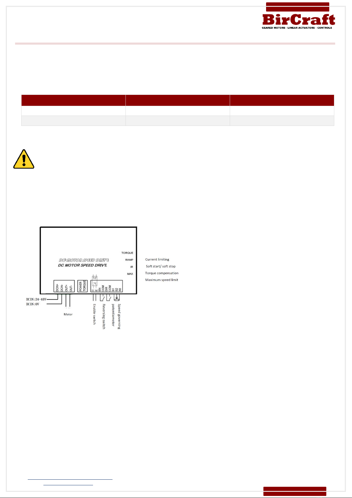
Driver Terminal Function Diagram:
Description of control Terminal’s Functions:
EN (Enable Control)
During motor operation, simply connect/ disconnect EN with COM to control the start and stop of motor
Connect EN terminal with COM, EN terminal is effective, at this time regulate external speed potentiometer and
motor is in normal operation.
EN terminal suspends in the air or is not connected, EN terminal is invalid; circuit of controller is blocked and motor
stops.
DIR (Direction Control)
During motor operation, simply connect/ disconnect EN with COM to reverse the motor rotation. It doesn’t need
external reversing contactor and will not result in electric motor parts or other components overheating or burning
down.
Connect DIR terminal with COM, DIR terminal is effective, motor is in negative rotation.
DIR terminal suspends in the air or is not connected, DIR terminal is invalid; motor is in positive rotation (runs in
opposite direction as above mentioned).
In any cases, signal line and logic control line shall not be bound, mixed and wired with power input wire, output wire
(motor line) and other power lines. Induced voltage generated may cause interface, malfunction or directly damage the
driver.
T: 011 468 1881 |www.BirCraft.co.za
C: 074 465 1744 |e: 01@BirCraft.co.za
Address: 320 B Percheron Road, Kyalami, Midrand, 1684
GPS Coordinates: S 25.98115º / E 028.06869º
Page 4of 5
Variable Speed Drives –Operation Manual
BADCD12-10 and BADCD24-10
- Over
40 Years
of Supplying Africa -
GUIDELINE DIMENSIONS ONLY
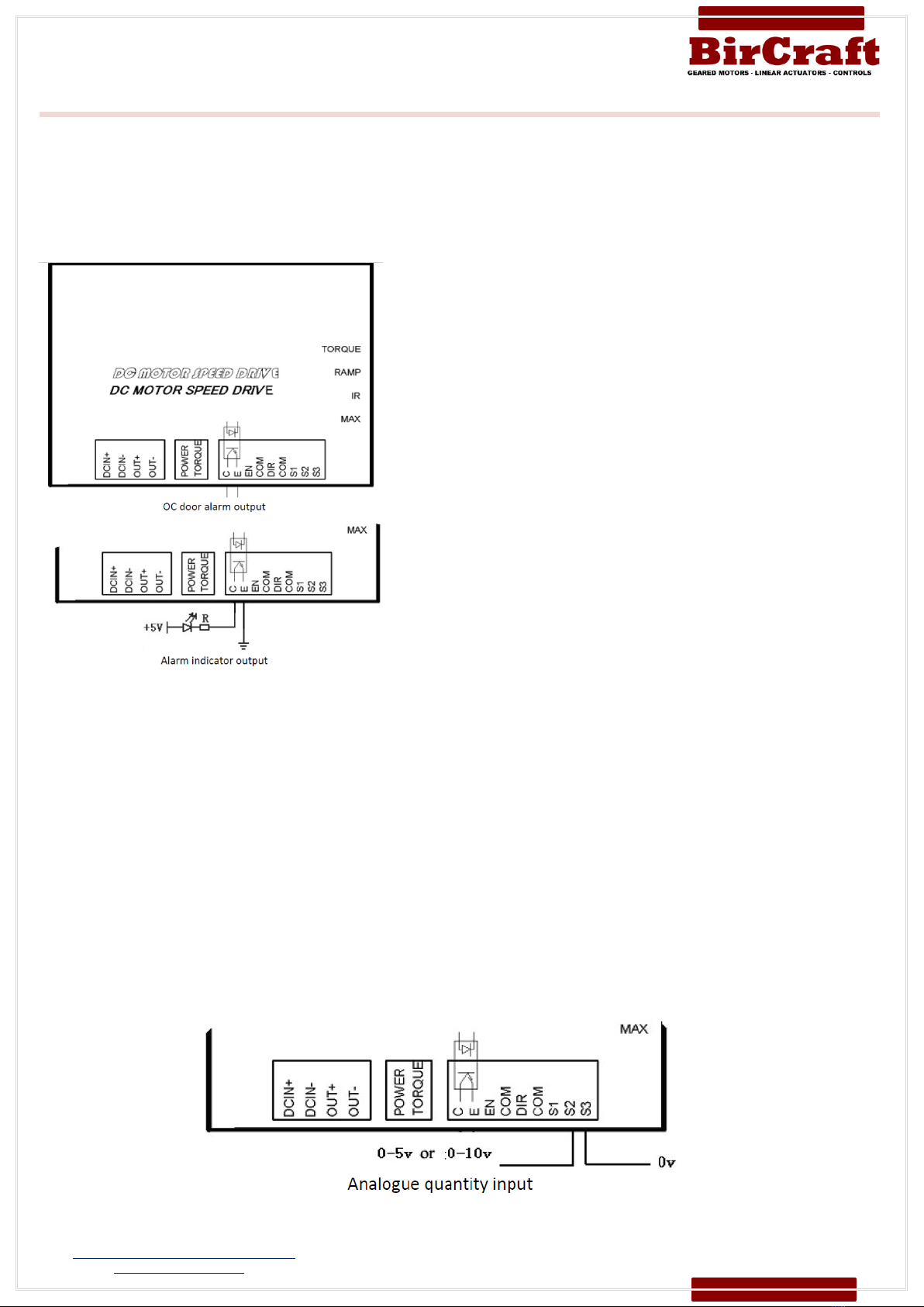
C E (OC Door Alarm Output)
The internal design of “OC door alarm output”is that over‐current signal is transmitted through an opto‐coupler to
give alarms. When over‐current is detected on the controller, over‐current signal will be immediately sent to diode
of opto‐coupler for break over and then transmitted to C, E ports. The client can wire as their own requirements, as
shown in Figure 1, connect to over‐current indicator, Figure 2, relay actuation after over‐current to give alarms.
Internal wiring diagram of “OC door alarm output”is shown as follows:
4. S1 S2 S3 Signal Output Terminal:
Such controller has two control modes of external speed potentiometer control and external analogue quantity input.
Description of various terminals is as follows:
•S1 Terminal: external power+10V ,
•S2 Terminal: signal input terminal
•S3 Terminal: GND (grounded).
When external speed potentiometer control is used, S1, S2, S3 terminals shall be connected with external potentiometer as
shown in VI. Driver terminal function diagram to regulate external potentiometer for speed governing
When external analogue quantity input control is used, speed can be controlled through S2 and S3 input, both 0‐ 5V and 0‐10V
are OK.

T: 011 468 1881 |www.BirCraft.co.za
C: 074 465 1744 |e: 01@BirCraft.co.za
Address: 320 B Percheron Road, Kyalami, Midrand, 1684
GPS Coordinates: S 25.98115º / E 028.06869º
Page 5of 5
Variable Speed Drives –Operation Manual
BADCD12-10 and BADCD24-10
- Over
40 Years
of Supplying Africa -
GUIDELINE DIMENSIONS ONLY
Description of Indicator:
POWER (Green) power indicator:
If the controller is charged, this indicator lights up to indicate that controller is under normal operation.
TORQUE (Red) over-current indicator:
Turns red to indicate that output current of the controller exceeds client’s pre-set current, and the controller will automatically
limit the output current to such value.
Regulation Description of Functional Potentiometer:
MAX (Maximum Revolving Speed Limit)
It is used for limiting motor’s maximum revolving speed. Increase in clockwise rotation and decrease in counter clockwise rotation.
IR (Torque Compensation)
Regulate “IR” enable motor work under different loads and keep revolving speed constant (normally factory default is 0), Increase
in clockwise rotation and decrease in counter clockwise rotation.
RAMP (Soft Start/ Stop)
Regulate “RAMP” to set motor’s starting and stopping time (1-20 S). Increase in clockwise rotation.
TORQUE (Current Limit Regulation)
Regulate “TORQUE” to set over-current protection value of the controller; regulating range is 0-20A, Increase in clockwise rotation
and decrease in counter clockwise rotation. When reaches over-current limit value, over-current indicator (Red) lights constantly
and current is be limited to such value, at this time, continue to regulate the external potentiometer, current value is invariant(
i.e. amplitude limiting).
Driver Examination steps before Charged:
•Firstly, check whether positive and negative connection of battery pack and driver is correct, reliable and whether input
power is within driver’s applicable range.
•Check whether the circuit board of driver is clean, clear and without conductive metals, humidity, dew and debris
•Check whether periphery connecting line of driver is correct and free from short circuit and ground connection.
•Confirm that external speed governing potentiometer is at minimum position (given signal is at 0)
Common Fault Treatment:
PROBLEMS
CAUSES
RECOMMENDED SOLUTIONS
Motor is out-of-
operation
1. Wiring is incorrect.
2. Command signal is0V.
3. Disconnection of INHIBIT enable
terminal.
4. Current output is limited.
1. Carefully check the wiring between controller and motor
2. Regulate external potentiometer or external analogue signal
3. Contact enable terminal
4. Regulate the output current of controller after confirming that
motor is not blocked
Acceleration and
deceleration time of
motor is improper
Regulate of starting and breaking
potentiometer is inappropriate
Regulate starting and breaking potentiometer
Motor vibrates after
acting load
1. IR COMP setting is too big
2. Lack of current limit
1. Carefully regulate the setting of IR COMP
2. Regulate the TORQUE potentiometer after confirming that motor
matches well with the driver
Speed up after acting
load of motor
IR COMP setting is too small
Increase IR COMP setting
Slow down after
acting load of motor
IR COMP setting is too big
Decrease IR COMP setting
This manual suits for next models
1
Table of contents
Popular DC Drive manuals by other brands


WEG
WEG CFW-11 Series Programming manual

lumishore
lumishore SUPRA SY225 Installation and operating instructions

Danfoss
Danfoss VLT HVAC FC 100 Service manual

GG
GG Emotron DSV35 Mounting and switch on instruction

GFA
GFA ELEKTROMAT SIK 25.10 WS-30,00 installation instructions

Vacon
Vacon 100 INDUSTRIAL Applications manual