Eurotherm 590SP User manual

590SP Digital
DC Drive
Product Manual
Version 1 Firmware
© Copyright Eurotherm Drives, Inc. 1995
All rights strictly reserved. No part of this document may be stored in a retrieval system or transmitted in any form.
Although every effort has been taken to ensure the accuracy of this manual, it may be necessary, without notice, to make amendments or correct omissions in this document. Eurotherm Drives, Inc.
cannot accept responsibility for damage, injury, or expenses resulting therefrom.
Procedures detailed in this manual are designed to be performed by personnel with sufficient training and/or experience. Only sufficiently qualified personnel familiar with the construction and
operation of industrial drive equipment and the dangers of working with high-voltage electrical systems should attempt installation, adjustment, operation, or service of this equipment. Failure to
follow these guidelines could result in damage to the equipment and severe injury or loss of life to personnel. If you are unsure of your qualifications or do not understand certain procedures in this
manual, contact Eurotherm Drives Customer Service for assistance. Before attempting any procedures in this manual, including installation, verify that the model numbers on the product and in this
manual match. If any discrepancy is found, contact Customer Service immediately.
Procedures in this manual may contain Warnings, Cautions, and Notes. A Warning gives the reader information which, if disregarded, could cause injury or death. A Caution provides the reader with
advice which, if disregarded, could cause damage to the equipment. A Note furnishes additional information for added emphasis or clarity.
Printed in the United States of America HA353002 Issue 1


Safety Warnings
Safety
Procedures in this manual may contain Warnings, Cautions, and Notes. A Warning gives the reader information
which, if disregarded, could cause injury or death. A Caution provides the reader with advice which, if disregarded,
could cause damage to the equipment. A Note furnishes additional information for added emphasis or clarity.
The customer is responsible for assessing his or her ability to carry out the procedures in this manual. Make sure you
understand a procedure and the precautions necessary to carry it out safely before beginning. If you are unsure of your
ability to perform a function, or have questions about the procedures listed in this manual, contact Eurotherm Drives
Customer Service at (704) 588-3246.
WARNING!
Only qualified personnel who thoroughly understand the operation of this equipment and any associated
machinery should install, start-up, or attempt maintenance of this equipment.
WARNING!
This equipment uses hazardous voltages during operation. Never work on it or any other control
equipment or motors without first removing all power supplies.
Caution
This equipment contains ESD (Electrostatic Discharge) sensitive parts. Observe static control
precautions when handling, installing, and servicing this device.
Caution
This equipment was tested before it left our factory. However, before installation and start up, inspect all
equipment for transit damage, loose parts, packing materials, etc.
Caution
Ruptured semiconductor devices may release toxic materials. Contact Eurotherm Drives or the
semiconductor manufacturer for proper disposal procedures for semiconductors or other material.
NOTE. The installation of this equipment must comply with all applicable national and local electrical codes.
Warn. 1 590SP Digital Product Manual

Terms & Conditions
EUROTHERM DRIVES INCORPORATED - TERMS AND CONDITIONS (ABRIDGED)
The following text will in no way alter or void the contents of the Eurotherm Drives, Inc. - Terms and Conditions of
Sale. It is only intended to clarify the responsibilities of each party.
Delivery, Title and Risk
. . . DELIVERY TO COMMON CARRIER OR POSTAL AUTHORITIES AT RESTON, VIRGINIA SHALL CONSTITUTE DELIVERY
AND PASSING OF TITLE TO THE CUSTOMER, WHO SHALL THEREAFTER BE RESPONSIBLE FOR DELAYS, LOSS OR
DAMAGE IN TRANSIT.
Warranty and Liability
A. Warranty of equipment found within 12 months after delivery thereof to be defective by reason of faulty materials, workmanship, or
design.
(i) The Customer will:
(a) notify Eurotherm Drives, Inc. within four weeks of the defect becoming apparent
(b) return the equipment forthwith, freight paid, to the premises of Eurotherm Drives, Inc. or
(c) at the option of Eurotherm Drives, Inc. make the equipment available at the Customer’s premises for attention by Eurotherm
Drives, Inc. personnel. Where the equipment is repaired on the Customer’s premises, the Customer accepts liability for the
payment of travel and subsistence expenses of Eurotherm Drives, Inc. personnel.
(ii) Eurotherm Drives, Inc. will:
(a) repair or (at its option) replace any equipment manufactured by Eurotherm Drives, Inc.
(b) for goods not manufactured by Eurotherm Drives, Inc., convey to the Customer only the benefits it may recover under any
guarantee the manufacturer gives to Eurotherm Drives, Inc.
B. Eurotherm Drives, Inc. accepts no liability under this clause:
(i) for damage sustained in transit, (liability for which is dealt with in paragraph 8 hereof);
(ii) for defects caused
(a) by not following the instructions supplied with the equipment during installation, operation or maintenance or
(b) by wear and tear, accident or misuse, improper operation or neglect or
(c) by fitting any equipment which does not comply with Eurotherm Drives, Inc. recommendations or
(d) otherwise as a result of failure of the Customer to comply in full with any manual or handbook containing the technical
specifications and operating instructions supplied by Eurotherm Drives, Inc. with the equipment;
(iii) where equipment has been used for an application other than that specified at the time the Order was acknowledged or not in
accordance with Eurotherm Drives, Inc. instructions;
(iv) where the Customer has failed to observe the terms of payment for the equipment and all other obligations imposed by these terms
and conditions.
C. Where equipment has been ordered, obtained or manufactured to the Customer’s own design or specification, Eurotherm Drives, Inc. can
accept no liability for any failure or defect in such equipment except insofar as such failure or defect arises directly as a result of the
failure of Eurotherm Drives, Inc. to follow the design or specification provided.
Eurotherm Drives, Inc. gives no warranty as to the fitness for any particular purpose of goods supplied to the Customer’s design or
specification.
The Customer shall indemnify Eurotherm Drives, Inc. in respect of all liability, loss or damage suffered by Eurotherm Drives, Inc. as a
result of Eurotherm Drives, Inc. following designs or specifications provided by the Customer including any such liability suffered as a
result of a claim by a third party for infringement of intellectual property rights.
D. Except as specifically set out herein, Eurotherm Drives, Inc. shall be under no liability in respect of the quality, conditions or description
of equipment or for any loss or damage howsoever caused to the Customer or to any other person and any term, condition or representa-
tion to the contrary whether express or implied by statute, common law or otherwise is hereby expressly excluded.
E. NO IMPLIED STATUTORY WARRANTY OR MERCHANTABILITY OR FITNESS FOR A PARTICULAR PURPOSE SHALL
APPLY.
Warn. 2590SP Digital Product Manual

Contents (Continued)
Cont. 1
590SP DIGITAL PRODUCT MANUAL
590SP Digtial Product Manual
Safety
Eurotherm Drives Incorporated - Terms and Conditions (abridged)
Chapter 1 INTRODUCTION
Scope.................................................................................................................................................................................................................................... 1 - 1
Overview of the 590SP Digital Drive ......................................................................................................................................................... 1 - 1
Main Features......................................................................................................................................................................................................... 1 - 1
Other Features....................................................................................................................................................................................................... 1 - 2
Handling and Storage .............................................................................................................................................................................................. 1 - 3
Chapter 2 IDENTIFICATION
Basic Part Identification ....................................................................................................................................................................................... 2 - 1
Labeling............................................................................................................................................................................................................................. 2 - 1
Chapter 3 INSTALLATION AND WIRING
Recommended Tools ................................................................................................................................................................................................ 3 - 1
Ventilation and Cooling Requirements ....................................................................................................................................................... 3 - 1
Mounting Instructions .............................................................................................................................................................................................. 3 - 1
Wiring Procedures .................................................................................................................................................................................................... 3 - 3
Wiring Instructions ............................................................................................................................................................................................ 3 - 3
Terminal Torque Ratings ............................................................................................................................................................................... 3 - 3
Wire Ampacity and Supply Rating....................................................................................................................................................... 3 - 4
Main Supply and Armature Connections .........................................................................................................................................3 - 4
Field Supply Connections ............................................................................................................................................................................ 3 - 4
Control Power Wiring.................................................................................................................................................................................... 3 - 4
Motor Isolation ....................................................................................................................................................................................................3 - 6
AC Contactor Wiring.............................................................................................................................................................................3 - 6
DC Contactor Wiring .............................................................................................................................................................................3 - 6
Dynamic Braking.........................................................................................................................................................................................3 - 6
Drive Start Relay ........................................................................................................................................................................................ 3 - 7
Signal Wiring ........................................................................................................................................................................................................ 3 - 7
Enable ................................................................................................................................................................................................................. 3 - 7
Thermistor........................................................................................................................................................................................................ 3 - 7
Program And Coast Stop ..................................................................................................................................................................... 3 - 7
Current Limit ................................................................................................................................................................................................... 3 - 8
Speed Demand............................................................................................................................................................................................. 3 - 8
Start/Stop Input ......................................................................................................................................................................................... 3 - 8
Jog Input............................................................................................................................................................................................................ 3 - 8
Armature Current Feedback Terminal ........................................................................................................................................ 3 - 8
Speed Feedback ................................................................................................................................................................................................. 3 - 8
Analog Tachometer Generators....................................................................................................................................................3 - 9
Wire-ended Electrical Encoders .................................................................................................................................................... 3 - 9
Feedback Receiver Card Installation.......................................................................................................................................... 3 - 9
Microtachs ...................................................................................................................................................................................................... 3 - 10

Contents (Continued)
590SP Digtial Product ManualCont. 2
590SP DIGITAL PRODUCT MANUAL
Chapter 3 INSTALLATION AND WIRING (Continued)
Calibration ...................................................................................................................................................................................................................... 3 - 10
Armature Voltage Calibration .................................................................................................................................................................3 - 11
Armature Current Calibration ..................................................................................................................................................................3 - 11
Speed Feedback Calibration .................................................................................................................................................................... 3 - 11
Final Inspections .......................................................................................................................................................................................................... 3 - 12
Chapter 4 START UP AND ADJUSTMENT
Recommended Tools ............................................................................................................................................................................................... 4 - 1
Check Motor ................................................................................................................................................................................................................. 4 - 1
Check Supply ................................................................................................................................................................................................................ 4 - 2
Initial Drive Start ........................................................................................................................................................................................................ 4 - 3
Adjust Current Loop (AUTOTUNE) ............................................................................................................................................................... 4 - 3
Armature Current Waveform Check .................................................................................................................................................. 4 - 4
Motor Rotation Check ........................................................................................................................................................................................... 4 - 5
Speed Feedback Calibration ........................................................................................................................................................................... 4 - 6
Adjust Speed Loop ................................................................................................................................................................................................... 4 - 7
Other Parameters ...................................................................................................................................................................................................... 4 - 8
Recording Parameters............................................................................................................................................................................................ 4 - 8
Password Protection ............................................................................................................................................................................................... 4 - 9
Entering a Password ....................................................................................................................................................................................... 4 - 9
Changing a Password .................................................................................................................................................................................... 4 - 9
4-Button Reset...................................................................................................................................................................................................... 4 - 9
Chapter 5 TROUBLESHOOTING
Initial Troubleshooting Procedure................................................................................................................................................................. 5 - 1
Recommended Tools....................................................................................................................................................................................... 5 - 2
Status LED Troubleshooting ............................................................................................................................................................................... 5 - 2
LED Functions ........................................................................................................................................................................................................ 5 - 2
Health, Alarm Messages and the Trip Reset.......................................................................................................................................... 5 - 4
Symbolic Error Messages ................................................................................................................................................................................... 5 - 10
Alarm Process .............................................................................................................................................................................................................. 5 - 10
Alarm Status .......................................................................................................................................................................................................... 5 - 10
Drive Diagnostics ...................................................................................................................................................................................................... 5 - 12
Hardware Troubleshooting ............................................................................................................................................................................... 5 - 14
Control Power Missing ................................................................................................................................................................................. 5 - 14
Field Fail Procedure ......................................................................................................................................................................................... 5 - 15
Contractor Failed Procedure .................................................................................................................................................................... 5 - 16
AC Contactor .............................................................................................................................................................................................. 5 - 16
DC Contactor (DRV Models) ............................................................................................................................................................ 5 - 16
SCR Troubleshooting...................................................................................................................................................................................... 5 - 17
Motor Checks ............................................................................................................................................................................................................... 5 - 18

Contents (Continued)
Cont. 3
590SP DIGITAL PRODUCT MANUAL
590SP Digtial Product Manual
Chapter 5 TROUBLESHOOTING (Continued)
Configuration Errors and General Troubleshooting ....................................................................................................................... 5 - 18
Common Performance Problems ........................................................................................................................................................... 5 - 18
Parameter Toggles Between Two Conditions .................................................................................................................... 5 - 18
No SPEED DEMAND ............................................................................................................................................................................... 5 - 18
SPEED SETPOINT has an Unwanted Offset .......................................................................................................................... 5 - 18
Signal Does Not Get Through the RAMP ................................................................................................................................ 5 - 19
Test Points ....................................................................................................................................................................................................................... 5 - 19
Contacting Customer Service .......................................................................................................................................................................... 5 -20
Chapter 6 SERVICE AND MAINTENANCE
Warranty Information ........................................................................................................................................................................................... 6 - 1
Required Tools and Equipment ........................................................................................................................................................................ 6 - 1
Preventive Maintenance ...................................................................................................................................................................................... 6 - 1
Maintenance Procedure ............................................................................................................................................................................... 6 - 1
Controller Assembly Description .................................................................................................................................................................. 6 - 2
Removing the Drive from its Mount .............................................................................................................................................................. 6 - 3
Part Replacement ....................................................................................................................................................................................................... 6 - 3
Replacing the Control Board .................................................................................................................................................................... 6 - 3
Replacing the Power Board ....................................................................................................................................................................... 6 - 3
Replacing Thyristors ....................................................................................................................................................................................... 6 - 3
Appendix A TECHNICAL DESCRIPTION
Control Circuits .............................................................................................................................................................................................. App. A - 1
Power Circuits ................................................................................................................................................................................................ App. A - 1
Overview of Features ............................................................................................................................................................................... App. A - 1
Specifications ................................................................................................................................................................................................. App. A - 2
Storage and Operating Environment .................................................................................................................................... App. A - 2
Electrical Ratings .................................................................................................................................................................................. App. A - 3
DC Supply Loading ...................................................................................................................................................................................... App. A - 3
Controller Output Ratings.............................................................................................................................................................. App. A - 4
Terminal Ratings .................................................................................................................................................................................... App. A - 4
Dimensions ................................................................................................................................................................................................ App. A - 4
Auxiliary Control Jumpers ............................................................................................................................................................ App. A - 5
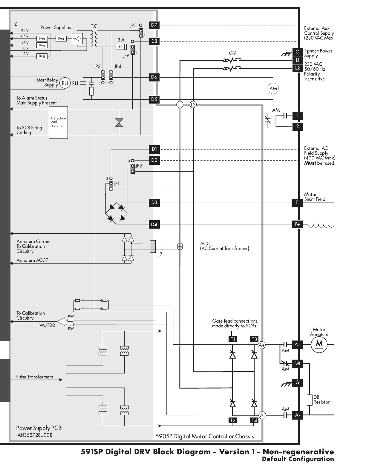
Hardware Block Diagram ...................................................................................................................................................................... App. A - 5
590SP Software Block Diagram ...................................................................................................................................................... App. A - 5
RS422 Communications .......................................................................................................................................................................... App. A - 5
RS232 Communications .......................................................................................................................................................................... App. A - 5
Terminal Listing............................................................................................................................................................................................... App. A - 6
Terminal Specifications ........................................................................................................................................................................... App. A - 7
Analog Input and Output Terminals........................................................................................................................................ App. A - 7
Digital Input Terminals ...................................................................................................................................................................... App. A - 7
Digital Output Terminals ................................................................................................................................................................ App. A - 7
Terminal Descriptions ............................................................................................................................................................................... App. A - 8

Contents (Continued)
590SP Digtial Product ManualCont. 4
590SP DIGITAL PRODUCT MANUAL
Appendix A TECHNICAL DESCRIPTION (Continued)
Feedback Option Cards.......................................................................................................................................................................... App. A - 11
Switchable Tachometer Feedback card (AH385870U001) ............................................................................... App. A - 11
5701 (plastic fiber optic) Microtach Receiver Card (AH058654U001) ................................................... App. A - 12
5701 Installation Information ...................................................................................................................................................... App. A - 13
5901 (Glass) Microtach Receiver Card (AH386025U001) ................................................................................. App. A - 14
Electrical Encoder Receiver Card (AH387775Uxxx) .............................................................................................. App. A - 16
Appendix B USING THE MAN MACHINE INTERFACE
Definition & Scope ....................................................................................................................................................................................... App. B - 1
Using the MMI .................................................................................................................................................................................................. App. B - 1
Software Overview.................................................................................................................................................................................... App. B - 1
MMI Menu Structure ............................................................................................................................................................................ App. B - 1
Default Settings ...................................................................................................................................................................................... App. B - 2
Appendix C SETUP PARAMETERS
RAMPS .................................................................................................................................................................................................................. App. C - 2
AUX I/O .............................................................................................................................................................................................................. App. C - 6
JOG/SLACK ................................................................................................................................................................................................... App. C - 8
RAISE/LOWER ............................................................................................................................................................................................... App. C - 10
CURRENT PROFILE........................................................................................................................................................................................ App. C - 12
STOP RATES..................................................................................................................................................................................................... App. C - 14
SETPOINT SUM 1 .......................................................................................................................................................................................... App. C -20
STANDSTILL...................................................................................................................................................................................................... App. C -22
SPEED LOOP..................................................................................................................................................................................................... App. C -24
SPEED LOOP::ADVANCED ................................................................................................................................................................... App. C -26
SPEED LOOP::SETPOINTS ..................................................................................................................................................................... App. C -28
CURRENT LOOP ............................................................................................................................................................................................ App. C -30
INHIBIT ALARMS ........................................................................................................................................................................................... App. C -32
CALIBRATION ................................................................................................................................................................................................ App. C -34
Appendix D I/O CONFIGURATION - SYSTEM MENU
INTRODUCTION .......................................................................................................................................................................................... App. D - 1
MMI Access to CONFIGURE I/O ........................................................................................................................................... App. D - 1
Parameter types .................................................................................................................................................................................... App. D - 1
Configuration procedure ............................................................................................................................................................... App. D - 2
ANALOG INPUTS ........................................................................................................................................................................................ App. D - 3
Analog Inputs - Examples ............................................................................................................................................................... App. D - 5
ANALOG OUTPUTS .................................................................................................................................................................................. App. D - 7
Analog Outputs - Examples.......................................................................................................................................................... App. D - 9
DIGITAL INPUTS ............................................................................................................................................................................................ App. D - 11
Digital Inputs - Examples ................................................................................................................................................................. App. D - 13
DIGITAL OUTPUTS ...................................................................................................................................................................................... App. D - 15
Digital Outputs - Examples ........................................................................................................................................................... App. D - 17
CONFIGURE 5703 ..................................................................................................................................................................................... App. D - 18

Contents (Continued)
Cont. 5
590SP DIGITAL PRODUCT MANUAL
590SP Digtial Product Manual
Appendix D I/O CONFIGURATION - SYSTEM MENU (Continued)
BLOCK DIAGRAM ....................................................................................................................................................................................... App. D - 19
INTERNAL LINKS ........................................................................................................................................................................................... App. D - 21
Internal Links - Example .................................................................................................................................................................... App. D -23
Appendix E MMI PARAMETER LIST
Appendix F SPARE PARTS LISTS
Ordering Spare Parts ................................................................................................................................................................................ App. D - 1
Reading the Spare Parts Lists ............................................................................................................................................................... App. D - 1
Appendix G RS232 SYSTEM PORT (P3)
SERIAL LINKS::SYSTEM PORT (P3)::P3 SETUP ........................................................................................................................... App. E - 1
Parameters ......................................................................................................................................................................................... App. E - 1
5703 SUPPORT .............................................................................................................................................................................. App. E - 1
BISYNCH SUPPORT .................................................................................................................................................................... App. E - 1
UDP (Upload-Download Protocol) Support ............................................................................................................................... App. E - 2
UDP Menu Parameter Settings ..................................................................................................................................................... App. E - 2
Communication Port Setup............................................................................................................................................................. App. E - 2
Download MMI (DUMP MMI -> P3) ......................................................................................................................................... App. E - 2
UDP Download (UDP XFER -> P3) ............................................................................................................................................... App. E - 3
UDP Upload (UDP XFER <- P3) ....................................................................................................................................................... App. E - 4
Serial Link Port P3 Lead ..................................................................................................................................................................... App. E - 4
5703 (Peer-to-Peer Communications Option) Support .................................................................................................... App. E - 4
Hardware Description ...................................................................................................................................................................... App. E - 5
Appendix H RS422 COMMUNICATIONS (PORTS P1 & P2)
SERIAL LINKS::MAIN PORT (P1) ............................................................................................................................................................App. F - 2
SERIAL LINKS::AUX PORT (P2)...............................................................................................................................................................App. F - 3
SERIAL LINKS::PNO CONFIG................................................................................................................................................................App. F - 4
Communications Standard ......................................................................................................................................................................App. F - 6
ASCII (American Standard Code for Information Interchange) ..................................................................................App. F - 6
Binary Communications .............................................................................................................................................................................App. F - 13
New Serial Link Features ..........................................................................................................................................................................App. F - 15
Serial Link Mnemonics & Parameter Number Allocation .................................................................................................App. F -22
Application Notes .........................................................................................................................................................................................App. F -24
Appendix I PARAMETER LIST BY TAG NUMBER
Appendix J PARAMETER LIST BY MENU
Appendix K PARAMETER LIST BY PARAMETER NAME

Contents (Continued)
590SP Digtial Product ManualCont. 6
590SP DIGITAL PRODUCT MANUAL
Appendix L 590SP DIGITAL DRV OPTION
Description of the 590SP DRV ............................................................................................................................................................. App. L - 1
DRV Mounting Instructions ....................................................................................................................................................................... App. L - 1
DRV Wiring Procedures............................................................................................................................................................................. App. L - 2
DRV Technical Details ................................................................................................................................................................................. App. L - 3
Terminal Ratings ...................................................................................................................................................................................... App. L - 3
Dimensions .................................................................................................................................................................................................. App. L - 3
Electrical Ratings .................................................................................................................................................................................... App. L - 3
Output Ratings .......................................................................................................................................................................................... App. L - 3
Appendix M SPECIAL BLOCKS AND APPLICATION NOTES
Introduction ........................................................................................................................................................................................................App. K - 1
DIAMETER CALC. ...........................................................................................................................................................................................App. K - 2
TAPER CALC. .....................................................................................................................................................................................................App. K - 4
TORQUE CALC. ..............................................................................................................................................................................................App. K - 5
SETPOINT SUM 2 ..........................................................................................................................................................................................App. K - 6
PID .............................................................................................................................................................................................................................App. K - 8
Application Notes ........................................................................................................................................................................................App. K - 11
590 Terminal Designations ...........................................................................................................................................................App. K - 11
Open-Loop Winder (CPW) ....................................................................................................................................................................App. K - 12
Description ................................................................................................................................................................................................. App. K - 12
Turret Winder Applications .................................................................................................................................................App. K - 13
Installation ..................................................................................................................................................................................................App. K - 15
Block Diagram Parameters ....................................................................................................................................................App. K - 15
Internal Links......................................................................................................................................................................................App. K - 15
Terminal I/O ....................................................................................................................................................................................App. K - 15
Other Parameters .........................................................................................................................................................................App. K - 15
Input Signal Descriptions .................................................................................................................................................................App. K - 15
Diameter Preset .............................................................................................................................................................................. App. K - 15
Line Speed Reference.................................................................................................................................................................App. K - 16
Tension Setpoint ............................................................................................................................................................................App. K - 16
Taper Setpoint ................................................................................................................................................................................App. K - 16
Tension Enable ................................................................................................................................................................................ App. K - 16
Overwind/Underwind .............................................................................................................................................................App. K - 16
Preset Enable .................................................................................................................................................................................... App. K - 16
Current Limit ......................................................................................................................................................................................App. K - 16
Startup Procedure .................................................................................................................................................................................App. K - 17
Speed Mode .....................................................................................................................................................................................App. K - 17
Tension Mode ..................................................................................................................................................................................App. K - 17
Unwind ..................................................................................................................................................................................................App. K - 18
Rewind ..................................................................................................................................................................................................App. K - 18

Contents (Continued)
Cont. 7
590SP DIGITAL PRODUCT MANUAL
590SP Digtial Product Manual
Appendix M SPECIAL BLOCKS AND APPLICATION NOTES (Continued)
Closed-Loop Speed Programmed Winder (SPW) ................................................................................................................App. K - 19
Description ................................................................................................................................................................................................. App. K - 19
Loadcell Applications ............................................................................................................................................................... App. K - 19
Dancer Position Applications..............................................................................................................................................App. K -20
Turret Winder Applications .................................................................................................................................................App. K -20
Installation ..................................................................................................................................................................................................App. K - 21
Block Diagram Parameters ....................................................................................................................................................App. K - 21
Internal Links......................................................................................................................................................................................App. K - 21
Terminal I/O ....................................................................................................................................................................................App. K - 21
Other Parameters .........................................................................................................................................................................App. K - 21
Input Signal Descriptions .................................................................................................................................................................App. K - 21
Diameter Preset .............................................................................................................................................................................. App. K - 21
Tension Feedback .........................................................................................................................................................................App. K -23
Line Speed Reference.................................................................................................................................................................App. K -23
Tension Setpoint ............................................................................................................................................................................App. K -23
Taper Setpoint ................................................................................................................................................................................App. K -23
Overwind/Underwind .............................................................................................................................................................App. K -23
Preset Enable .................................................................................................................................................................................... App. K -23
Tension Enable ................................................................................................................................................................................ App. K -23
Jog............................................................................................................................................................................................................App. K -23
Tension Mode ..................................................................................................................................................................................App. K -24
Startup Procedure .................................................................................................................................................................................App. K -24
Speed Mode .....................................................................................................................................................................................App. K -24
Winders with Dancer Feedback ........................................................................................................................................App. K -25
Unwinds ................................................................................................................................................................................................App. K -25
Section Control (SC)....................................................................................................................................................................................App. K -26
Control Modes ........................................................................................................................................................................................App. K -27
Draw .......................................................................................................................................................................................................App. K -27
Ratio........................................................................................................................................................................................................App. K -27
Torque ...................................................................................................................................................................................................App. K -27
Tension ..................................................................................................................................................................................................App. K -28
Dancer Position .............................................................................................................................................................................. App. K -28
Additional Features ............................................................................................................................................................................. App. K -28
Reverse .................................................................................................................................................................................................App. K -28
Anti-reverse ......................................................................................................................................................................................App. K -28
Agitate ..................................................................................................................................................................................................App. K -28
Slack Take-up/pay-out............................................................................................................................................................App. K -28
Jog............................................................................................................................................................................................................App. K -28
Ramp .......................................................................................................................................................................................................App. K -28
Raise/Lower (Motor Operated Potentiometer Function)...............................................................................App. K -29

Contents (Continued)
590SP Digtial Product ManualCont. 8
590SP DIGITAL PRODUCT MANUAL
Appendix M SPECIAL BLOCKS AND APPLICATION NOTES (Continued)
Installation ..................................................................................................................................................................................................App. K -29
Block Diagram Parameters ....................................................................................................................................................App. K -29
Internal Links......................................................................................................................................................................................App. K -29
Terminal I/O ....................................................................................................................................................................................App. K -29
Other Parameters .........................................................................................................................................................................App. K -29
Input Signal Descriptions .................................................................................................................................................................App. K - 31

1 - 1
590SP Digital Product Manual
1
Chapter 1 Introduction
Chapter 1 INTRODUCTION
SCOPE
This manual covers the 590SP Digital regenerative and the 591SP Digital
non-regenerative drives. Both models accept single phase supply power
up to 400 VAC and are rated to 27 amps DC.
OVERVIEW OF THE 590SP DIGITAL DRIVE
The 590SP Digital series drive is a digital single phase motor controller
designed to power and control shunt field and permanent magnet DC
motors from standard single phase 50/60 Hz supplies ranging from 110 to
400 VAC.
The 590SP Digital DC drive is available as an open frame device, or may
be ordered with a steel protective IP20 rated enclosure. Figures 1.1 and
1.2 show the open and enclosed versions. The open version includes a
protective metal cover mounted on the front to shield voltage sensitive IC
chips on the control board from incidental electrostatic discharge.
NOTE. The IP20 rated enclosure protects the drive against objects (0.47”) 12 mm in diameter. It is not
dust proof, oil resistant or drip proof.
A self contained “DRV” package model is also available. DRV models include an input supply two pole circuit
breaker and a DC contactor mounted in a steel IP20 enclosure. Refer to Appendix L for information and technical
details.
The drives are designed for simple, economical panel mounting using 8-32 or M4 studs. Disconnecting and reconnect-
ing the controller, if necessary, is simplified by plug-in connectors. Standardized parts reduce the number of spare
parts needed to maintain a multi-drive system.
The Man Machine Interface [MMI] display simplifies start up and troubleshooting by automatically displaying the
first fault. It serves as a powerful diagnostic tool with access to all alarms and parameters within the drive. Light
emitting diode [LED] indicators on the front panel display the drive's
operating status.
You can configure the drive software either through the MMI or with
ConfigEd Lite, a configuration program compatible with most IBM compat-
ible personal computers (PCs) running Windows™.
Main Features
Microprocessor Control: A 16 bit microprocessor controls the drive
and offers the following features:
• Communication through a serial link with other drives or a host
computer allowing advanced systems for monitoring and updat-
ing parameters.
• Complex control algorithms not possible with simple analog
devices
• Control circuitry built around standard software blocks
• Open-loop and closed-loop winder control
• Section PID control for loadcell or dancer position control
Figure 1.2 - 590SP Digital DC Drive
(with IP20 Cover)
Figure 1.1 - 590SP Digital DC Drive
(Open)

1 - 2 590SP Digital Product Manual
1
Chapter 1 Introduction
Digital Accuracy: All setpoints and variables are accessible either through analog inputs or digitally over a
serial computer communications link giving greater control accuracy and repeatability than analog drives.
Feedback Options: The drive supports four types of speed feedback:
• Armature voltage feedback, a standard feature which requires no feedback device or external connections
• Analog AC or DC tachometer generators
• Fiber optic plastic (5701) or glass (5901) Microtach encoders
• Wire-ended electrical encoders
Other Features
•Power Isolation: The 590SP’s control circuitry is electrically isolated from the drive’s power control, thus
enhancing system interconnection and safety.
•Frequency Auto Ranging: The control circuitry automatically adjusts to accept supply frequencies from 40-
70Hz and possesses high noise immunity from supply born interference.
•Man-Machine Interface (MMI): A two-line alphanumeric LCD display automatically displays the first fault
the drive registers. A four button keypad greatly enhances troubleshooting, tuning and commissioning. Drive
inputs and outputs and drive parameters are accessible through the LCD display and the keypad, or may be
monitored or changed with a PC running the software package ConfigEd Lite.
•Drive Status Indicators: Six LEDs indicate the drive’s alarm and run status.
•Regenerative/Non-regenerative Control: Regenerative (590SP) and non-regenerative (591SP) models are
available. Regenerative controllers consist of two electronically controlled, full-wave thyristor bridges provid-
ing speed and torque control in both directions of rotation (4 quadrant control). Non-regenerative models have
one full-wave bridge controlling speed and torque in one direction only (2 quadrant control).
•Simple Calibration: Switch selectable calibration for analog tachometer generator speed feedback, armature
current and armature voltage. Fine tuning performed through drive software.
•Current Loop Autotune: Software driven automatic tuning of drive current loop with built in AUTOTUNE routine.
Figure 1.3 - 590SP Digital Block Diagram

1 - 3
590SP Digital Product Manual
1
Chapter 1 Introduction
HANDLING AND STORAGE
Carefully remove any packing material from around the drive. Save the box and foam inserts in case you ever need to
return the drive. Improper packaging can cause transit damage.
Remove the drive from its packing case. Do not attempt to lift or move the drive by its terminal connections. Lift the
drive instead by its heatsink and lay the drive on a flat surface. Take care not to damage any protruding terminal
connections or components.
Caution
The IC devices mounted to the control board of the drive are extremely sensitive to stray voltage and
electrostatic discharge. Do not remove the protective cover or the IP20 housing except for installation.
With the IP20 housing or the protective cover removed, handle the drive only while you are properly
grounded and protected against static electric discharge.

1 - 4 590SP Digital Product Manual
1
Chapter 1 Introduction

2 - 1
2
Chapter 2 Identification
590SP Digital Product Manual
Chapter 2 IDENTIFICATION
BASIC PART IDENTIFICATION
The photo in Figure 2.1 shows the parts of the 590SP Digital Drive. The drive consists of three main parts: a control
board, a power board and four thyristor, or silicon controlled rectifier (SCR) packs mounted on an aluminum heat
sink. The regenerative model 590SP contains four SCR packs; non-regenerative models (591SP) are fitted with two.
Each SCR pack contains two SCRs which convert the AC supply power into DC output power for armature control of
a DC motor. The control board, power boards and the thyristor modules are electrically and physically isolated from each
other. These boards and the SCR packs are the only replaceable electronic parts on the drive.
Figure 2.1 - 590SP Digital Drive Basic Part Identification
Heatsink
LCD Display
Ratings Label
Model & Serial
No. Label
Power Board
Protective Cover
MMI Pusbuttons
Diagnostic LEDs
LABELING
Two nameplate labels, located on the left hand side of the drive, give the serial number, model number and the ratings
information.
NOTE. Please heed the warning labels on the front cover of the drive.
Control
Board

2 - 2
2
590SP Digital Product Manual
Chapter 2 Identification

Chapter 3 Installation and Wiring
3 - 1
3
590SP Digital Product Manual
Chapter 3 INSTALLATION AND WIRING
The 590SP Digital drive is designed for easy installation. Review these procedures before installing the drive. If you
do not understand the instructions, or are unsure of your ability to perform the procedures, contact Eurotherm Drives
Customer Service.
RECOMMENDED TOOLS
Installing a 590SP drive requires the following hand tools:
• Socket wrench with a 6 inch extension • Small pair of electrical pliers
• M7 or 9/32" deep socket • Small wire cutters
• Phillips #2 Screwdriver • Pliers
• Flat blade - 0.5 x 3.0 mm Screwdriver • Wire strippers
• Flat blade - 0.6 x 3.5 mm Screwdriver • Wire crimping tool
• Flat blade - 0.8 x 4.0 mm Screwdriver • Spade and ring wire crimps
• 8/32 or M4 (as applicable) socket wrench and bolts and nuts needed to mount the drive to the panel.
VENTILATION AND COOLING REQUIREMENTS
The drive must be able to dissipate the heat generated during use. Mount the unit vertically so that cool air will flow
through the drive. As a rule, allow a minimum of 2.00" (51 mm) of clearance above and below the drive to ensure
adequate free air flow. When mounting drives one above the other, allow at least 2.00" (51 mm) between the top and
bottom drives. No free space is required between the drives when they are mounted side by side. Do not mount the
590SP Digital drive next to other power equipment that may cause the drive to overheat.
Normal maximum ambient operating temperature is 45°C (113°F). Derate the controller above 45°C by 1% per °C to a
maximum of 55°C (131°F). At 45°C, the drive dissipates 90 Watts when run at its maximum rated current of 27
amps. Figure 3.1 lists heat dissipations for the 590SP operating at different power levels.
Caution
Operation above 55°C (131°F) is not recommended.
MOUNTING INSTRUCTIONS
The 590SP is designed to mount directly onto a vertical, flat surface through four slots on the side of the heatsink.
Refer to the outline drawing in Figure 3.2 for mounting centers and hardware recommendations. Supply and motor
connections are made to the bottom of the drive's power board. Control wiring and fiber optic conductors can exit the
left side of the drive or along the bottom. Allow for sufficient wire routing space when wiring. Leave excess slack or
"service length" in the wiring harness.
NOTE. Mounting holes should be accurately placed.
Figure 3.1 - Drive Heat Dissipation for Standard Rated Motors
(Motor Current Ratings Source: NEC 1990, Table 430-147)
Motor Rating
@ 180VDC
Motor
Current
Power
Loss
@45°C
1 Hp 6.1 Amps 22 Watts
2 Hp 10.8 Amps 32 Watts
3 Hp 16 Amps 50 Watts
5 Hp 27 Amps 90 Watts

Chapter 3 Installation and Wiring
590SP Digital Product Manual
3 - 2
3
Figure 3.2 - 590SP Digital Controller Layout Drawing
Table of contents
Other Eurotherm DC Drive manuals
Popular DC Drive manuals by other brands

CARLO GAVAZZI
CARLO GAVAZZI VariFlex3 RVLF Series manual

Danfoss
Danfoss VLT AutomationDrive FC 360 Programming guide

elero
elero RolTop D+ 868/915 Operating and installation instructions

Parker
Parker 890SD Engineering Reference

Leadshine
Leadshine CS2RS-D503 user manual

Bosch
Bosch Active Line series Original operating instructions