BIRD 4043 User manual

Directional Power Sensor
Model 4043
Operation Manual
©Copyright 2019 by Bird Technologies, Inc.
Instruction Book Part Number 920-4043 Rev. E
The Bluetooth® word mark and logos are
registered trademarks owned by Bluetooth SIG, Inc.

i
Safety Precautions
The following are general safety precautions that are not necessarily related to
any specific part or procedure, and do not necessarily appear elsewhere in this
publication. These precautions must be thoroughly understood and apply to all
phases of operation and maintenance.
WARNING
Keep Away From Live Circuits
Operating Personnel must at all times observe general safety precautions. Do
not replace components or make adjustments to the inside of the test
equipment with the high voltage supply turned on. To avoid casualties,
always remove power.
WARNING
Shock Hazard
Do not attempt to remove the RF transmission line while RF power is present.
WARNING
Do Not Service Or Adjust Alone
Under no circumstances should any person reach into an enclosure for the
purpose of service or adjustment of equipment except in the presence of
someone who is capable of rendering aid.
WARNING
Safety Earth Ground
An uninterruptible earth safety ground must be supplied from the main
power source to test instruments. Grounding one conductor of a two
conductor power cable is not sufficient protection. Serious injury or death
can occur if this grounding is not properly supplied.
WARNING
Resuscitation
Personnel working with or near high voltages should be familiar with modern
methods of resuscitation.
WARNING
Remove Power
Observe general safety precautions. Do not open the instrument with the
power applied.

Safety Precautions
ii
Safety Symbols
Note: Calls attention to supplemental information.
Warning Statements
The following safety warnings appear in the text where there is danger to
operating and maintenance personnel, and are repeated here for emphasis.
Refer to pages 3 and 7.
WARNING
Warning notes call attention to a procedure, which if not correctly
performed, could result in personal injury.
CAUTION
Caution notes call attention to a procedure, which if not correctly performed,
could result in damage to the instrument.
WARNING
Leaking RF energy is a potential health hazard. Never attempt to connect or
disconnect equipment from the transmission line while RF power is being
applied. Severe burns, electrical shock, or death can occur.

Directional Power Sensor 4043
iii
Safety Statements
USAGE
ANY USE OF THIS INSTRUMENT IN A MANNER NOT SPECIFIED BY
THE MANUFACTURER MAY IMPAIR THE INSTRUMENT’S SAFETY
PROTECTION.
USO
EL USO DE ESTE INSTRUMENTO DE MANERA NO ESPECIFICADA
POR EL FABRICANTE, PUEDE ANULAR LA PROTECCIÓN DE
SEGURIDAD DEL INSTRUMENTO.
BENUTZUNG
WIRD DAS GERÄT AUF ANDERE WEISE VERWENDET ALS VOM
HERSTELLER BESCHRIEBEN, KANN DIE GERÄTESICHERHEIT
BEEINTRÄCHTIGT WERDEN.
UTILISATION
TOUTE UTILISATION DE CET INSTRUMENT QUI N’EST PAS
EXPLICITEMENT PRÉVUE PAR LE FABRICANT PEUT
ENDOMMAGER LE DISPOSITIF DE PROTECTION DE
L’INSTRUMENT.
IMPIEGO
QUALORA QUESTO STRUMENTO VENISSE UTILIZZATO IN MODO
DIVERSO DA COME SPECIFICATO DAL PRODUTTORE LA
PROZIONE DI SICUREZZA POTREBBE VENIRNE COMPROMESSA.

Safety Precautions
iv
SERVICE
SERVICING INSTRUCTIONS ARE FOR USE BY SERVICE - TRAINED
PERSONNEL ONLY. TO AVOID DANGEROUS ELECTRIC SHOCK, DO
NOT PERFORM ANY SERVICING UNLESS QUALIFIED TO DO SO.
SERVICIO
LAS INSTRUCCIONES DE SERVICIO SON PARA USO EXCLUSIVO
DEL PERSONAL DE SERVICIO CAPACITADO. PARA EVITAR EL
PELIGRO DE DESCARGAS ELÉCTRICAS, NO REALICE NINGÚN
SERVICIO A MENOS QUE ESTÉ CAPACITADO PARA HACERIO.
WARTUNG
ANWEISUNGEN FÜR DIE WARTUNG DES GERÄTES GELTEN NUR
FÜR GESCHULTES FACHPERSONAL. ZUR VERMEIDUNG
GEFÄHRLICHE, ELEKTRISCHE SCHOCKS, SIND
WARTUNGSARBEITEN AUSSCHLIEßLICH VON QUALIFIZIERTEM
SERVICEPERSONAL DURCHZUFÜHREN.
ENTRENTIEN
L’EMPLOI DES INSTRUCTIONS D’ENTRETIEN DOIT ÊTRE RÉSERVÉ
AU PERSONNEL FORMÉ AUX OPÉRATIONS D’ENTRETIEN. POUR
PRÉVENIR UN CHOC ÉLECTRIQUE DANGEREUX, NE PAS
EFFECTUER D’ENTRETIEN SI L’ON N’A PAS ÉTÉ QUALIFIÉ POUR
CE FAIRE.
ASSISTENZA TECNICA
LE ISTRUZIONI RELATIVE ALL’ASSISTENZA SONO PREVISTE
ESCLUSIVAMENTE PER IL PERSONALE OPPORTUNAMENTE
ADDESTRATO. PER EVITARE PERICOLOSE SCOSSE ELETTRICHE
NON EFFETTUARRE ALCUNA RIPARAZIONE A MENO CHE
QUALIFICATI A FARLA.

Directional Power Sensor 4043
v
About This Manual
This manual covers the operating and maintenance instructions for the
following models:
Changes to this Manual
We have made every effort to ensure this manual is accurate. If you discover
any errors, or if you have suggestions for improving this manual, please send
your comments to our Solon, Ohio factory. This manual may be periodically
updated. When inquiring about updates to this manual refer to the part number
and revision on the title page.
Chapter Layout
Introduction — Describes the features of the 4043 Directional Power Sensor.
Installation — Describes how to set up and prepare the 4043 Power Sensor
for use.
Maintenance — This section provides the specifications for the 4043 Power
Sensor as well as a model identification table.
4043 Series - Directional Power Sensors

vi
Table of Contents
Safety Precautions . . . . . . . . . . . . . . . . . . . . . . . . . . . . . . . . . . . . . . . . . i
Safety Symbols . . . . . . . . . . . . . . . . . . . . . . . . . . . . . . . . . . . . . . . . . . . . . . . . . . ii
Warning Statements . . . . . . . . . . . . . . . . . . . . . . . . . . . . . . . . . . . . . . . . . . . . . ii
Safety Statements . . . . . . . . . . . . . . . . . . . . . . . . . . . . . . . . . . . . . . . . . . . . . . . iii
About This Manual . . . . . . . . . . . . . . . . . . . . . . . . . . . . . . . . . . . . . . . . . v
Changes to this Manual . . . . . . . . . . . . . . . . . . . . . . . . . . . . . . . . . . . . . . . . . . . v
Chapter Layout . . . . . . . . . . . . . . . . . . . . . . . . . . . . . . . . . . . . . . . . . . . . . . v
Chapter 1 Introduction . . . . . . . . . . . . . . . . . . . . . . . . . . . . . . . . . . . . .1
Purpose and Function . . . . . . . . . . . . . . . . . . . . . . . . . . . . . . . . . . . . . . . . . . . . 1
Chapter 2 Serial Communication Model . . . . . . . . . . . . . . . . . . . . . . .2
Serial Communication Power Sensor Installation . . . . . . . . . . . . . . . . . . . . . . 3
Chapter 3 Bluetooth Communication Model. . . . . . . . . . . . . . . . . . . .5
Bluetooth Communication Model Installation . . . . . . . . . . . . . . . . . . . . . . . . 7
Pairing the 4043 Bluetooth Sensor with the Bird RF Meter App . . . . . . . 7
Bluetooth Power Sources . . . . . . . . . . . . . . . . . . . . . . . . . . . . . . . . . . . . . . . . . 8
Internal Battery Operation . . . . . . . . . . . . . . . . . . . . . . . . . . . . . . . . . . . . . 8
External Power Supply Cable Assembly . . . . . . . . . . . . . . . . . . . . . . . . . . . 8
Chapter 4 Maintenance . . . . . . . . . . . . . . . . . . . . . . . . . . . . . . . . . . . . . 9
Customer Service . . . . . . . . . . . . . . . . . . . . . . . . . . . . . . . . . . . . . . . . . . . . . . . . 9
Chapter 5 Specifications. . . . . . . . . . . . . . . . . . . . . . . . . . . . . . . . . . . 10
Model Identification . . . . . . . . . . . . . . . . . . . . . . . . . . . . . . . . . . . . . . . . . . . . 12
Limited Warranty . . . . . . . . . . . . . . . . . . . . . . . . . . . . . . . . . . . . . . . . . 14

1
Chapter 1 Introduction
Purpose and Function
The Bird 4043 Series Directional Power Sensors are digital power sensors. The
4043 Series power sensors are typically used to measure forward and reflected
average power on a 50 ohm RF transmission line with a maximum 500 watt
forward and maximum 50 watt reflected power levels in a frequency band with
an overall range of 144 to 940 MHz. See
"Model Identification" on page 12
for
specific frequency ranges and model features. The 4043 sensor also provides a
VSWR reading.
Figure 1 4043 Power Sensor
The model 4043 power sensor is available with two different types of
communication interface:
RS-485 Serial Communication - designed for use with the Bird Channel
Power Monitor (CPM) in rack mounted communications systems.
See
"Serial Communication Model" on page 2
.
Bluetooth Communication - designed for use with vehicle mounted
communications systems, or as portable test equipment.
See
"Bluetooth Communication Model" on page 5

2
Chapter 2 Serial Communication Model
The 4043 Sensors with an RS-485 serial bus are designed to transfer data to and
from a CPM. The serial bus also serves as the power sensor’s power supply.
Each sensor is equipped with two RJ-25 jacks for serial communications, RF
input and output connectors, and a status indicator. See
Figure 2
.
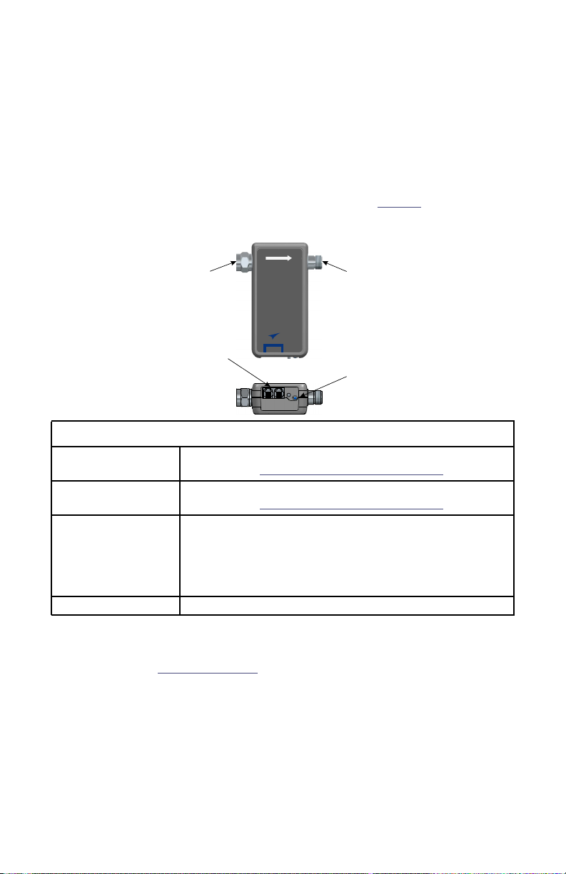
Figure 2 Bird 4043, RS-485 Serial Communication Power Sensor
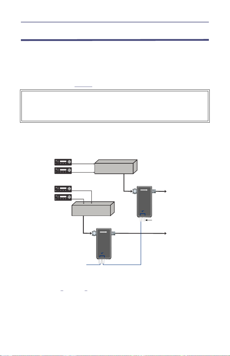
Each sensor is equipped with two RJ-25 jacks, either jack may be connected to a
CPM. The second RJ-25 jack may be used to extend the RS-485 bus to another
digital sensor. See
Figure 3 on page 3
. Multiple digital sensors may be serially
connected in this fashion, allowing as many as 16 sensors to be connected to a
CPM.
If multiple 4043 sensors are to be connected serially, each one is assigned a
unique address via the CPM. When each 4043 is connected to the CPM, prior to
connecting any additional 4043 sensors, they must be assigned an address by
the CPM, only then may an additional sensor be connected serially.
A termination plug must be used in the open RJ-25 jack on the rear panel of the
CPM or the open RJ-25 jack of the final digital sensor in the chain.
Features
RF Input N-Type (male) connector (shown), other connector types
available, see
"Model Identification" on page 12
RF Output N-Type (female) connector (shown), other connector types
available, see
"Model Identification" on page 12
Data Connectors
RJ-25 connector provides power and data connection. Only
one connector is required, second connector may be used to
extend RS-485 bus to additional digital sensors.
RJ-25 termination plug must be installed in unused jack or in
the Open port on the CPM.
Status LED Solid green: Power applied.

Directional Power Sensor 4043
3
Serial Communication Power Sensor Installation
The Bird 4043 Series Directional Power Sensors are designed to be used for
continuous power monitoring of Land Mobile Radio (LMR) systems. The 4043
can provide real-time RF forward and reflected power and VSWR
measurements.
This procedure is an example of one possible cable configuration, based on the
connection diagram in
Figure 3
.
1. Disable RF power for transmission lines to be disconnected.
2. Connect combiner's RF output cable to the 4043 RF input.
Figure 3 CPM, RS-485 Serial Connection Diagram
3. Connect 4043's RF output connector to the antenna cable.
4. Repeat step
1
through
3
for any additional 4043 power sensors.
5. Install RJ-25 termination plug in unused digital sensor RJ-25 port on the rear
panel of the CPM (if available), or in the last sensor installed in the digital
sensor chain.
6. Connect a data/power cable from the CPM to 4043 power sensor.
WARNING
Leaking RF energy is a potential health hazard. Never attempt to connect or
disconnect equipment from the transmission line while RF power is being
applied. Severe burns, electrical shock, or death can occur.

Serial Communication Model
4
Note: Each digital sensor must have a unique RS-485 Bus address
when connected serially to the CPM. Connect the digital sensors
one at a time, enroll the sensor using the CPM front panel to
provide a unique address, prior to connecting additional sensors.
7. Configure the sensor via CPM front panel. Refer to the CPM Operation
Manual.
8. If additional 4043 power sensors will be connected, connect a data/power
cable to the open RJ-25 jack, connect remaining end of cable to additional
4043 sensor.
9. Repeat step
7
and
8
for any additional 4043 power sensors serially
connected to the CPM.
Note: Digital sensors require a terminator plug be installed in the
open Digital Sensor RJ-25 port on the rear panel of the CPM (if
available), or in the last sensor installed in the digital sensor chain.
10. If required, install RJ-25 termination plug in unused RJ-25 Jack of last digital
sensor in the chain.

5
Chapter 3 Bluetooth Communication
Model
The 4043 Sensors with Bluetooth communications interface are designed to
connect to the Bird RF Meter App. Once connected, measurement data is
transfered to the RF Meter App, the RF Meter App will display the current
sensor measurements in numerical and graphical displays. For the sensor to
function it must have batteries installed or an external power source connected.
See
Figure 4
.
Figure 4 Bird 4043, Bluetooth Communication Power Sensor
Features
RF Input N-Type (male) connector (shown), other connector types
available, see
"Model Identification" on page 12
.
RF Output N-Type (female) connector (shown), other connector types
available, see
"Model Identification" on page 12
.
Battery
Compartment
Batteries are the primary source of power for the Bluetooth
model 4043 power sensor.
Three AAA batteries are required.
Auxiliary Power
Connectors
RJ-25 connectors are provided for an auxiliary power supply
source. A cable may be fabricated to supply 12 VDC instead
of using batteries. See
"External Power Supply Cable
Assembly" on page 8
.
Pair Button Places sensor in Bluetooth pairing mode for 1 minute after
button is pressed.
Status LED
Solid green: Power applied.
Flashing blue: Ready to pair over Bluetooth.
Solid blue: Paired to Bluetooth device.
Solid purple: Firmware update mode.
!
"
# !#" $
!%" %
& " &
'(
")'"$
!
! !&

Bluetooth Communication Model
6
The following power sources provide the required power to the Bluetooth 4043
sensor:
Internal Batteries (customer supplied) - Power may be supplied by
three AAA batteries. See
"Bluetooth Power Sources" on page 8
.
DC power supply (12 VDC nominal (7-18 VDC), minimum 50 mA) to
RJ25 - Power may be supplied from an external DC power supply
through the RJ-25 jack. See
"Bluetooth Power Sources" on page 8
.
Note: This device complies with part 15 of the FCC rules.
Operation is subject to the following two conditions. (1) This device
may not cause harmful interference. (2) This device must accept
any interference received, including interference that may cause
undesired operation.

Directional Power Sensor 4043
7
Bluetooth Communication Model Installation
A connection may be established to a 4043 Sensor using the Bird RF Meter App.
See
"Bluetooth Communication Model" on page 5
for additional information about
the Bluetooth operation.
1. If not previously connected to the RF Source, perform steps
a
thorough
c
.
a. Disable RF power for transmission lines to be disconnected.
b. Connect RF output cable to the 4043 RF input.
c. Connect 4043's RF output connector to the antenna cable.
2. Connect the 4043 sensor to a DC power source (Internal batteries, or a
suitable power supply. See
"Bluetooth Power Sources" on page 8
).
3. Press the pair button on the 4043 sensor.
Note: Perform the following steps within one minute.
4. Open the Bird RF Meter App.
5. Tap the menu icon at the top right of the screen.
6. Tap Network Scan.
The 4043 sensor will appear under the Found Devices heading.
7. Tap the 4043 sensor listed under Found Devices.
The App should connect to the device and display the sensor current
measurement readings.
Note: Use the RF Meter App’s Help content for instructions on
how to configure the App and sensor.
Pairing the 4043 Bluetooth Sensor with the Bird RF Meter App
First time pairing of a 4043 Sensor and a device running the Bird RF Meter App is
accomplished by pressing the Pair button on the 4043 Sensor, then initiating the
Bluetooth connection from within the RF Meter App.
Note: It is NOT necessary to pair with the 4043 Sensor through
the devices operating system.
After a device running the Bird RF Meter App has been paired with a 4043
Sensor it will no longer be necessary to press the pair button on the sensor for
future connections. The 4043 Sensor “remembers” the device to allow faster
connections via Bluetooth.
WARNING
Leaking RF energy is a potential health hazard. Never attempt to connect or
disconnect equipment from the transmission line while RF power is being
applied. Severe burns, electrical shock, or death can occur.

Bluetooth Communication Model
8
Bluetooth Power Sources
Internal Battery Operation
Note: Internal batteries are not required if an external power
cable assembly is supplying power to the 4043 Bluetooth Sensor.
1. Open the battery compartment on the 4043 sensor.
CAUTION
2. Insert three AAA size alkaline batteries. Verify the orientation of the
positive and negative terminals.
3. Close the battery compartment.
4. Follow the steps in
"Maintenance" on page 9
.
External Power Supply Cable Assembly
Note: This assembly is not required if internal batteries are
supplying power to the 4043 Bluetooth Sensor.
1. Using suitable wire, connect the power supply to an RJ-25 plug.
a. Connect the positive 12 VDC (7-18 VDC) supply output wire to
pin 1 of the RJ-25 plug and the ground wire to pin 2 (see
Figure 5
).
2. Insert the RJ-25 plug into either RJ-25 connector on the 4043 sensor.
3. Follow the steps in
"Maintenance" on page 9
.
Figure 5 RJ-25 Power Supply Connection
Be sure batteries are inserted in the proper orientation for correct polarity.
Improperly inserting batteries may cause damage to the sensor.

9
Chapter 4 Maintenance
There is no user maintenance for the 4043 power sensor, except battery
replacement in the Bluetooth model, See
"Bluetooth Power Sources" on page 8
for
battery replacement.
Contact the Bird Service Center in the event the power sensor requires
maintenance.
Customer Service
Any maintenance or service procedure beyond the scope of those in this
chapter should be referred to a qualified service center.
If the unit needs to be returned for any reason, request an Return Material
Authorization (RMA) through the Bird Technologies website. All instruments
returned must be shipped prepaid and to the attention of the RMA number.
Bird Service Center
30303 Aurora Road
Cleveland (Solon), Ohio 44139-2794
Fax: (440) 248-5426
E-mail: bsc@birdrf.com
For the location of the Sales Office nearest you, visit our Web site at:
http://www.birdrf.com

10
Chapter 5 Specifications
Specification Value
Frequency Range (model dependent)
144 to 940 MHz
See
"Model Identification" on page 12
for
frequency range of each model.
Forward Power Measurement Range 25 W to 500 W
Reflected Power Measurement Range 2.5 W to 50 W
RF Connectors
Input
Output
Type-N (male), Type 4.3-10 (male)
Type-N (female), Type 4.3-10 (female)
Impedance 50 ohms nominal
Insertion Loss (Max.) 0.2 dB
Insertion VSWR (Max.) 1.15
Peak/Average Ratio (Max.) 12 dB
Directivity 25 dB minimum
Measurement Accuracy ± 5% of reading
Data Interfaces (Model Dependent)
See
"Model Identification" on page 12
RS-485 Serial Interface,
Bluetooth1
RS-485 Data Interface Connector RJ-25
Power Supply Requirements
DC-RJ-25 Jack (CPM or External P.S.)
Battery Operation
7-18 VDC, < 50 mA
3 - AAA size alkaline batteries
Operating Temperature Range 0° C to +50° C (32° F to 122° F)
Storage Temperature Range -40° C to +80° C (-40° F to 176° F)
Humidity 95% maximum (non-condensing)
Altitude (Max.) 15,000 ft. (4572 m)
Weight (Approx.) 0.5 lb. (0.27 kg)
Dimensions, Nominal
Without Connectors
5.2 L x 3.8" W x 1.4" H
(132.0 mm x 96.5 mm x 35.5 mm)
Operating Position Any
Certifications
FCC
FCC part 15 modular certification
BMD-300/BMD-301 FCC ID: 2AA9B04
BMD-350 FCC ID: 2AA9B05

Directional Power Sensor 4043
11
IC
Industry Canada RSS-210 modular
certification
BMD-300/BMD-301 IC: 12208A-04
BMD-350 IC: 12208A-05
CE
EN 60950-1: 2011-01 3.1 (a): Health and
Safety of the User
EN 301 489-1 V1.9.2 & 3.1 (b):
Electromagnetic Compatibility
EN 301 489-17 V2.2.1
EN 300 328 V1.9.1 3.2: Effective use of
spectrum allocated
Japan (MIC)
Ministry of Internal Affairs and
Communications (MIC) of Japan pursuant to
the Radio Act of Japan
BMD-300: 210-106799 BMD-301: 210-
107153 BMD-350: 210-108944
Australia/New Zealand
AS/NZS 4268 :2012+AMDT 1:2013, Radio
equipment and systems - Short range
devices
Bluetooth BMD-300/301 RF-PHY Component (Tested) -
DID: D030629; QDID: 81876
1 This device complies with part 15 of the FCC rules. Operation is subject to the following
two conditions. (1) This device may not cause harmful interference. (2) This device
must accept any interference received, including interference that may cause
undesired operation.

Specifications
12
Model Identification
!
"
#
!!# "#
""# "#$%
$"$# $%
&'
( (
)**+ +,
) ,
- .
/"+01)&2
#3
4.
5.67*
5.6*
89++:4567*
89++:456*

Directional Power Sensor 4043
13
Table of contents
Other BIRD Accessories manuals
Popular Accessories manuals by other brands

Life
Life OBL-100 user manual

Celsius
Celsius CELMFT200 operating instructions

Lucky Reptile
Lucky Reptile Egg-o-Bator operating instructions

PCB Piezotronics
PCB Piezotronics ICP 483C30 Installation and operating manual

TP-Link
TP-Link HS100 user manual

Becker
Becker CentronicPLUS SC811 PLUS Assembly and operating instructions