BIRO 1433 Service manual

266-7-07-7

TABLE OF CONTENTS
Page
NOTICE TO OWNERS AND OPERATORS ......................................... 1
SAFETY TIPS ............................................................... 2
INSTALLATION ............................................................ 3-6
OPERATION ................................................................ 7
TO PROCESS PRODUCT ............................................... 7-8
CLEANING PROCEDURE ...................................................... 9
MAINTENANCE .............................................................10
GENERAL ............................................................10
LUBRICATION ......................................................11-12
WALL CHART (PART No. 671) ..................................................12
PARTS DIAGRAMS ........................................................13-20
SWITCH ASSEMBLIES AND SERVICE PARTS ......................................21
WIRING DIAGRAMS........................................................22-24
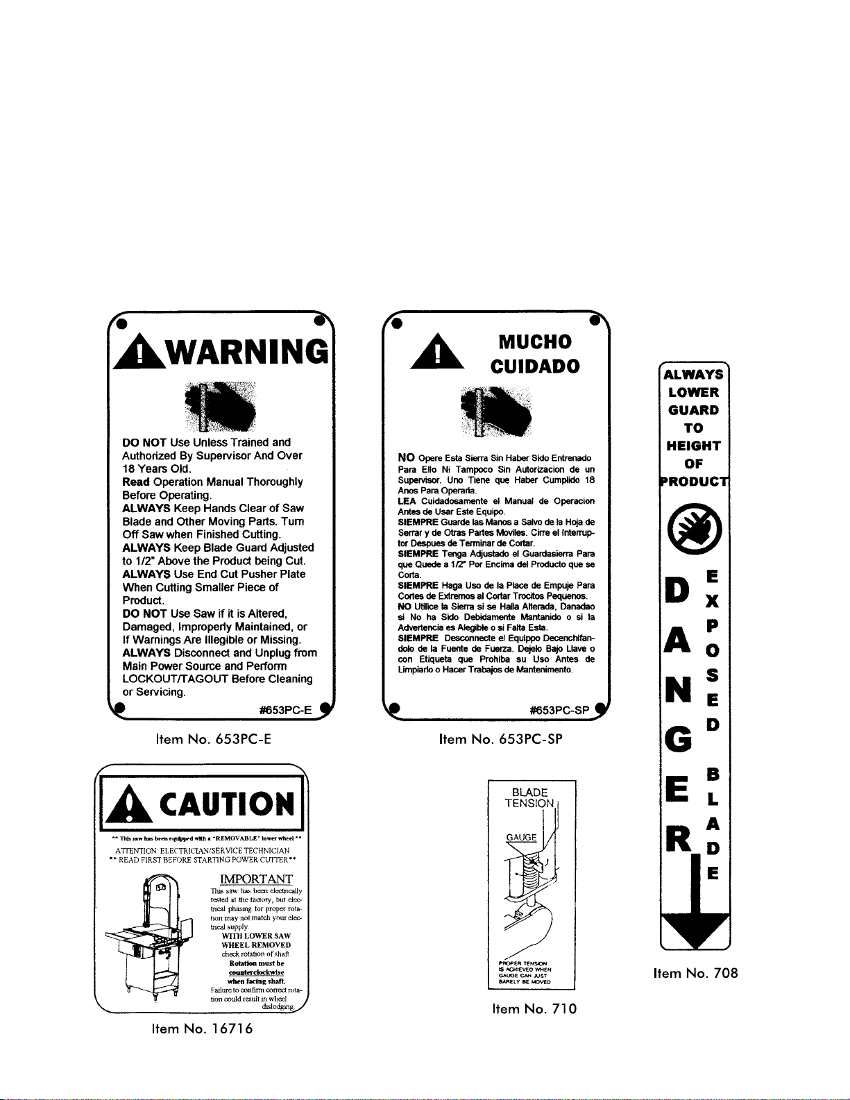
WARNING LABEL LOCATIONS ON MACHINE ......................................25
WEARABLE SAW PARTS ......................................................26
PARTS LIST/ORDERING.......................................................27
PARTS ASSEMBLIES LIST/ORDERING ...........................................28
OPERATOR’S SIGNATURE PAGE................................................29
LIMITED WARRANTY .........................................................30
NOTICE TO OWNERS AND OPERATORS......................................................................1
SAFETY TIPS........................................................................................................................2
INSTALLATION...............................................................................................................3-6
OPERATION........................................................................................................................7
TO PROCESS PRODUCT.........................................................................................8
CLEANING PROCEDURE.................................................................................................9
MAINTENANCE...............................................................................................................10
GENERAL................................................................................................................10
LUBRICATION..................................................................................................11-12
WALL CHART (PART NO. 671).......................................................................................12
OPERATOR’S NOTES.......................................................................................................13
PARTS DIAGRAM........................................................................................................14-22
OPERATOR’S NOTES.......................................................................................................16
SWITCH ASSEMBLIES AND SERVICE PARTS..............................................................23
WIRING DIAGRAMS...................................................................................................24-28
WARNING LABEL LOCATIONS ON MACHINE..........................................................29
WEARABLE SAW PARTS..................................................................................................30
PARTS LIST/ORDERING..................................................................................................31
PARTS ASSEMBLIES LIST/ORDERING..........................................................................32
OPERATOR’S SIGNATURE PAGE...................................................................................33
LIMITED WARRANTY......................................................................................................34

BIRO’s products are designed to process food products safely and efficiently. Unless the oper-
ator is properly trained and supervised, there is the possibility of a serious injury. It is the responsi-
bility of the owner to assure that this machine is used properly and safely, strictly following the
instructions contained in this Manual and any requirements of local law.
No one should use or service this machine without proper training and supervision. All opera-
tors should be thoroughly familiar with the procedures contained in this Manual. Even so BIRO
cannot anticipate every circumstance or environment in which its products will be used. You, the
owner and operator, must remain alert to the hazards posed by the function of this equipment –
particularly the SHARP MOVING BAND TYPE SAW BLADE. No one under eighteen (18) years of
age should operate this equipment. If you are uncertain about a particular task, ask your supervi-
sor.
This Manual contains a number of safe practices in the SAFETY TIP section. Additional warn-
ings are placed throughout the Manual. Warnings related to your personal safety are indicated by:
Warnings related to possible damage are indicated by:
BIRO also has provided a wall chart to be posted near the equipment. If any warning label, wall
chart, or Manual becomes misplaced, damaged, or illegible, please contact your nearest Distribu-
tor or BIRO directly for a replacement.
Remember, however, this Manual or the warning labels do not replace the need to be alert and
to use your common sense when using this equipment.
1
NOTICE TO OWNERS AND OPERATORS
OR
- NOTE -
A copy of this manual is included with each Model 1433 saw.
The descriptions and illustrations contained in this manual are not binding.
The manufacturer reserves the right to introduce any modification without
updating the manual.


4. To assemble meat guage plate (Part No. A14275) to the machine; Loosen the lock knob (Part No. 272-10)
on the right side meat guage bracket. Remove the meat guage gear rack (Part No. 14272) and insert into the
meat gauge plate. Be sure to hold meat gauge arm so that the release handle is depressed. Re-install the gear
rack by first inserting the rectangle end into the left hand meat gauge bracket, then swing the right hollow
round end of the gear rack into the original lock position. Upon aligning the gear rack with the capscrew
(Part No. 272-11), tighten the lock knob clockwise, fastening the locking cap screw into the hollow end to
the gear rack, CHECKING for a secure assembly. Keep gear rack well oiled with food grade oil to ensure
free movement.
SLIDE GIBS
HEAD
BASE
3

6.
7.
REMOVAL

7A.

14. Make sure saw guide bar with saw guard is in its lowest position. Close head and base doors.
15. Push start button and check for proper phasing of motor. Blade should be traveling down through saw guide.
16. Watch for proper tracking of blade. Back of blade should be centered in hole in saw guide in stationary bar (Part
No. 119A). Push stop button to stop machine.
17. Check placement of all warning labels, wall chart and Manual. Machine is ready for trained operators to process
product.
18. Contact your local Distributor or BIRO directly if you have any questions or problems with the installation or
operation of this machine.
WARNING LABELS AND WALL CHART
FOR BIRO POWER CUTTERS
SEE PAGE 11 AND 24 FOR LOCATIONS ON THIS MACHINE
6
SEE PAGE 12 AND 29 FOR LOCATIONS ON THIS MACHINE

7


CLEANING
SHARP MOVING BAND TYPE SAW BLADE
TO AVOID SERIOUS PERSONAL INJURY
ALWAYS Turn Off, Unplug From Power Source and Perform Lockout/Tagout Procedure to This
Machine BEFORE Cleaning or Servicing.
ONLY Use Recommended Cleaning Equipment, Materials and Procedures.
NEVER Spray Water or Other Liquid Substances Directly at Motor, Power Switch or any Other
Electrical Components.
ALWAYS Thoroughly Clean Equipment at Least Daily.
CLEANING THE BIRO POWER CUTTER:
Disconnect electrical power to the machine before cleaning. Parts to be removed have been made accessible and can
be removed without tools. Notice in the drawing below that all parts are numbered. Each part should be removed for
cleaning in the numbered sequence shown. To ensure cleaner cuts, keep the parts on the cleaning system in good
condition. Parts on the cleaning system which should be checked weekly, and changed as required are as follows:
Wheel Cleaners (Part No. 179), Saw Cleaners (Part No. 131), Saw Guide in Stationary Bar (Part No. 119A), Upper Saw
Guide (Part No. 602B), Lower Blade Back-Up Guide (Part No. S608) and Nylon Filler (Part No. 177).
9

SAW GUIDE BAR:

e. STATIONARY BAR ASSEMBLY: Check condition of nylon filler (Part No. 177), change every four (4) weeks.
Check condition of saw guide (Part No. 119A), check tracking of blade through guide, back of blade should
be centered in hole, replace every six (6) months. Check condition of lower blade back-up guide (Part No.
S608). Check adjustment of back-up guide, should have 132
²gap between back of blade and saw guide
carbide. Replace every six (6) months.
f. SAW CLEANERS: Check condition of blade cleaners, replace every four (4) weeks.
g. RATCHET ASSEMBLY: Check for smooth operation through full range of travel. Check condition of trigger
spring, replace as necessary.
h. SLIDE GIBS: Check that head structure moves freely up and down. Check for side to side and front to rear
tolerance. Adjust as required. Grease every four (4) weeks.
i. MEAT GAUGE ASSEMBLY: Check free movement of meat gauge plate on gear rack. Gear rack to be kept
lubricated at all times with light food grade oil. Check operation of release handle. Check that worm gear
engages properly with gear rack. Check tension of release handle spring, replace as necessary.
j. MEAT CARRIAGE ASSEMBLY: Check for free movement through full range of travel. Check for side to
side tolerance, adjust as necessary. Check condition and grease bearings, replace as necessary. Check
condition of thumb guard, replace as necessary.
k. SAFETY ITEMS: Safety end cut pusher plate is with machine and accessible. All warning labels are present,
properly affixed and legible. Model and Serial Number plate properly affixed and legible. Wall poster within
operator’s view from machine. Manual accessible to operator.
B. LUBRICATION
1. UPPER WHEEL BEARINGS: Grease every
four (4) months. Change grease every
twelve (12) months.
2. LOWER BEARING HOUSING: Grease
every four (4) months. Change grease every
twelve (12) months.
3. SLIDE GIBS: Grease every four (4) weeks.
4. MEAT CARRIAGE BEARINGS: Grease
every four (4) weeks.
5. SAW GUIDE BAR: Oil daily with food
machine oil.
6. MEAT GAUGE GEAR RACK: Oil daily
with food machine oil.
11
1. Remove the finger lift fastener knob and the fingerlift assembly.
2. Remove the finger lift fastener stud.
3. Push the saw guide bar up and out of the top of the head structure.
4. Remove the saw guide bar spring.
5. Clean and lubricate the babbitt pocket area (the square indented area
that seats the saw guide bar spring).
6. Lower the new saw guide bar spring through the top of the babbitt
pocket area and guide the spring into position with a standard
screwdriver. (NOTE: Drawing)
7. While holding the saw guide bar spring in position, re-enter the saw
guide bar from the top compressing the saw guide bar spring slightly
until the saw guide bar slides past the spring.
8. Replace the finger lift fastener stud, the finger lift assembly and the fin-
ger lift fastener knob.
9. Test by making several adjustments.
When lubricating the upper wheel bearing it is important that the three hex
head screws securing the upper wheel hub cap be loosened slightly before at-
tempting to pump grease into the grease fitting. Loosening the screws allows
for an escape of old broken down grease and air from the bearing cavity. Failure
to loosen the screws before greasing the upper bearings can cause the upper
shaft seal to be dislodged from the upper wheel allowing grease to escape and
moisture to get into the cavity. When finished greasing the bearings, retighten
the three screws. Take care to also clean off any grease that was forced out of
the cavity during greasing.

7. MOTOR BEARINGS: Bearing grease will lose its lubricating ability over time, not suddenly. The lubricating
ability of a grease (over time) depends primarily on the type of grease, the size of the bearing, the speed at which
the bearing operates and the severity of the operating conditions. Good results can be obtained if the following
recommendations are used in your maintenance program.
A high grade ball ro roller bearing grease should be used. Recommended grease for standard service conditions
is Polyrex EM (Exxon Mobil).
Equivalent and compatible greases include: Texaco Polystar, Rykon Premium #2, Pennzoil Pen 2 Lube, and
Chevron SRI.
Recommended lubrications intervals is every 9 months with the equivalent of two (2) teaspoons of grease.
PART NUMBER 671
WALL CHART “BAND SAW SAFETY GUIDELINES”
ATTACH TO WALL IN VICINITY OF MACHINE IN EASY VIEW OF OPERATOR
12
1. Before Using, Make Sure:
+Gauge Plate !And Other Components
Are Secure.
+All Warning Labels and Guards Are In Place.
+The Guide Bar "Is Adjusted To 12Inch
Above The Product To Be Cut.
2. While Cutting:
+Keep Hands and Fingers Away From Blade.
+Keep Product Securely Against Guage Plate.
+Use End Cut Pusher #When Making
Final Cuts. Item No. 256P.
3. Before Cleaning:
+Turn Off Power And Unplug.
+Remove Saw Blade.
+Use Extra Care When Handling The Saw Blade.

- NOTES -
13

14

15

- NOTES -
16

AS14005C
STAINLESS STEEL
HEAD & DOOR ASSEMBLY
15
Item No. Description
A16112 Head door latch assembly
AS14005C Head & door assembly, SS
AS14006 Head door assembly, SS
A71-1 Upper wheel hinge bracket assembly
HHS050S Hex head screw, 516-18 ´58SS
LW15S Lock washer, 516 SS
S14005C Head SS
S14006 Head door SS
Item No. Description
SSS15 Set screw, 516-18 ´516 cup point
14TH Head door hinge welded
14TP Head door hinge pin, 1½"
14TP-1 Head door hinge pin, 114"
14R Head door hinge – welded
112-212 Waved washer
16112 Head door latch
71-1 Upper wheel hinge bracket
17

16
Item No. Description
A14003U335-6 Upper wheel assembly w/hinge plate
A14003UDF335-6 Upper wheel assembly – double flange with
hinge plate
A14003U-6 Upper wheel assembly w/o hinge plate
A14003UDF-6 Upper wheel assembly – double flange without
hinge plate
A12335X Upper wheel hinge plate assembly
Item No. Description
A227 Upper bearing cup/cone assembly
A247 Upper shaft bearing assembly
A295 Wheel cleaner assembly
HHS005S Hex head screw, 8-32 ´½SS
HHS010S Hex head screw, 10-32 ´38SS
HN05S Hex nut, 8-32 SS
HN35S Hex nut, 38-16 SS
S12335X Upper wheel hinge plate
S229 Wheel cleaner arm spring, SS
S244 Wheel cleaner arm stud, SS
S253 Upper wheel aligning screw, SS
S295 Wheel cleaner arm, SS
S325 Wheel cleaner arm stud washer, SS
14003U-6 Upper wheel, 14”, 6 spoke
14003UDF-6 Upper wheel 14”, double flange
179 Wheel cleaner
230DL Upper shaft seal, double lip
234 Grease fitting
237 Upper shaft castellated lock nut
238 Upper shaft castellated lock washer
247 Upper shaft
248 Upper wheel hub cap
252X Upper shaft nut
513 Upper wheel hub gasket
530 Retaining ring (2 req.)
Item No. Description
A16547 Lower bearing housing assembly w/o wheel
A363 Lower bearing cup/cone assembly
HN35S Hex nut, 38-16, SS
LW20S Lock washer, 38,SS
SSS05S Set screw cup, SS, 10-24 ´38
14544 Grease seal, 1.50 ID
14545 Retaining ring, internal, 2716 ID
14548 Grease seal, 78ID
14549 Lower bearing housing cap
14550 Adjustment screw, lower bearing housing
14551 Hex jam nut, 58-11, SS
Item No. Description
14560 Lower saw wheel, 14”
14560DF Lower saw wheel 14”, double flange
14740 Retaining ring – external
14746 T-handle lock, removable lower wheel
16251-90X78AL Pulley, upper V-belt 9.0 ´78,AL
16517 Inner race spacer, removable wheel
16543 Shaft, lower saw wheel
16547 Lower bearing housing, removable wheel
280 Key
360A1 Grease fitting angular
360B-1 Set screw ½-13
18
Other manuals for 1433
1
Other BIRO Cutter manuals