BIS Scale House AFW Series User manual

2
LANGUAGES
SPRACHEN
LANGUES
LINGUE
ENGLISH ................................................................................................................3
DEUTSCH.............................................................................................................21
FRANÇAIS............................................................................................................39
ITALIANO..............................................................................................................57
BIS S.r.l.
Via Trieste, 31
20080 Bubbiano MI – Italia
Tel.: +39 02 90834207
Fax: +39 02 90870542
e-mail: [email protected]
P.IVA e C.F.: 03774900967
www.BilanceOnLine.it

3
ENGLISH
INDEX
1. INTRODUCTION................................................................................................................................................................4
2. MAIN TECHNICAL SPECIFICATIONS..............................................................................................................................4
3. INSTALLATION .................................................................................................................................................................5
3.1 CELL CONNECTION ................................................................................................................................................5
3.2 POWER SUPPLY AND START-UP ...........................................................................................................................5
3.3 BATTERY POWERED ..............................................................................................................................................6
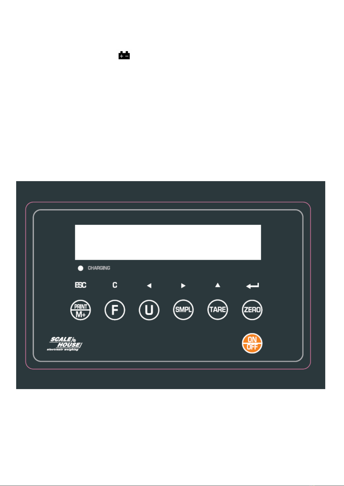
4. FRONT PANEL KEYS AND INDICATORS .......................................................................................................................6
4.1 FUNCTION OF THE KEYS.......................................................................................................................................7
4.2 FUNCTION OF THE INDICATORS...........................................................................................................................7
5. SYMBOLS ON LCD DISPLAY...........................................................................................................................................8
6. OPERATION......................................................................................................................................................................9
6.1 AUTOMATIC ZERO UPON START-UP.....................................................................................................................9
6.2 SCALE ZERO ...........................................................................................................................................................9
6.3 TARE FUNCTION .....................................................................................................................................................9
6.4 OVERLOAD MESSAGE............................................................................................................................................9
6.5 TOTALISATION OF THE WEIGHT............................................................................................................................9
6.5.1 MANUAL OR AUTOMATIC TOTALISATION................................................................................................10
6.5.2 TOTALISATION IN DISCHARGE.................................................................................................................10
6.6 COUNTING PIECES...............................................................................................................................................10
6.7 CHECKING QUANTITIES BY WEIGHT..................................................................................................................10
6.7.1 SETTING THE WEIGHT THRESHOLDS.....................................................................................................10
6.7.2 ACOUSTIC ALARMS IN CORRESPONDENCE TO THE HI-OK-LO LIMITS .............................................. 11
6.7.3 VISUAL INDICATION OF THE WEIGHT CHECK........................................................................................ 11
6.8 UNIT OF MEASURE CONVERSION ...................................................................................................................... 11
7. SET-UP ENVIRONMENT.................................................................................................................................................11
7.1 SET-UP ENVIRONMENT BLOCK DIAGRAM .........................................................................................................12
7.2 “F0 H-L” – SETTING WEIGHT THRESHOLDS.......................................................................................................12
7.3 “F1 toL” – TOTAL CLEARING .................................................................................................................................13
7.4 “F2 Unt” –CONFIGURATION OF SECONDARY UNITS OF MEASURE................................................................13
7.5 “F3 oFF” – ENABLING DISPLAY BACKLIGHTING AND ACOUSTIC ALARM ........................................................13
7.6 “F4 Prt” – SETTING MANUAL OR AUTOMATIC TOTALISATION...........................................................................14
7.7 “F5 rSt”....................................................................................................................................................................14
7.8 “ProG” – SCALE CONFIGURATION .....................................................................................................................14
7.8.1 “P1 REF” – METRIC PARAMETERS...........................................................................................................14
7.8.2 “P2 CAL” – CONFIGURATION AND CALIBRATION ...................................................................................15
7.8.3 “P3 Pro” – VISUALISATION OF A/D CONVERTER POINTS & MANUFACTURER’S SETTINGS ..............16
7.8.4 “P4 CHK” – ENABLING FILTER AND ENABLING TOTALISATION IN UNLOADING..................................16
8. SERIAL OUTPUT.............................................................................................................................................................17
8.1 TRANSMISSION MODES .....................................................................................................................................17
8.2 PRINTER CONNECTION .......................................................................................................................................18
8.3 FORMAT OF THE SERIAL COMMANDS................................................................................................................18
9. ERROR MESSAGES .......................................................................................................................................................19
RECYCLING INSTRUCTION...............................................................................................................................................19
DECLARATION OF CONFORMITY ....................................................................................................................................20
WARRANTY ........................................................................................................................................................................20

4
1. INTRODUCTION
This manual was created to help you install and learn all about the functional possibilities of the AFW scales.
WARNINGS
The scales should be sited in a location that will not degrade the accuracy.
Avoid extremes of temperature. Do not place in direct sunlight or near air conditioning vents.
Avoid unsuitable tables. The tables or floor must be rigid and not vibrate. Do not place near vibrating machinery.
Avoid unstable power sources. Do not use near large users of electricity such as welding equipment or large motors.
Avoid high humidity that might cause condensation. Avoid direct contact with water. Do not spray or immerse the scales in
water.
Avoid air movement such as from fans or opening doors. Do not place near open windows.
Keep the scales clean.
Do not stack material on the scales when they are not in use.
2. MAIN TECHNICAL SPECIFICATIONS
Model
Plate
(dimensions in mm)
Capacity kg
Division g
Resolution g
AFWC30
350x450
30
10
0,05
AFWC60
350x450
60
20
0,1
AFWC150
350x450
150
50
0,25
AFWD60
420x520
60
20
0,1
AFWD150
420x520
150
50
0,25
AFWD300
420x520
300
100
0,5
Stabilisation Time
1 Seconds typical.
Operative Temperature:
0°C - 40°C / 32°F - 104°F.
Power supply:
with fitted 240 Vac mains power adapter or with fitted battery
Battery life:
up to 90 hours of continuous use.
Recharge time:
12 hours.
Parameter Setup:
Calibration fully digital and programmable from the keyboard.
Display :
LCD backlit with 6 digits 24 mm high.
Case:
ABS Plastic.
Load cell drive voltage:
Max 5V/150mA.
Range of input signal
0 mV/V - 3 mV/V.
Load cells:
up to 4 load cells with input resistance of 350 Ohm.
Programmable Zero range:
+/- 2, 4, 10, 20, 50, 100 % of max load capacity.
Programmable Auto zero at start-up:
+/- 0, 2, 5, 10, 20 % of max load capacity.

5
3. INSTALLATION
AFWC-AFWD
a) Unpack the product.
b) Remove the transport locking screw above the platform.
c) Fix the column to the platform with the fitted screws
d) Fix the indicator to the column.
e) Level the platform by adjusting the adjustable feet until the bubble is in the centre of the level. The stability of the
platform is very important.
All the corners MUST REST IN A UNIFORM WAY. Carefully check that all feet fully rest on the ground and that the
platform, loaded on the corner, is not unstable (if a corner is not resting on the ground its relative foot is easier to turn).
Be sure the load cell is correctly connected to the indicator or an error will occur and the instrument setup will not
be accessible.
If a calibration has never been made, the indicator tries to do this automatically at the start-up (see also chap.
CONFIGURATION AND CALIBRATION in this manual).
3.1 CELL CONNECTION
Connect the female connector of the cable coming from the weighing module to the male connector placed on the rear of
the weight indicator, ad esso dedicato.
CONNECTION SCHEME
LOAD CELL FEMALE CONNECTOR MEANING
EXC + 5 EXCITATION +
EXC - 4 EXCITATION -
SENS + 5 REFERENCE +
SENS - 4 REFERENCE -
SIG + 1 SIGNAL +
SIG - 2 SIGNAL -
3.2 POWER SUPPLY AND START-UP
The indicator can be powered with a fitted 240 Vac external power adapter or just with the fitted battery.
NOTE: it is advisable to completely recharge the battery (12 hours) with the first installation of the instrument.
TO POWER the instrument through the 240 Vac mains put the AC/DC power plug in the appropriate socket on the back of
the scale and the power adapter in the 240 Vac mains socket.
TO TURN ON/TURN OFF the instrument press the ON/OFF key.

6
3.3 BATTERY POWERED
The weighing indicator can be operated from the battery if desired.
When the battery needs charging the symbol on the weight display will turn on. The battery should be charged
when the symbol is on. The scale will still operate for about 10 minutes after which it will automatically switch off to protect
the battery.
To charge the battery simply plug into the mains power. The scale does not need to be turned on.
The battery should be charged for 12 hours for full capacity.
You can find the “Charging”LED at the left of display to indicate the status of battery charging. When the scale is
plugged into the mains power the internal battery will be charged. If the LED is green the battery has a full charge. If it is
Red the battery is nearly discharged and yellow indicates the battery is being charged.
As the battery is used it may fail to hold a full charge. If the battery life becomes unacceptable then contact your distributor
4. FRONT PANEL KEYS AND INDICATORS

7
4.1 FUNCTION OF THE KEYS
- Clears the displayed gross weight if it’s within the configured percentage (see section
7.8.1) of the total capacity.
- A secondary function of "Enter" key when setting parameters or other functions.
- If pressed for an instant it executes the semiautomatic tare;
- A secondary function of incrementing the active digit when setting a value for
parameters or other functions.
- If pressed for an instant it allows to execute the reference operation (see section 6.6)
and then execute the conversion from pieces to weight and vice versa.
- In the numeric or alphanumeric input, it selects the digit to be modified, from left to
right.
- It allows to convert in the configured secondary units of measure (see section 6.8).
- In the numeric or alphanumeric input, it selects the digit to be modified, from left to
right.
-It allows to enter the set-up environment (see section 7)
-In the numeric input phase, it quickly clears the present value.
- If pressed for an instant it adds the value to the accumulation memory if the
accumulation function is not automatic.
- Secondary function (ESC) is to return to normal operation when the scale is in a
parameter setting mode.
- Turn on/turn off the power.
4.2 FUNCTION OF THE INDICATORS
INDICATOR
FUNCTION
Charging
Indicates that the battery is going to recharge (see section 3.3).

8
5. SYMBOLS ON THE LCD DISPLAY
The LCD display has symbols which show the indicator’s functioning status; you will find the description for each symbol
below.
SYMBOL
FUNCTION
Indicates that the battery is low (see section 3.3)
Managed for the QUANTITY CHECK BY WEIGHT (see section 6.7).
Indicates that the weight is stable.
GROSS
Indicates that the displayed value is a gross weight.
NET
Indicates that the displayed weight is a net weight.
ZERO
Indicates that the weight detected on the weighing system is near zero.
TARE
Indicates that a tare is enabled.
AUTO
Indicates that the automatic totalisation function is enabled.
Σ
Indicates that the weight has been totalised.
g
Indicates the unit of measure in use (gram).
pcs
Indicates that the number of sampled pieces is being displayed (see section 6.6).
g / pcs
Indicates that the average piece weight is being displayed (see section 6.6).
%
Not managed.
t
Not managed
HOLD
Not used in this application.
kg
Indicates the unit of measure in use (kilogram).
lb
Indicates the unit of measure in use (pounds).
OZ
Indicates the unit of measure in use (ounces).

9
6. OPERATION
6.1 AUTOMATIC ZERO UPON START-UP
The indicator has an “auto zero at start-up” function: in other words it means that if at start-up a weight within the
configured percentage (see section 7.8.1) of the capacity is detected, it will be zeroed; if the weight is not within this
tolerance, the display shows “Err 4” and with a non approved instrument the present weight after a few instants, while
with an approved instrument “Err 4” is shown continuously (one has to remove the weight in excess and turn on again
the scale).
6.2 SCALE ZERO
If there are no objects on the scale and the display shows a weight different than 0, press the ZERO key to clear (the
“ZERO” symbol turns on). If the weight is greater than the programmed percentage (see section 7.8.1) in respect to
the capacity, the zeroing will have no effect.
The zero function may be disabled in the set-up environment; see section 7.8.1.
The scale has an automatic rezeroing function to account for minor drifting or accumulation of material on the platform
(see section 7.8.1). However you may need to press the ZERO/ENTER key to rezero the scale if small amounts of
weight are shown when the platform is empty.
6.3 TARE FUNCTION
Zero the scale by pressing the ZERO key if necessary. The zero symbol will be on.
Place a container on the platform, a value for its weight will be displayed.
Press the TARE key to tare the scale when the “stable” is light. The weight that was displayed is stored as the tare
value and that value is subtracted from the display, leaving zero on the display. The "NET" indicator will be on. As
product is added only the weight of the product will be shown. The scale could be tared a second time if another type
of product was to be added to the first one. Again only the weight that is added after taring will be displayed.
When the container is removed a negative value will be shown.
To remove the tare, unload the scale and press again TARE.
6.4 OVERLOAD MESSAGE
Please do not add item that is over the maximum capacity. When reading “—OL—“ and hear beeping sound,
remove the item on the platter to avoid damage to the load cell.
6.5 TOTALISATION OF THE WEIGHT
The scale can be set to accumulate manually the weight on the scale by pressing the PRINT/M+ key (see charter 7.7).
The weight displayed will be stored in memory and printed when the PRINT/M+ key is pressed and the weight is
stable.
The display will show "ACC 01" and then the total in memory for 2 seconds before returning to normal.
Remove the weight, allowing the scale to return to zero and put a second weight on. Press the PRINT/M+ key, the
display will show " ACC 02" and then the new total.
Continue until all weights have been added.
To view and print the totals in memory press PRINT/M+ key when current scale in zero status (Zero indicator on)
To clear the accumulated total weight, press the Fkey when show total values.
It’s possible to cancel the accumulated total also in the set-up environment (see section 7.3)

10
NOTE:
- The totalisation functions with a minimum weight of 20d.
- The maximum number of totalisations is 999 while the maximum total value which may be accumulated is
999999.
Once reached these limits, one should clear the total; by pressing PRINT/M+ the message “AdErr” will appear on
the display.
- The total values will be cleared when it’s turned off.
6.5.1 MANUAL OR AUTOMATIC TOTALIZATION
The operation of accumulation, normally done manually with key PRINT/M+, can be done automatically when the
weight is stable. In regards to the choice of the totalisation execution mode see section 7.7.
6.5.2 TOTALISATION IN UNLOADING
The accumulation operation, normally executed with a positive net weight can be executed with a negative net weight.
To enable the totalisation in unloading function see section 7.8.4.
PROCEDURE
1) Put the articles to be unloaded on the scale and wait for the weight to become stable.
2) Tare the weight with the TARE key.
3) Remove the weight which you want to unload and wait for the weight to become stable (one will see a negative
weight).
4) Press the PRINT/M+ key (manual totalisation): the LED display will show for an instant “totAL” along with an
acoustic signal; if a print format has been linked, a printout will be made.
5) Repeat the operations from point 2.
6.6 COUNTING PIECES
Through the reference function it’s possible to use the scale as a piece counter.
COUNTING PROCEDURE
The operations to be carried out are the following:
1) Place the empty container on the scale and press TARE to tare it.
2) Check that the zero is on the display and put the quantity of pieces chosen for the SAMPLE on the scale and
press SMPL.
3) The display suggests a REFERENCE QUANTITY. The possible options are: 10, 20, 50, 100, and 200.
4) Press TARE the number of times needed to reach the desired sample size.
5) Press SMPL; the display will indicate SAMPL and the indicator will calculate the Average Piece Weight (APW).
After a few instants the display will indicate the quantity selected put on the platform.
6) Add the rest of the items to count in the container and whose value will appear on the display.
7) Unload the scale; the APW will remain stored in memory for the next counting of similar pieces, without having to
repeat the REFERENCE operation.
8) By pressing the SMPL key one switches from the display of the number of pieces to the display of the average
piece weight and of the net weight.
9) To cancel or to carry out a new reference operation, press the Fkey and repeat the operations as describe in
point 2).
NOTE: The weight must be greater than 20 divisions to execute the reference.
6.7 CHECKING QUANTITIES BY WEIGHT
The scale is fitted with the quantity check function with 2 weight thresholds. An acoustic alarm and three reference
symbols on the display are enabled on the basis of the set thresholds and the weighing result.
6.7.1 SETTING OF THE WEIGHT THRESHOLDS
See section 7.2.

11
6.7.2 ACOUSTIC ALARM IN CORRESPONDENCE OF THE HI-OK-LO LIMITS
One can decide if the acoustic alarm should enable when the “OK” symbol is on or when the “HI” or “LO” symbols are
on. To choose the alarm enabling mode, see section 7.6.
6.7.3 VISUAL INDICATION OF THE WEIGHT CHECK
Put a weight on the plate of the scale.
The indication symbols will enable depending on which thresholds have been configured:
WITH BOTH THRESHOLDS CONFIGURED
-The HI symbol of the LCD display will turn on when the detected weight exceeds the UPPER WEIGHT
THRESHOLD.
-The OK symbol of the LCD display will turn on when the detected weight is between the LOWER WEIGHT
THRESHOLD and the UPPER WEIGHT THRESHOLD.
-The LO symbol of the LCD display will turn on when the detected weight is less than the LOWER WEIGHT
THRESHOLD.
WITH THE UPPER THRESHOLD CONFIGURED AND THE LOWER THRESHOLD = 0
-The OK symbol of the LCD display will turn on when the detected weight exceeds the UPPER WEIGHT
THRESHOLD.
-The LO symbol of the LCD display will turn on when the detected weight is less than the UPPER WEIGHT
THRESHOLD.
WITH THE UPPER THRESHOLD = 0 AND THE LOWER THRESHOLD CONFIGURED
-The HI symbol of the LCD display will turn on when the detected weight exceeds the LOWER WEIGHT
THRESHOLD.
-The OK symbol of the LCD display will turn on when the detected weight is less than the LOWER WEIGHT
THRESHOLD.
NOTES
-The weight check function is enabled when the limit values are entered. To disable the function one should set the
limit values at zero.
-The function is not valid when one enters a lower limit greater than the upper limit.
-The weight check is enabled with a weight greater than the minimum weight (20d).
6.8 UNIT OF MEASURE CONVERSION
By pressing various times the U key the conversion into the configured secondary units of measure takes place (see
section 7.4); the relative symbol will turn on in the display (see section 5).
NOTE:
- The function is not available if the counting function is enabled or if the number of decimals of the weight is less than
3.
- With APPROVED instrument the weight in secondary units is displayed for 5 seconds, after which the display goes
to the scale unit of measure.
7. SET-UP ENVIRONMENT
The scale has various parameters that can be configured in the SET-UP environment.
To enter in the SET-UP environment press the Fkey in the weighing phase.
- The display will show the first function, " F0 H-L ":
- Pressing the TARE will cycle through the other functions.
- Pressing ZERO will allow you to set the function. It may be necessary to either use TARE or set a value using the U
key and the SMPL key to move the active digit and then using the TARE key to increment a digit, followed by the ZERO
key to enter the value.
- Use the PRINT/M+key to leave a parameter unchanged or to escape set-up environment.

12
7.1 SET-UP ENVIRONMENT BLOCK DIAGRAM
F1 toL
SETUP
ENVIRONMENT
F2 Unt
F0 H-L
F4 oFF
F5 Prt
SET Hi
SET Lo
to CLr
dECi
inC
CAP
CAL
P Cont,
SEi rE, ASK,
P AUto, P Prt
XXX.XXX
XXX.XXX
0, 1, 2, 3, 4
1, 2, 5, 10, 20, 50
XX.XXX
SEt dA
0AUto
0rAnG
Azn 0 oFF, 0.5d, 1d, 2d, 4d
0, 2, 5, 10, 20
0, 2, 4, 10, 20, 50, 100
lb
OZ
g
lbOZ
F3 ti
SEt ti
CLoCK
bL
bEEP
CLK on, CLK oFF
EL AU, EL oFF,
bP 1, bP 2, bP 3
on, oFF
on, oFF
on, oFF
on, oFF
on, oFF
on, oFF
ProG Pin P1 rEF
P2 CAL
P3 Pro tr i
Count
XXX.XXX
XXXXXX
P4 CHK ModE 1, ModE 2, ModE 3, ModE 4
to P-C
to Prt
SPEEd
F6 rSt
rESEt
SEtGrA 9,XXXXX
7.2 “F0 H-L” – SETTING WEIGHT THRESHOLDS
Set Lo SETTING LOWER THRESHOLD
By pressing ZERO the display shows “000.000kg”, with the first digit blinking, and it’s therefore possible to set the
lower threshold:
-Use the F key to clear the value, the TARE key to increase the value of the digit, the Ukey to go on the previous
digit and the SMPL key to go on the following digit.
-Confirm with ZERO the entered value or press PRINT/M+ to exit without confirming.

13
Set Hi SETTING UPPER THRESHOLD
By pressing ZERO the display shows “000.000kg”, with the first digit blinking, and it’s therefore possible to configure
the upper threshold:
-Use the Fkey to clear the value, the TARE key to increase the value of the digit, the Ukey to go on the previous
digit and the SMPL key to go on the following digit.
-Confirm with ZERO the entered value or press PRINT/M+ to exit without confirming.
7.3 “F1 toL” – CLEARING TOTAL
toCLr CLEARING TOTAL
By pressing ZERO it’s possible to clear the accumulated total weight.
Confirm with ZERO or press PRINT/M+ to exit without confirming.
to P-C
Not used in this application.
to Prt
Not used in this application.
7.4 “F2 Unt” – CONFIGURATION OF SECONDARY UNITS OF MEASURE
By pressing ZERO it’s possible to choose the units of measure for the conversion function (see section 6.8), enabling
(on) or disabling (oFF) the suggested secondary units of measure:
1) The display proposes the first secondary unit of measure to be enabled or disabled.
2) Press TARE to change the options and confirm with ZERO,or press PRINT/M+ to exit without confirming and
pass to the following unit.
3) The display proposes the 2nd secondary unit to be enabled or disabled.
4) Proceed as described in point 2 up until the last proposed unit of measure.
7.5 “F3 oFF” – ENABLING DISPLAY BACKLIGHTING, AND ACOUSTIC ALARM
bL DISPLAY BACKLIGHTING
By pressing ZERO it’s possible to programme the functioning mode of the backlighting.
Press TARE to change the options:
EL oFF backlighting always off
EL on backlighting always on.
EL AU backlighting on only when the weight is greater than 20d or when a key is pressed. When a key is pressed,
if the weight is less than 20d, the backlighting remains active for 5 seconds.
Confirm with ZERO or press PRINT/M+ to exit without confirming.
bEEP ACOUSTIC ALARM
By pressing ZERO it’s possible to decide whether the acoustic alarm should enable when the “OK” symbol is on or
when the “HI” or “LO” symbols are on.
Press TARE to change the options:
bP 1 acoustic alarm disabled
bP 2 active acoustic signal with active “OK” symbol.
bP 3 active acoustic signal with active “HI” or “LO” symbol.
Confirm with ZERO or press PRINT/M+ to exit without confirming.

14
7.6 “F4 Prt” – SETTING TOTALISATION AND TRANSMISSION MODE
TOTALIZATION AND TRANSMISSION MODE
Press TARE to select one of the suggested values:
P AUto Automatically upon weight stability.
P Prt Manually through the PRINT/M+ key.
P Cont continuous transmission with P Cont. protocol
SEr rE continuous transmission with SEr rE. protocol
ASK Transmission at request thorugh serial commands (see section 8.3)
Confirm with ZERO or press PRINT/M+ to exit without confirming.
TRANSMISSION SPEED
Press the TARE key to select one of the possible speeds : 600, 1200, 2400 4800, 9600.
Confirm with ZERO or press PRINT/M+ to exit without confirming.
TRANSMISSION PROTOCOL (only for PCONT mode)
Press the TARE key to select one of the possible protocol: Cont 1, Cont 2, Cont 3.
See section 8 for details.
Confirm with ZERO or press PRINT/M+ to exit without confirming.
PRINTER FORMAT (only for PAUTO and PPRT)
Press the TARE key to select one of the possible printing format: Lab 0, Lab 1, Lab 2, Lab 3.
See section 8 for details.
Confirm with ZERO or press PRINT/M+ to exit without confirming.
PRINTER TYPE
Press the TARE key to select one of the possible values:
tP enables the printing with ASCII printer (for example TPR).
711 Not used in this application.
LP50 Not used in this application.
Confirm with ZERO or press PRINT/M+ to exit without confirming.
7.7 “F5 rSt”
For use of the manufacturer.
7.8 “ProG” – SCALE CONFIGURATION
By pressing ZERO it’s possible to access the scale configuration menu. One is asked to enter the password.
To enter the menu press the U,PRINT/M+, and TARE keys, one after the other:
The display shows the first parameter, “P1 REF”.
7.8.1 “P1 REF” – METRIC PARAMETERS (*)
(*) In case of approved instrument the parameter is read only.
AZn ZERO TRACKING
By pressing ZERO one sets the zero tracking, in other words, scale’s thermal drift compensation parameter;
the set value corresponds to the number of divisions which is cleared.
Press TARE to select one of the suggested divisions: oFF, 0.5d, 1d, 2d, 4d.
0Auto AUTOMATIC ZERO AT START-UP
By pressing ZERO one sets the weight percentage for the automatic acquisition of the gross zero at start-up. If
at the start-up a weight is detected that is within the programmes percentage of the total capacity, it will be
cleared; if the weight is not within this tolerance, the display, after a few instants, shows the current weight.
Press TARE to select one of the suggested percentages: +/- 0, 2, 5, 10, and 20 % of the max. capacity.
Confirm with ZERO or press PRINT/M+ to exit without confirming.

15
0rAnG MANUAL ZERO RANGE
By pressing ZERO one sets the weight percentage for the manually acquiring the gross zero; if, in the normal
weighing phase, by pressing ZERO, a weight within the programmed percentage of the total capacity, it will be
cleared.
Press TARE to select one of the suggested percentages: +/- 2, 4, 10, 20, 50, or 100 % of the max. capacity.
Confirm with ZERO or press PRINT/M+ to exit without confirming.
SPEED SETTING ADC CONVERTER READING SPEED
By pressing ZERO one sets the reading speed of the ADC converter; the set value corresponds to the number
of readings made in a second.
Press TARE to select one of the suggested reading speeds: 7.5, 15, 30, 60.
Confirm with ZERO or press PRINT/M+ to exit without confirming.
7.8.2 “P2 CAL” – CONFIGURATION AND CALIBRATION (*)
Premise: through this step it’s possible to configure and calibrate a single cell scale, or a scale having various
cells equalised externally through the junction box; the scale is connected on the only channel on the indicator.
The unit of measure of the calibration is fixed at kilogram (“kg”).
(*) In case of approved instrument the parameter is read only.
DECi NUMBER OF SCALE DECIMALS
By pressing ZERO one selects the number of scale decimals.
Press TARE to select one of the suggested values: 0.0 (a decimal),0.00 (two decimals), 0.000 (three
decimals), 0.0000 (four decimals), 0 (no decimal); confirm with ZERO.
Confirm with ZERO or press PRINT/M+ to exit without confirming.
inC MINIMUM SCALE DIVISION
By pressing ZERO one selects the minimum scale division.
Press TARE to select one of the suggested values: 1, 2, 5, 10, 20, and 50.
Confirm with ZERO or press PRINT/M+ to exit without confirming.
CAP SCALE CAPACITY
By pressing ZERO one selects the total capacity of the scale.
-Use the Fkey to clear the value, the TARE key to increase the digit value, the Ukey to go on the previous
digit and the SMPL key to go on the following digit.
-Confirm the entered value with ZERO or press PRINT/M+ to exit without confirming.
CAL SCALE CALIBRATION
-Press ZERO, the display shows “UNLOAD”;
-Unload the scale and press ZERO when the stability led is on;
-Set the sample weight value by using the Fkey to clear the value, the TARE key to increase the value of
the digit, the Ukey to go on the previous digit and the SMPL key to go on the following digit. Confirm the
entered value with ZERO, the display shows “LOAD”;
-Put the sample weight on the scale and press ZERO when the stability indicator is on;
-If the calibration is correct, the display shows “PASS” for an instant, and the indicator returns to weighing;
-If the calibration is wrong, the display shows “FAIL” for an instant and then “CAL”.

16
IN CASE THE ZONE OF USE IS DIFFERENT FROM THE CALIBRATION ZONE ONE SHOULD:
1) Enter in the SET-UP environment of the scale (press the Fkey in the weighing phase).
2) Enter in the ProG >> P3 Pro >> SEtGrA step and set the gravity acceleration value for the
CALIBRATION ZONE
3) Carry out the calibration as previously described.
4) Save and exit from the SET-UP environment (press many times the PRINT/M key).
5) Enter the SET-UP environment of the scale and enter the ProG >> P3 Pro >> SEtGrA step and set the
gravity acceleration value for the ZONE OF USER.
6) Save and exit the SET-UP environment (press many times the PRINT/M key).
7) The weight error caused by the error of a different gravitational attraction value between the calibration
zone and the zone of use is corrected automatically.
7.8.3 “P3 Pro” – VISUALISATION OF A/D CONVERTER POINTS AND MANUFACTURER’S
CONFIGURATION
(*) With approved instrument the parameter is read-only.
(*) tr i
For use of the manufacturer.
CoUnt A/D CONVERTER POINTS
By pressing ZERO the instrument shows the A/D converter points relative to the weight on the scale.
Press PRINT/M+ to exit the step.
(*) rESEt
For use of the manufacturer.
(*) SEtGrA GRAVITY ZONE AND ZONE OF USE
Through this step one selects the acceleration value of calibration and of use of the instrument:
Manual entry of the g value: one may manually enter the gravitational acceleration value; one must modify
the 6 decimal digits of the gravitational acceleration.
In case one enters a wrong g value: the minimum decimal value is suggested (9,75001); a wrong value is any
decimal number that is not between 9,75001 and 9,84999 (inclusive).
7.8.4 “P4 CHK” – ENABLING FILTER AND ENABLING TOTALISATION IN UNLOADING
By pressing ZERO one chooses whether to enable the filter intervention for the stability of the weight indication
or enable the totalisation in unloading function, useful for totalising with a negative net weight.
Press TARE to change the options:
ModE 1 Filer disabled and totalisation in unloading disabled.
ModE 2 Filter enabled and totalisation in unloading disabled.
ModE 3 Filter disabled and totalisation in unloading enabled.
ModE 4 Not used in this application.
Confirm with ZERO,or press PRINT/M+ to exit without confirming.

17
8. SERIAL OUTPUT
Specifications
RS-232 output for the transmission of the weight data
ASCII code
Baud 4800 (selectable from 600 - 9600)
data bits 8 –n –1
No Parity
Connector: 9 pin (female)
Pin 2: RECEPTION
Pin 3: TRANSMISSION
Pin 5: GND
8.1 TRANSMISSION MODES
The transmitted data format varies depending on the selected transmission mode (see step F4, section 7).
“PAUTO” AND “P PRT” MODE
Totalisation Mode
In the normal weighing operations when one is accumulating the weight the data format depends on the printer format
selected in the F4 step, see section 7:
LAB 0
LAB 1
LAB 2
LAB 3
NO. 1
G 400.0kg
NO. 1
N 200.0kg
T 200.0kg
G 400.0kg
NO. 1
G 400.0kg
Total 1000.0kg
NO. 1
N 200.0kg
T 200.0kg
G 400.0kg
Total 1000.0kg
When the totals are recalled from the storage (see section 6.6.3) the data format is the following:
“P CONT” MODE
In this transmission mode the instrument transmits continuously the data format depending on the protocol selected in the
F4 step, see section 7:
Cont 1 protocol
Normal mode
Counting mode
Cont 2 protocol
Not used in this application
Progressive of totalisations
ST,GSXXX.XXXXkg<CR><LF>
ST for stability, US for instability
GS for gross weight, NT for net weight
PCS:XXXXXXX pcs<CR><LF>
Number of pieces

18
Cont 3 protocol
Not used in this application
SEr rE MODE
In this transmission mode the instrument transmits continuously the following data format:
ASK MODE
In this transmission mode it’s possible to execute operations on the scale upon request through the serial commands (see
section 8.3)
8.2 PRINTER CONNECTION
TPR
STANDARD
CABLE
AFW (9 Pin connector)
GND
Black
GND
CTS
Yellow
-
RX
Grey
TRANSMISSION
TPR printer power supply
STANDARD
CABLE
POWER SUPPLY
+VP and +VC
Red and Orange
+V (5V / 5A)
GND and GND
Black and Black
- V
NOTES:
- Set the following parameters in the AFW (see section 7):
F4 >> TRANSMISSION MODE >> PAUTO or P PRT
F4 >> SPEED >> 9600
F4 >> PRINTER TYPE >> tP
8.3 FORMAT OF THE SERIAL COMMANDS
COMMAND
FUNCTION
R<CR><LF>
Reading of the weight with data format as described in the section 8.1 “Cont1” protocol.
T<CR><LF>
Automatic tare, tares the weight on the scale.
Z<CR><LF>
Clears the gross weight.
ST,GS,XXX.XXXX,kg<CR><LF>
ST for stability, US for instability
GS for gross weight, NT for net weight

19
9. ERROR MESSAGES
ERROR MESSAGES
DESCRIPTION
RESOLUTION
- - oL - -
Over range
Remove weight from the scale.
Err 4
Zero Setting Error
Upon start-up or when the ZERO key is pressed, the weight on the
scale exceeds the percentage programmed on the max. capacity.
Remove the excess weight and retry.
Err 6
A/D out of range
The values from the A/D converter are outside the normal range.
Remove weight if overloaded, make sure the load cell is attached.
Indicates the load cell or the electronics may be faulty.
If the problem persist contact your dealer
RECYCLING INSTRUCTION
The crossed-out wheeled bin on the product means that at the product end of life, it must be taken to
separate collection or to the reseller when a new equivalent type of equipment is purchased. The
adequate differentiated refuse collection in having the product recycled, helps to avoid possible
negative effects on the environment and health and supports the recycling of the materials of which
the equipment is made. The unlawful disposal of the product by the user will entail fines foreseen by
the current regulations.

20
DECLARATION OF CONFORMITY
This device conforms to the essential standards and norms relative to the
applicable European regulations. The Declaration of conformity is available in the
web site www.scalehouse.it.
WARRANTY
Scale House products are guaranteed for a period of twelve months from delivery,
excluding the parts classified as expendable materials such as mechanical printing
heads, batteries, electric motors and wheels. The warranty for these expendable
materials is three months. The warranty refers to breakdowns resulting from any
construction defect or material defect of the product supplied and covers the cost
of labor and spare parts. The product must be returned to the Seller address in its
original packaging with shipping paid by the sender. The warranty does not apply
to breakdowns due to improper use or non-observance of the operating
instructions, electrical phenomenon, unauthorized repair attempt, connection to
other equipment or removal of any product identification elements (serial number,
label, etc.). This warranty does not provide for any compensation for damages,
direct or indirect, incurred by the user due to complete or partial failure of
instruments, even during the warranty period. The warranty for the load cells
excludes the damages caused by knocks and overloads.
AUTHORISED SERVICE CENTRE STAMP
This manual suits for next models
8
Table of contents
Languages:
Popular Accessories manuals by other brands

Intenso
Intenso S10000-C user manual

DOMUS LINE
DOMUS LINE PIR4 installation instructions

Orbit baby
Orbit baby helix plus instruction manual

Euroflex
Euroflex MB-flex S Quick installation guide

Honeywell
Honeywell DT6360STC installation instructions

Cooper Lighting
Cooper Lighting HALO Home HIWMSB1BLE40AWH installation instructions